
TRANSFORMATION RULES FROM CONCEPTUAL MODEL TO
NAVIGATIONAL MODEL IN HYPERMEDIA APPLICATIONS
Didier Assossou, Maxime Wack
University of Technology of Belfort-Montbeliard , 90010 Belfort cedex, France
Keywords: Modeling, Design, Hypermedia applications, Conceptual model, Navigational model, Transformation rules,
Classes, Nodes, Relationships, Link, Index, Guided tour.
Abstract: During the hypermedia applications modeling and design process, the passage from conceptual model to
cooperative navigational model is a critical transition which needs consistency and precise rules to structure
the navigation from the application domain information. In this paper, we propose some transformation
rules from conceptual model to cooperative navigational model. We have elaborated a set of transformation
rules to transform classes into nodes and relationships into links. These rules allow generating a first level
navigational diagram from the hypermedia applications conceptual model.
1 INTRODUCTION
Hypermedia applications modeling and design is an
incremental process, which can be perform in six
steps: domain analysis, conceptual design,
navigational design, media composition, abstract
interface design and implementation. Each step is
linked to one model and includes one or many
diagrams. During this modeling process the passage
from conceptual model to navigational model is a
critical transition, which needs consistency and
precise rules. Indeed the designers can envisage
different navigational diagrams for the same
application. Therefore it’s suited to have a base
navigational diagram from which the designers can
derive all those navigational diagrams. This base
navigational diagram common to all the designers
can only be obtained from conceptual diagram by
establishing some precise derivation rules,
understandable by all the designers.
2 OVERVIEW OF OUR
APPROACH
To model hypermedia applications, we have
elaborated a method called HMDM (Hypermedia
Modeling and Design Method) (Assossou, 2005a).
It’s a user-centric method, which can be used to
model and design many hypermedia applications
including interactive and Internet/Intranet
applications. HMDM comprises six steps: domain
analysis, conceptual design, navigational design,
media composition, abstract interface design and
implementation.
The analysis step comprises the user model and
the interaction model. At the end of the step, use
case diagrams, sequence diagrams and collaboration
diagrams are generated. This first step allows
delimiting precisely the application domain. It
describes the different way to use the application in
accordance with the users’ point of view. The next
step is the conceptual design. It is characterized by
the construction of a multimedia classes diagram.
The goal of this step is to describe on the one hand
the structure and the characteristics of the objects,
which intervene in the application domain and on
the other hand the relationships between those
objects.
The third step consists of navigational design.
During this step the information represented in the
conceptual model is reorganized in order to structure
the users’ navigation in the application. The designer
works on navigational spaces, navigational elements
(nodes, links) and access structures. The result is a
set of nodes, links, spaces and access structures
classes (Assossou, 2002). For each node class, a list
of temporal and spatial media is built. At the end of
the step, different levels of cooperative navigational
diagrams are generated.
428
Assossou D. and Wack M. (2006).
TRANSFORMATION RULES FROM CONCEPTUAL MODEL TO NAVIGATIONAL MODEL IN HYPERMEDIA APPLICATIONS.
In Proceedings of WEBIST 2006 - Second International Conference on Web Information Systems and Technologies - Internet Technology / Web
Interface and Applications, pages 428-434
DOI: 10.5220/0001256304280434
Copyright
c
SciTePress

The fourth step is focused on media composition
(Assossou, 2005b). The application is broken up into
scenes and the nature (temporal or spatial) of
different media, which intervene in each scene, is
identified. Then these media are composed in time
and space at the scene level.
The fifth step deals with the application abstract
interface design. For this a high-level interface
element (window or web page) is associated with
each scene. For each media represented in the scene,
we indicate the interface object (panel, button…),
which can display it. Moreover the way these objects
will react to user’s actions is defined. The step is
built on a set of interactive cooperative objects
(ICO) (Palanque, 1995) classes and a set of abstract
interface diagrams. For each high-level interface
element will correspond an instance of ICO class.
This latter allows establishing a table (the activation
function) presenting the scene media, corresponding
interface objects, actions that users can do on the
objects and activated services. The step ends by the
design of the ICO abstract interface diagrams. The
implementation of the application is the last step of
HMDM method. The designer chooses a platform
where the different models will be implemented.
3 THE CONCEPTUAL MODEL
The conceptual model expresses the static aspect of
a hypermedia application. It’s described by a
multimedia classes diagram. It represents the
classes, which intervene in the application and the
relationships between those classes. A singleton MC
defines the conceptual model: MC = {DCM} where
DCM represents a multimedia classes diagram.
3.1 The Multimedia Classes Diagram
The multimedia classes diagram DCM is defined by
a set C of multimedia objects, a set R of
relationships between these classes and a set E
t
which designates the heading of the diagram.
DCM = {E
t
, C, R} where:
- E
t
= <number, name, date>
The number allows identifying the diagram.
The name indicates the title of the diagram.
The date is the date of the diagram design.
- C = <P, N, A, M>
P is a pictogram, which indicates the nature of C
class.
N is the name of the class.
A designates the set of multimedia attributes and
has this form: [a
1
: t
1
, a
2
: t
2
,…, a
n
: t
n
] where a
n
is
the name of the attributes and t
n
the type of the
attributes. This type is a multimedia type.
M designates the set of the class method.
- R = <R
c
, R
sg
, R
a
>
R
c
designates the class relationships.
R
sg
designates the specialization/generalization
relationships.
R
a
designates the aggregation relationships.
The multimedia classes diagram at figure 1
illustrates an e-commerce application, which
involves a wholesaler of computing equipment. We
use UML (Muller, 2000) notation with some
pictograms, which represent the multimedia types.
Figure 1: Example of multimedia classes diagram.
4 THE COOPERATIVE
NAVIGATIONAL MODEL
The cooperative navigational model allows
elaborating the navigational structures (nodes, links
and spaces). It’s composed from one part of a set of
transformation rules, which allow generating the
navigational elements from the conceptual model
and in other part of a set of cooperative navigational
diagrams. The cooperative navigational model is
defined by the set MNC = {R
T
, DNC} where:
- R
T
is a set of passage rules from conceptual
model to navigational model,
- DNC designates a set of cooperative
navigational diagrams.
4.1 The Node Access Primitives
The nodes access primitives are composed of the
links, the index, the guided tours and the index
guided tours.
Multimedia classes diagram
1
1..*
Put in an order
1..*
1
1
1..*
1..*
0..*
0..*
Contain
Appear
CodeOr
CodeSu
DateOrder
DateDeliver
Adressee
Street
Zip
City
Country
ModePay
ORDER
CodeCu
FNameCu
LNameCu
Street
Zip
City
Country
Email
Phone
Fax
Login
Password
CUSTOMER
CodeSu
FNameSu
LNameSu
Adress
Zip
City
Country
Email
Phone
Fax
Remak
SUPPLIER
CodeCatalog
CodeProduct
DateValid
CATALOGUE
CodePromo
CodeCatalog
BiginDate
EndDate
PromoPrice
Photo
PROMOTION
CodeCategory
LibCategory
CATEGORY
PRODUCT
CodeProduct
Designation
TypeProduct
Constructor
CodeSu
UnitPrice
CodeCategory
QteStock
Availability
Details
1
1
1
1
Belong
1
CodeOr
CodeProduct
Quantity
UnitPrice
CADDIE
Supply
Wholesaler
A
A
A
A
A
A
A
A
A
A
A
A
A
A
A
A
A
A
A
A
A
A
A
A
A
A
A
A
A
A
A
A
A
A
A
A
A
A
A
A
A
A
A
A
A
A
A
A
A
A
A
A
A
A A
A
A
A
A
A
A
A
A
A
TRANSFORMATION RULES FROM CONCEPTUAL MODEL TO NAVIGATIONAL MODEL IN HYPERMEDIA
APPLICATIONS
429

4.1.1 The Link
Among the links we distinguish the unidirectional
links, the bi-directional links and the inheritance
links. The two first one are used to navigate from a
source node to a target node (and to come back from
the target node to the source node). The inheritance
link allows joining a super class node to the nodes
corresponding to his sub-classes.
4.1.2 The Index
An index is like a summary and is composed of an
objects list. It provides a direct access to each
element of the list. An index can be unidirectional or
bi-directional.
Figure 2: An index.
4.1.3 The Guided Tour
A linear path through an objects collection
characterizes a guided tour. The user can move
forward or backward in the collection. There are
many types of guided tour. The circular guided tour
links the last element to the first one. The "home"
guided tour includes a main node, which can be
access from any other node. The guided tour with
entrance and exit (Isakowit, 1995) comprises
different entrance and exit nodes. A guided tour can
be unidirectional or bi-directional.
4.1.4 The Index-guided Tour
The index-guided tour is a combination of an index
and a guided tour. Like this two primitives, the
index-guided tour can be unidirectional or bi-
directional.
Figure 4: An index-guided tour.
Figure 5: Nodes access primitives representation.
4.2 Transformation Rules
To elaborate the cooperative navigational model
from conceptual model, we have established a set of
rules, which allow transforming classes into nodes
and relationships into links. We distinguish two
types of rules: rules related to classes transformation
and those, which deal with relationships
transformation.
4.2.1 Transformation of the Classes
The first rule concerns the transformation of the
classes of the multimedia classes diagram in
navigational elements.
R1(p) : One class generates one or many nodes
due to the tasks to accomplish.
Guided Tour
France
Italy
Spain
Greece
Country
Index
France
Italy
Spain
Greece
Country
Spain
Italy
Greece
France
Figure 3: A guided tou
r
.
Index-guided tour
France
Italy
Spain
Greece
Country
Spain
Italy
Greece
France
Unidirectional link
Bi-directional link
Unidirectional index
Unidirectional guided tour
Bi-directional guided tour
Inheritance link
Bi-directional index
Index-guided tour
undirectional
Index-guided tour
bi-directional
WEBIST 2006 - WEB INTERFACES AND APPLICATIONS
430

Generally the attributes of a node come from one
class (one can take all or a part of the attributes of
the class). Nevertheless, the attributes of a node can
come from many classes. In the same way, from one
class, one can create a lot of nodes.
4.2.2 Transformation of the Relationships
The transformation rules of the relationships take
into account the different types of relationships: one-
one, one-many, many-many, n-ary and inheritance
relationship.
One-one relationship
A one-one relationship is a binary relationship with
0..1 or 1 multiplicity at each side.
R2(p): A one-one relationship is transformed in
a unidirectional or bi-directional link.
Figure 6: One-one relationship transformation.
One-many relationship
A one-many relationship is a binary relationship
with * or 1..* at one side and 0..1 or 1 to the other
side.
R3(p): A one-many relationship is transformed
into a unidirectional index or in a unidirectional
guided tour or in a unidirectional index-guided tour.
Figure 7: One-many relationship transformation.
Many-many relationship
A many-many relationship is a binary relationship
with * or 1..* on each branch. A many-many
relationship can have some properties.
Many-many relationship without properties
R4(p): A many-many relationship without properties
is transformed into a bi-directional index or into a
bi-directional guided tour or in a bi-directional
index-guided tour.
Figure 8: Many-many relationship without properties
transformation.
Many-many relationship with properties
A many-many relationship with properties is
represented by a class-relationship in the conceptual
model. This class-association contains the
relationship properties. It’s connected to the
relationship link by a dotted line.
R5(p): A many-many relationship with properties
is transformed into a node with two unidirectional
links toward the nodes representing the classes
which have generated the relationship.
Figure 9: Many-many relationship with properties
transformation.
N-ary relationship
An n-ary relationship is a relationship which
connects n classes. An n-ary relationship can have
some properties. An n-ary relationship without
additional constraints is represented by:
A B
0..1
or
1
0..1
or
1
A
B
Unidirectional link
or
Bi-directional link
A
B
A B
0..1
or
1
*
or
1..*
Unidirectional index
Unidirectional index-guided
tour
A
B
A
B
A
B
or
Unidirectional guided tour
or
Bi-directional index
or
Bi-directional guided tour
A
B
A
B
Bi-directional
index-guided tour
A
B
A B
*
or
1..*
*
or
1..*
or
A B
*
or
1..*
*
or
1..*
A
C
C
B
TRANSFORMATION RULES FROM CONCEPTUAL MODEL TO NAVIGATIONAL MODEL IN HYPERMEDIA
APPLICATIONS
431

- a lozenge which connects the classes of the
relationship and a class-relationship,
- or a class with a stereotype which shows that the
class realizes the relationship.
R6(p): An n-ary relationship is transformed into a
node with n unidirectional links directed toward the
nodes representing the classes which have generated
the relationship.
Figure 10: N-ary relationship transformation.
Inheritance relationship
R7(p): An inheritance relationship is transformed
into an inheritance link.
Figure 11: Inheritance relationship transformation.
4.3 The Cooperative Navigational
Diagram
The cooperative navigational diagram (DNC) is a set
of spaces containing some nodes and some links.
The spaces are of three types (public, private and
appointment). By default a space is public and the
access to this space is totally free, while the access
to private and appointment space is controlled. The
nodes contain some anchors and are connected by
some links. A cooperative navigational diagram
(DNC) is composed of a set of sub-diagrams of
different level.
DNC = {(DNC) j}1≤j≤6 with (DNC)j = < E
t
, CN>
where
- E
t
= <number, name, date> is the heading of the
diagram.
The number allows identifying the diagram.
The name indicates the title of the diagram.
The date is the date of the diagram design.
- CN = {Space, Node, Link, Anchor, StructAcces,
Semaphore} designates the set of navigational
classes.
Space is the set of the spaces.
Node is the set of nodes.
Link is the set of links.
Anchor is the set of the anchors.
StructAcces is the set of the nodes access
structures.
Semaphore is the access to a private space.
There are different levels of cooperative
navigational diagram. The first level cooperative
navigational diagram is obtained by using the
transformation rules. In our example we have the
diagram at the figure 12. We have not mentioned the
attributes in order to not alter the diagram.
Figure 12: First level cooperative navigational diagram.
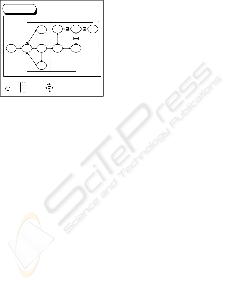
The second level cooperative navigational
diagram is obtained from the first level cooperative
navigational diagram on which we delimit the
private space, the public space and the appointment
space. The figure 13 represents the second level
cooperative navigational diagram of our example.
We can distinguish the nodes of public space and
private space. Notice that in our example we have
not an appointment space.
A
*
or
1..*
*
or
1..*
A
CA
B
C
CA
B
*
or
1..*
C
A
B
A
C
B
C
ORDER
CUSTOMER
PRODUCTCADDIE
CATALOGUEPROMOTION
SUPPLIERCATEGORY
Cooperative navigational diagram
Wholesaler
DNC1
WEBIST 2006 - WEB INTERFACES AND APPLICATIONS
432
5 RELATED WORK
The passage of conceptual model to navigational
model has been treated in different ways by the
different hypermedia design methods. RMM
(Isakowit, 1995) starts navigational step by
designing the navigation between entities, which is
based on associative relationships. One-one
relationships are implemented via bi-directional
links, for one-many relationships, designers can
choose between a guided tour, an index or an
indexed-guided tour. In OOHDM (Schwabe, 1995),
an application is seen as a navigational view over the
conceptual model. Therefore, nodes attributes are
defined as object-oriented views of conceptual
classes, using a query language, allowing a node to
be defined by providing access to attributes of
different related classes in the conceptual schema.
Links implement the relationships defined in the
conceptual schema. Hennicker and Koch
(Hennicker, 2001) have established guidelines to
build a navigational space model from a conceptual
model. In their method, the classes of the conceptual
model, which are relevant for the navigation, are
included as navigational classes in the navigational
space model and related associations are
transformed in navigational associations. In
SOHDM (Scenario-based Object-oriented
Hypermedia Design Methodology) (Lee, 1999),
information contents of domain classes in the class
structure diagram are reorganized as navigational
units, which represent a view. There are three types
of view: base view, association view, and
collaboration view. A base view is generated from a
single object class. An association view is extracted
from an association relationship. A collaboration
view is generated from a collaboration relationship.
In WSDM (De Troyer, 1997), the conceptual phase
consists of two sub-phases: the object modeling and
the navigational design. The object modeling step
allows building objects models for the different
users’ classes. These models are called Users
Objects Models (UOM). Users’ classes may have
different perspectives expressing different usability
requirements. So a Perspective Object Model (POM)
can be built for a given perspective. The
navigational model consists of a number of
navigational trails, which are based on the UOM or,
when present, on the POM. The procedure to create
navigational trails is the following:
- Objects in the UOM or the POM are
represented as information components in the
navigational trail diagram.
- When objects in the POM or the UOM are
connected through a relationship with 1-1
cardinality, that relationship is represented in the
navigational diagram as a direct link between the
corresponding information components.
- When objects in the POM or the UOM are
connected through a relationship with a 1-n
cardinality, that relationship is represented in the
navigational diagram as a link between the
corresponding information components, which is
interrupted by a navigational component.
- ionship with n-m cardinality, the n-m
cardinality is rewritten as two 1-n cardinalities.
6 CONCLUSION
We have presented the transformation rules to derive
the cooperative navigational diagram from the
conceptual diagram. These transformation rules are
of two types: rules related to classes transformation
which transform classes into nodes and rules related
to relationships transformation which transform
relationships into links. This allows having a
common base cooperative navigational diagram
understandable by all the designers. During a
hypermedia application modeling process, these
transformation rules are crucial in the passage of the
conceptual step to the navigational step. One of the
strong points of our method is the cooperative
navigational model which involves navigational
spaces and transformation rules in order to improve
the consistency of the model. Future work will be
dedicated to a prototype, which implements these
transformation rules in order to an automatic
Proces
s
Welcome
Page
Menu
Subscription
Presentation
Customer
domain
Consult the
catalogue
Fill the caddie
Validate the
order
Node
Bi-directional link
LEGEND
Private
space
Public
space
Promotion
13
1
2
3
6
4
9
8
7
11
10
12
Identification
5
Unidirectional link
Bi-directional index
Cooperative navigational diagram
Wholesaler
DNC2
Figure 13: Second level cooperative navigational
diagram.
TRANSFORMATION RULES FROM CONCEPTUAL MODEL TO NAVIGATIONAL MODEL IN HYPERMEDIA
APPLICATIONS
433

generation of the first level cooperative navigational
diagram from the conceptual diagram.
REFERENCES
Assossou, D., Wack M., 2005a. E-commerce application
modeling: a new method. 2
nd
International
Conference on Cybernetics and Information
Technologies, Systems and Applications (CITSA –
2005). Orlando.
Assossou, D., Wack, M., 2005b. Media spatio-temporal
composition modeling in hypermedia applications. In
Conference on Hypermedia and Grid Systems.
Croatia.
Assossou, D., Wack, M. 2002. An object-oriented model
for cooperative navigation in hypermedia applications.
In IEEE ISSPIT. Marrakech.
De Troyer, O., Leune, C., 1997. WSDM: A user-centred
design method for Web sites. Proceedings of the 5
th
International World Wide Web Conference.
Hennicker, R., Koch, N., 2001. A UML-based
Methodology for Hypermedia Design. In First
international workshop on Web-oriented Software
Technology. Valencia.
Isakowitz, T., Stohr, E., Balasubramanian, P., 1995.
RMM: a methodology for structured hypermedia
design. Communications of the ACM. Vol. 38, n° 8,
pp. 34-44.
Lee, H., Lee, C., Yoo, C., 1999. A Scenario-based object-
oriented hypermedia design methodology. In
Information and Management. Vol 36 (3): 121 – 138.
Muller, P., Gaertner, N., 2000. Object modeling with
UML. Eyrolles.
Palanque, P., Bastide, R., 1995. Formal specifications for
human machine interface engineering. Techniques and
Computer Sciences Review. Vol. 14, n°4, pp. 473-500.
Schwabe, D., Rossi, G., 1995. The object-oriented
hypermedia design model. Communications of the
ACM. Vol. 38, n° 8, pp. 74-86.
WEBIST 2006 - WEB INTERFACES AND APPLICATIONS
434
