
VIEWPOINT FOR MAINTAINING UML MODELS
AGAINST APPLICATION CHANGES
Walter Cazzola
Department of Informatics and Communication
Universit
`
a degli Studi di Milano
Ahmed Ghoneim and Gunter Saake
Institute f
¨
ur Technische und Betriebliche Informationssysteme
Otto-von-Guericke-Universit
¨
at Magdeburg
Keywords:
Software evolution, automatic evolution and documentation, design and code coherence, UML.
Abstract:
The urgency that characterizes many requests for evolution forces the system administrators/developers of
directly adapting the system without passing through the adaptation of its design. This creates a gap between
the design information and the system it describes. The existing design models provide a static and often
outdated snapshot of the system unrespectful of the system changes. Software developers spend a lot of time
on evolving the system and then on updating the design information according to the evolution of the system.
To this respect, we present an approach to automatically keep the design information (UML diagrams in our
case) updated when the system evolves. The UML diagrams are bound to the application and all the changes
to it are reflected to the diagrams as well.
1 INTRODUCTION
Software systems are expecting for a mechanisms to
face changes in their environment and be able to self-
adapt their code and design models when unantici-
pated events occur. The UML is de facto the standard
(graphical) language used during the design process,
therefore we consider its diagrams as a good represen-
tation for the system design (Booch et al., 1999). Dy-
namic events are hard to be captured at design-time
whereas their occurrence surely affects also the de-
sign information. This problem forces a redesigning
of the software systems when changes occur.
The urgency that characterizes many requests for
evolution forces the system administrators/develop-
ers of directly adapting the system without passing
through the adaptation of its design. This creates a
gap between the design information and the system it
describes (Cazzola et al., 2005). The existing design
models provide a static and often outdated snapshot of
the system unrespectful of the system changes. Soft-
ware developers spend a lot of time on evolving the
system and then on updating the design information
according to the system evolution.
Usually, software systems are described and doc-
umented by a set of design models. Evolving or re-
designing these models to match the changes to the
requirements and then updated the code requires a
lot of time and efforts clashing with the urgency con-
straint. Instead, due to the pressing urgency, the de-
veloper has to directly adapt the system code and only
successively the designer modifies the original design
information according to the changes done by the the
developer. A post evolution updating of the design in-
formation from the evolved code is difficult, prone to
erroneous interpretations and often comes too late to
be adequate.
The challenges is to produce a framework that is
able to adapt itself and keep updated its design in-
formation. We propose an approach that permits of
adapting the design information of the evolving soft-
ware system without requiring the work of the de-
signer directly after the code adaptation. What we
introduce is another point of view to maintain design
information of the software system: the design and
the code must evolve together. The evolution of the
system is carried out by scripts (evolutionary rules)
that evolve both the code and design information fill-
ing the gap between the two representations. The de-
veloper steers the design and code evolution through
the implementation of the maintaining rules that de-
scribe how the changes to the requirements affect the
system. Of course to support this approach is neces-
sary an underlying middleware (the design informa-
tion maintainer ) that allows to interact with the de-
sign information as well as with the code. This paper
focus on this aspect.
263
Cazzola W., Ghoneim A. and Saake G. (2006).
VIEWPOINT FOR MAINTAINING UML MODELS AGAINST APPLICATION CHANGES.
In Proceedings of the First International Conference on Software and Data Technologies, pages 263-268
DOI: 10.5220/0001310802630268
Copyright
c
SciTePress

The rest of the paper is structured as follows: Sec-
tion 2, describes the design information maintainer.
Section 3, describes in more details the evolution of
the design information through an example. Finally,
in the Sections 4 and 5 we survey some related work,
draw our conclusions and present some future work.
2 DESIGN INFORMATION
MAINTAINER
The design information maintainer is logically di-
vided in three layers: the design information layer,
the intermediate-centric layer and the developer-
centric layer.
The design information layer consists of the de-
sign models of the software systems in form of
UML diagrams (and their internal representation XMI
schemas). The intermediate-centric layer is respon-
sible of observing and manipulating the XMI of the
design models after the directives of the developer-
centric layer. This layer is responsible for implement-
ing the new requirements in a set of maintenance rules
that will adapt code and indirectly also the design in-
formation.
2.1 Design Information Layer
The design information is the central concept for doc-
umenting a software system and it plays also a rele-
vant role in the system maintenance. The UML is the
considered formalism for representing the design in-
formation. The framework will have a dual approach
to the design manipulation: i) the maintenance rules
work on the diagrams but ii) the manipulation will
take place on the XMI schemas.
Most of the available UML tools provide the abil-
ity of describing the system by drawing UML dia-
grams and storing them as XMI schemas. In general,
the designer will directly use these tools to manipu-
late the UML diagrams to evolve a software system.
Since this often happens after the code evolution, it is
difficult to remain in touch with the real changes in
the code and it is easy to introduce a discrepancy be-
tween the system code and design information (Caz-
zola et al., 2005).
We propose to adapt code and design through the
same mechanism (the maintenance rules), in this way
no discrepancy will be introduced. Moreover, we also
satisfy the urgency constraint because the adaptation
is automatically performed.
2.2 Intermediate-Centric Layer
The intermediate-centric layer is the core component
of the whole framework. It provides the system with
the ability of manipulating its design information ac-
cording to its evolution. It directly performs the ma-
nipulation on the XMI representation of the UML di-
agrams providing an API based on the logic concepts
(diagrams, classes, relationships, and so on) and inde-
pendent of the XMI syntax and complexity.
The intermediate centric layer has two benefits:
• it provides an abstract view of the design informa-
tion that can be manipulated at run-time,
• it interfaces the data (design information) with
the evolutionary application (the developer-centric
layer) maintaining updated the data.
Moreover it provides a uniform approach to the de-
sign manipulation. Changing the design representa-
tion, the application does not change.
2.3 Developer-Centric Layer
The main role for the developer-centric layer is to
keep the design information coherent with the evolved
application. In that sense, the changes to the code
must be reflected on the design information as well.
To achieve that, the developer implements the
maintenance rules describing the designer point of
view and how the application should evolve. The
developer-centric layer is in charge of observing the
application structure and behavior. If the application
structure and/or behavior change, the layer detects
these changes and applies the necessary maintenance
rules reflecting the changes to the design informa-
tion. The maintenance rules exploit the intermediate-
centric layer to manipulate the design information.
The developer must code the necessary maintenance
rules when the new application behavior and structure
is not captured by the available rules.
To really avoid the introduction of a discrepancy
between code and design, the maintenance rules have
to take care of adapting both the code and the design.
3 CASE STUDY: UTCS
The urban traffic control systems (UTCS) have a
continuously changing nature. When designing the
UTCS of a modern city, the software engineer must
model both mobile entities (e.g., cars, pedestrians, ve-
hicular flow, and so on) and fixed entities (e.g., roads,
railways, level crossing, traffic lights and so on).
The software engineers, designing the UTCS, have
to deal with a lot of unexpected and hard to plan
problems of modern cities such as traffic lights dis-
ruptions, roads maintenance, car crashes, traffic jams,
emergency routes and so on.
It is fairly evident the need for a self-adapting ur-
ban traffic control system capable of updating its de-
sign information as well. To this respect, we will
ICSOFT 2006 - INTERNATIONAL CONFERENCE ON SOFTWARE AND DATA TECHNOLOGIES
264
tn1
tn2
TwoGroupsSync
TwoGroupsSync
rs1
rs2
rs3
rs4
rs5
rs6
rs7
tf1
tf2
tf3
tf5
tf6
tf7
tf8
tf4
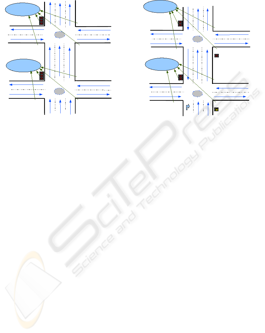
Figure 1: The Considered Area.
consider the area depicted in Fig. 1. It consists of
two traffic nodes (tn
1
and tn
2
); each traffic node rep-
resents a crossroads. The traffic flow at each traffic
node is controlled by a set of traffic lights. In details,
the traffic at the traffic nodes tn
1
and tn
2
are respec-
tively controlled by four traffic lights. Both sets of
traffic lights adopt the same synchronization protocol
(named TwoGroupsSyn): opposite traffic lights have
always the same color, if a couple is red the other one
is green or vice versa. The synchronization protocol
specifies the following groups of synchronizations:
TwoGroupsSyn((A,B), [(tf
1
, tf
3
), (tf
2
, tf
4
)])
TwoGroupsSyn((A,B), [(tf
5
, tf
7
), (tf
6
, tf
8
)])
Note that, in the considered area we have a large av-
enue (the road composed by the sections rs
2
, rs
4
and
rs
7
) with three lanes, the traffic lights steering the traf-
fic flow in this avenue have three lights as well:
tf
2
= {tf
2
L
1
, tf
2
L
2
, tf
2
L
3
}
tf
4
= {off, off, off}
tf
6
= {tf
6
L
1
, tf
6
L
2
, tf
6
L
3
}
tf
8
= {off, off, off}
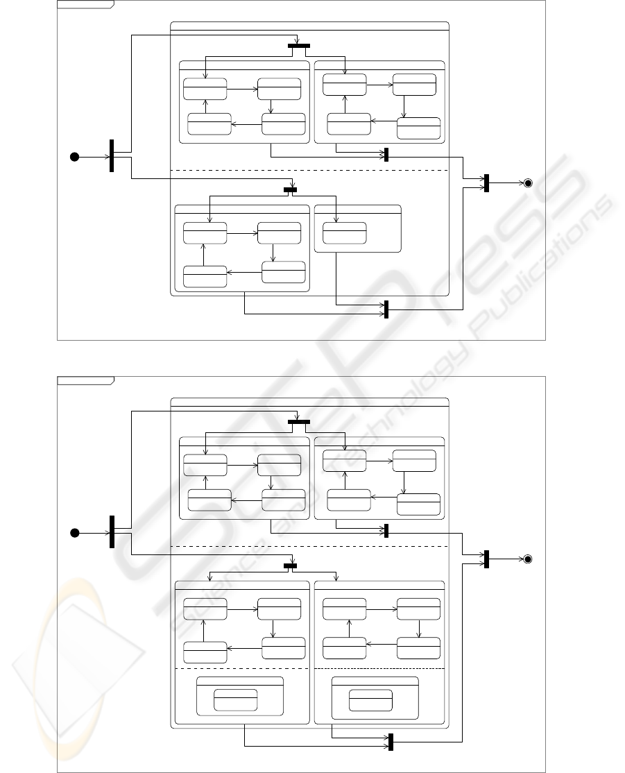
Figure 3(a) shows the statechart that describes the
traffic lights behavior (synchronization policy) at the
traffic node tn
1
.
When an anomalous situation is detected (e.g., a
traffic jam in the rush hour or a gas tube explodes)
the UTCS must adapt itself to solve or alleviate the
emergency. Of course, not all the anomalous situa-
tion can be foreseen at design-time and anyway the
code and the design should not be polluted with the
management of these anomalous and seldom cases.
tn1
tn2
TwoGroupsSync
TwoGroupsSync
rs1
rs2
rs3
rs4
rs5
rs6
rs7
tf1
tf2
tf3
tf4
tf5
tf6
tf7
tf8
Figure 2: Emergency plan.
Therefore the adaptation dynamically takes place and
consequently also the design must be changed.
Consider the case of the emergency plan, showed in
Fig. 2, for alleviating the congestion at the rush hour
in the large avenue. In the plan the first lane of the
avenue will be run in the other direction and conse-
quently some traffic lights change their behavior and
the overall synchronization protocol.
In particular the traffic lights in the large avenue are
characterize by:
tf
2
= {tf
2
L
1
, tf
2
L
2
, off}
tf
4
= {tf
4
L
1
, off, tf
2
L
2
}
tf
6
= {tf
6
L
1
, tf
6
L
2
, on/off}
tf
8
= {tf
8
L
1
, off, off}
Figure 3(b) shows the statechart that describes the
traffic lights behavior at the traffic node tn
1
after the
application of the emergency plan.
3.1 The Role of the Developer
To realize the emergency plan (Fig. 2), the UTCS
must evolve and its design information must be kept
coherent with the performed evolution.
From the point of view of the developer, the design
information must reflect the code changes necessary
to realize the emergency plan and in particular he has
to set how the design information has to change to be
consistent to adapted system. To this regard, (s)he has
to write the corresponding maintenance rules.
VIEWPOINT FOR MAINTAINING UML MODELS AGAINST APPLICATION CHANGES
265
tf3−tf1 &tf2−tf4 synchronization
tf1 states
greenYellow
green
redYellowred
t=20 sec
tick()
t=5 sectick()
t=30 sec
tick()
t=5 sec tick()
tf3 states
greenYellow green
redYellowred
t=20 sec
tick()
t=5 sectick()
t=30 sec
tick()
t=5 sec tick()
tf4 states
Off
tf2 states
offOn
off
onOffon
t=30 sec
tick()
t=5 sectick()
t=20 sec
tick()
t=5 sec tick
TwoGroupSync−4tf−4tn1
group A
turn_on()
group B
turn_on()
phase I
turn_on()
phase I
turn_off()
(a) original statechart
tf3−tf1 &tf2−tf4 synchronization
tf1 states
greenYellow
green
redYellowred
t=20 sec
tick()
t=5 sectick()
t=30 sec
tick()
t=5 sec tick()
tf3 states
greenYellow green
redYellowred
t=20 sec
tick()
t=5 sectick()
t=30 sec
tick()
t=5 sec tick()
tf4 states(tf4−lane1 | tf4−lane2&tf4−lane3)
offOn off
onOffOn
t=30 sec
tick()
t=5 sectick()
t=20 sec
tick()
t=5 sec tick()
tf4−lane2&tf4−lane3 states
off
tf2 states (tf2−lane1&tf2−lane2 | tf2−lane3)
offOn
off
onOffon
t=30 sec
tick()
t=5 sectick()
t=20 sec
tick()
t=5 sec tick
tf2−lane3 states
off
TwoGroupSync−4tf−4tn1
group A
turn_on()
group B
turn_on()
phase I
turn_on()
phase I
turn_off()
(b) adapted statechart
Figure 3: UML statecharts representing the traffic lights behavior at the traffic node tn
1
before and after the adaptation.
ICSOFT 2006 - INTERNATIONAL CONFERENCE ON SOFTWARE AND DATA TECHNOLOGIES
266
3.1.1 Maintenance Plan
The maintenance rules will apply a set of operations
to the design information that will transform them
into the design information of the evolved system. In
particular, in the considered example, the change to
the traffic lights synchronization policy at the traffic
node tn
1
implies to evolve the statechart in Fig. 3(a)
to the statechart in Fig. 3(b) and to perform some ad-
justments to the deployment diagram.
Maintenance rules for the deployment model.
The maintenance rules has to carry out the
following actions on the deployment diagram:
• turning on the traffic light tf
4
at the first lane and
off at the second and third lanes;
• turning off the traffic light tf
2
at the third lane;
• creating a new synchronization protocol:
TwoGroupsSyn((A,B), [(tf
1
, tf
3
), (tf
4
, tf
5
)])
for the changed set of traffic lights.
Maintenance rules for the statechart.
The maintenance rules has to carry out the follow-
ing actions on the statechart:
• modifying as follows the tf
2
states: (1) to change
the name of the composite state; (2) to add a new
region; (3) to add a new composite state to the
new region (tf
2
L
3
states with initial state=off;
• modifying as follows the tf
4
states: (1) to rename
the composite state; (2) to turn on the composite
state; (3) to add four states with required arcs and
label (On, onOff, off, offOn); (4) to add a new
region; (5) to add a composite state to the new
region (tf
4
L
2
and tf
4
L
3
) with initial state=off.
3.1.2 Maintenance Rules as Scripts
To automate the design information adaptation, the
described rules must be implemented as scripts (e.g.,
Ruby or Python scripts) that can be invoked during
the system evolution.
In the following we present some portions of the
Ruby scripts necessary for adapting our test case.
Once applied these scripts the design information will
reflect the code adaptation and, for example, the stat-
echart for the traffic lights synchronization will look
as the statechart in Fig. 3(b).
This code snippet adapts the synchronization be-
tween traffic lights by adding a new region at the stat-
echart with a state called "tf
4
−lane
1
states".
# add the "tf
4
−lane
1
states" to Region
1
top1.addState("tf
4
−lane
1
states")
top1SiTl4=top1.getAllSimpleState[0]
top1SiTl4.addNewRegion("tf
4
−lane
1
")
top1SiTl4r=top1SiTl4.getRegion("tf
4
−lane
1
")
This code snippet adds four states ("on",
"onOff", "off", "offOn") to the simple state
"tf
4
−lane
1
states". Then it introduces the required
transitions between states for the traffic light instance
("tf
4
−lane
1
states").
# add the transitions
top1SiTl4lane1ron =
top1SiTl4lane1r.addState("on")
top1SiTl4lane1ronOff =
top1SiTl4lane1r.addState("onOff")
top1SiTl4lane1roff =
top1SiTl4lane1r.addState("off")
top1SiTl4lane1roffOn =
top1SiTl4lane1r.addState("offOn")
top1SiTl4lane1ron.addTransitionTo
(top1SiTl4lane1ronOff, "",
"t=30 sec", "tick()")
top1SiTl4lane1ronOff.addTransitionTo
(top1SiTl4lane1roff, "",
"t=5 sec", "tick()")
top1SiTl4lane1roff.addTransitionTo
(top1SiTl4lane1ronOff, "",
"t=20 sec","tick()")
top1SiTl4lane1ronOff.addTransitionTo
(top1SiTl4lane1ron, "",
"t=5 sec", "tick()")
4 RELATED WORK
Maintenance and evolution of continuously software
systems is becoming an interesting topic of investi-
gation. Here we relate our work to research on soft-
ware evolution, UML refactoring, reflective and adap-
tive techniques to software evolution.
The methodology for defining the relation between
the what (i.e., understanding) of software evolution
and the how (i.e., control and support) of software
evolution presented in (Lehman and Ramil, 2003).
In (Lehman et al., 2002), the system dynamic model
that aids to formalize the behavioral model of the de-
velopment processes for the long-lived systems.
Refactoring techniques help to overcome the prob-
lems at the code-level by defining software transfor-
mations that restructure a software system while pre-
serving its behavior. Proposal for refactoring of UML
models presented in (Suny
´
e et al., 2001).
Maintaining the consistency between UML models
has been presented in (Van Der Straeten et al., 2003).
VIEWPOINT FOR MAINTAINING UML MODELS AGAINST APPLICATION CHANGES
267

In (Chiorean et al., 2004), the authors have presented
a practical approach to check the consistency between
UML models by using OCL based on transfer UML
model by using the standard XMI. Whereas, a method
for tracing the concurrent Java programs by using the
UML is presented in (Mehner, 2002).
In (Cazzola et al., 2004), the authors have presented
RAMSES, a reflective architecture that provides an
application with the ability to self-adapt based on its
design information. In this paper, we are describing a
framework that performs the vice versa of the RAM-
SES middleware, by keeping the design information
coherent with the self-adapting application.
In (Yoder and Johnson, 2002), the authors have pre-
sented an approach named adaptive object model that
helps both architects and developers to understand,
develop, and maintain systems. This approach pro-
vides an aspect-oriented model of the application that
can change whenever a business change is needed and
be immediately reflected on the running application.
The above approaches deal with adaptation and
transformation models, similar solutions are required
for adapting the design information of the software
systems. We consider our approach as a method, that
supports the online evolution for the design models of
the software systems.
5 CONCLUSION
In this paper we have illustrated how to maintain the
design information of the software system based on
their internal representation stored in XMI schema.
The approach permits of evolving the design informa-
tion consistently with the evolution of the application.
We have shown the applicability of the approach on a
case study.
The benefit for the proposed approach, is to save
the time and efforts and increase the performance.
The developer implements the changes in form of
script rules, and apply them to the XMI schema when
the system is evolved.
ACKNOWLEDGEMENTS
The RAMSES project is funded by the Deutsche
Forschungsgesellschaft (German Science Founda-
tion), project number SA 465/31-1.
REFERENCES
Booch, G., Rumbaugh, J., and Jacobson, I. (1999). The Uni-
fied Modeling Language User Guide. Object Technol-
ogy Series. Addison-Wesley, Reading, Massachusetts,
third edition.
Cazzola, W., Ghoneim, A., and Saake, G. (2004). Soft-
ware Evolution through Dynamic Adaptation of Its
OO Design. In Ehrich, H.-D., Meyer, J.-J., and Ryan,
M. D., editors, Objects, Agents and Features: Struc-
turing Mechanisms for Contemporary Software, Lec-
ture Notes in Computer Science 2975, pages 69–84.
Springer-Verlag, Heidelberg, Germany.
Cazzola, W., Pini, S., and Ancona, M. (2005). The Role
of Design Information in Software Evolution. In Pro-
ceedings of the 2nd ECOOP Workshop on Reflection,
AOP and Meta-Data for Software Evolution (RAM-
SE’05), in 19th European Conference on Object-
Oriented Programming (ECOOP’05), pages 59–70,
Glasgow, Scotland.
Chiorean, D., Pas¸ ca, M., C
ˆ
arcu, A., Botiza, C., and
Moldovan, S. (2004). Ensuring UML Models Consis-
tency Using the OCL Environment. Electronic Notes
Theoretical Computer Science, 102:99–110.
Lehman, M. M., Kahen, G., and Ramil, J. F. (2002). Be-
havioural Modelling of Long-Lived Evolution Pro-
cesses - Some Issues and an Example. Journal of Soft-
ware Maintenance and Evolution, 14(5):335–351.
Lehman, M. M. and Ramil, J. F. (2003). Software Evolution
- Background, Theory, Practice. Information Process-
ing Letters, 88(1-2):33–44.
Mehner, K. (2002). JaVis: A UML-Based Visualization
and Debugging Environment for Concurrent Java Pro-
grams. In Revised Lectures on Software Visualization,
International Seminar, LNCS 2269, pages 163–175,
Dagstuhl Castle, Germany. Springer.
Suny
´
e, G., Pollet, D., Le Traon, Y., and J
´
ez
´
equel, J.-M.
(2001). Refactoring UML Models. In Gogolla, M. and
Kobryn, C., editors, Proceedings of the 4th Interna-
tional Conference on the Unified Modeling Language
(
UML’01
), LNCS 2185, pages 134–148, Tor onto,
Ontario, Canada.
Van Der Straeten, R., Mens, T., Simmonds, J., and Jonck-
ers, V. (2003). Using Description Logic to Maintain
Consistency between UML Models. In Stevens, P.,
Whittle, J., and Booch, G., editors, Proceedings of the
6th International Conference on the Unified Modeling
Language (
UML’03
), LNCS 2863, pages 326–
340, San Francisco, CA, USA. Springer.
Yoder, J. W. and Johnson, R. E. (2002). The Adaptive
Object-Model Architectural Style. In Bosch, J., Gen-
tleman, W. M., Hofmeister, C., and Kuusela, J., edi-
tors, Proceedings of the 3rd Working IEEE/IFIP Con-
ference on Software Architecture (WICSA’02), vol-
ume 224 of IFIP Conference Proceedings, pages 3–
27. Kluwer.
ICSOFT 2006 - INTERNATIONAL CONFERENCE ON SOFTWARE AND DATA TECHNOLOGIES
268
