
SILHOUETTE DETECTION FOR ADAPTIVE POLYGONAL MESH
SIMPLIFICATION USING DISTANCE TRANSFORMS
Susana Mata and Luis Pastor
Dpt. de Informática, Estadística y Telemática, U. Rey Juan Carlos
C. Tulipán, s/n., 28933 Móstoles, Madrid, Spain
Angel Rodríguez
Dept. de Tecnología Fotónica, U. Politécnica de Madrid
Campus de Montegancedo s/n, 28660 Boadilla del Monte, Spain
Keywords:
Computational Geometry and Object Modelling, Three Dimensional Graphics and Realism, Picture and Image
Generation.
Abstract:
Distance Transforms have proven to be useful for many image processing applications. Nevertheless, they
have only recently started to be used in computer graphics environments. The goal of this paper is to propose
a new technique based on Distance Transforms for detecting mesh elements which are close to the objects’
external contour (from a given point of view), and using this information for weighting the approximation
error which will be tolerated during the mesh simplification process.
1 INTRODUCTION
The number of fields using three dimensional graph-
ics is constantly increasing. Different areas like medi-
cine, education, training, leisure, etc. are more and
more taking advantage of the benefits that 3D visual-
ization can bring to them.
Representing objects is one of the key stages of any
computer graphics system. Among the mainstream
models in this field, the most extended technique for
representing the surface of objects is based on polyg-
onal meshes, being the simplicity of its basic elements
one of the underlying reasons (Watt, 2000).
However, polygonal meshes need a large number
of polygons for approximating real objects with a
reasonable accuracy. Whenever computation time is
a concern, techniques which decrease the model’s
polygon count while keeping an acceptable visual
appearance are mandatory. An approach that has
been widely investigated is multiresolution mod-
elling, which consists in representing objects at dif-
ferent resolution levels and choosing the proper ap-
proximation according to the visualization conditions
(Xia and Varshney, 1996; Hoppe, 1997). Basic princi-
ples of this approach were set by James Clark (Clark,
1976); comprehensive surveys can be found at (Puppo
and Scopigno, 1997; Garland, 1999; Luebke, 2001;
Luebke et al., 2003; Floriani et al., 2004).
The key point is to obtain a simplified model us-
ing less computational resources but looking similar
to the original one when rendered under certain con-
ditions. No attention needs to be paid to features not
observable by the end user. Moreover, some details
in a model become more obvious than others to a hu-
man viewer. For example, silhouettes are known to be
critical for the final visual quality appreciated by our
visual system (Luebke and Erikson, 1997).
The goal of this paper is to propose a new tech-
nique that allows taking into account the proximity
of a mesh element to the mesh’s external contour for
weighting the approximation error which will be tol-
erated during the simplification process. More specif-
ically, the contributions of this work can be briefly
summarized as follows:
• Analyzing the applicability of Distance Transforms
for detecting the proximity of mesh elements to the
external silhouette.
• Proposing mesh simplification criteria based on
a precomputed silhouette proximity measure, ob-
tained by means of a Distance Transform.
• Presenting a simplification technique using a Dis-
tance Transform for selecting the allowed approxi-
mation error in regions close to the external silhou-
ette.
The rest of the paper is organized as follows: Sec-
tion 2 presents a short overview of some previous
work related to mesh simplification algorithms and
the different approaches to identify and preserve the
model’s silhouette. A brief introduction to basic
43
Mata S., Pastor L. and Rodríguez A. (2006).
SILHOUETTE DETECTION FOR ADAPTIVE POLYGONAL MESH SIMPLIFICATION USING DISTANCE TRANSFORMS.
In Proceedings of the First International Conference on Computer Graphics Theory and Applications, pages 43-50
DOI: 10.5220/0001353800430050
Copyright
c
SciTePress

concepts of digital Distance Transforms and Multi-
Tessellation is also included. Section 3 describes the
proposed approach, while Section 4 shows some ex-
perimental results. Finally the conclusions and future
work are presented in Section 5.
2 PREVIOUS WORK
2.1 Mesh Simplification
Many mesh simplification techniques have been pro-
posed during the last years. Among the methods
based on objective metrics, work has been done in or-
der to incorporate other attributes besides geometry
like color, texture or normals (Garland and Heckbert,
1998; Cohen et al., 1998). Perceptual metrics have
also been developed (O’Sullivan et al., 2004; Cheng
and Boulanger, 2005); Lindstrom and Turk use an im-
age metric to guide the simplification process (Lind-
strom and Turk, 2000). Reddy introduced a percep-
tive model to guide the selection of the appropriate
level of detail (Reddy, 1997). (Luebke, 1998) de-
fined a contrast sensitivity function that predicts the
perception of visual stimuli. Some of the perceptu-
ally driven simplification methods explicitly pursue a
good silhouette preservation, defining normal cones
(Williams et al., 2003). Good silhouette approxi-
mation through contour computation in image space
has also been researched (Raskar and Cohen, 1999;
Sander et al., 2000).
The approach presented here not only identifies the
objects’ silhouette. It performs also a mesh elements’
explicit classification in object space, attending to its
proximity to the external contour from a given point
of view.
2.2 Digital Distance Transforms
Measuring the distance between image elements may
be of interest for further processing in many image
analysis applications. Basics concepts regarding dig-
ital distances can be found in (Rosendfeld and Pflatz,
1966; Rosendfeld and Pflatz, 1968).
The application of a Distance Transform to an im-
age (usually binary) produces as output a distance
image, where each element of this distance-image is
assigned a distance label. For any element its label
stores a value indicating its closest distance to the
background. Therefore, the computed distance image
can be seen as a grey-level image where the intensity
level identifies the minimum distance to the comple-
ment of the object.
A distance transform can be computed in two steps
by propagating local distances over the image; this is
true for 2D, 3D and higher dimensions (Rosendfeld
and Pflatz, 1966). Initially, the elements belonging to
the object are set to infinity and the elements belong-
ing to the background are set to 0. In the case of a
2D image, during the first step the image is analyzed
from top to bottom and from left to right. During
the second step, the image elements are visited from
right to left and from bottom to top. Each element
is assigned the minimum value between itself and the
already visited neighbours incremented by their con-
nectivity weight.
Distance transforms and some variations of them
in combination with other image processing tech-
niques can be applied for representing and analyzing
3D objects in multiple applications (Nystrom, 1997;
Svensson, 2001; Sintorn, 2005). Distance fields have
also been applied in computer graphics environments,
such as in collision detection (Teschner et al., 2004).
However, digital distance transforms can be used
in other fields that have not been explored so far. The
work presented here aims to open a way for new ap-
plications of Distance Transforms within computer
graphics environments.
2.3 Multi-Tessellation
The Multi-Tessellation method, originally called
Multi-Triangulation, was introduced by De Floriani et
al. (Floriani et al., 1997). It provides a general mul-
tiresolution framework for polygonal meshes offering
several attractive features, like selective refinement,
locality or dynamic update (Floriani et al., 1998).
Multi-Tessellation, MT for short, is a hierarchical
model defined as a directed acyclic graph, where the
nodes represent mesh updates and arcs represent de-
pendencies between updates labelled with sets of tri-
angles. Each triangle t may have associated a global
approximation error, describing the difference be-
tween t and the surface patch it approximates. Simpli-
fication applications may be adapted in order to build
an MT while performing the simplification process.
Once the MT has been built, it can be queried at run
time for extracting a simplified mesh fulfilling some
defined restrictions.
Two kinds of criteria can be defined for selectively
refining the mesh:
• A threshold function, used to bound the approxi-
mation error.
• A focus condition, used to set the region of interest
under which the query will be evaluated.
The distributed package (Geometric Modeling and
Computer Graphics Research Group. DISI - Dipar-
timento di Informatica e Scienze dell’Informazione
University of Genova, 2005) implements a hierarchy
of classes that permit the construction of an MT by
adapting a simplification method in order to perform
some basic MT operations. Some useful threshold
GRAPP 2006 - COMPUTER GRAPHICS THEORY AND APPLICATIONS
44

and focus conditions are already implemented, in-
cluding point location, region intersection, etc. Ad-
ditionally, an executable implementing the Jade sim-
plification technique is provided (Ciampalini et al.,
1997). In this case, the simplification algorithm is
based on vertex decimation operators.
Defining new focus and threshold conditions can be
easily done by adding new classes to the library. This
sets a general and useful framework for dynamically
managing the level of detail of a particular represen-
tation.
The MT package has been used in this work to
present the results obtained by integrating the pre-
computed distance to silhouette into the threshold
function.
3 METHOD DESCRIPTION
The approach followed here classifies the mesh faces
or vertices attending to their proximity to the external
silhouette from a certain point of view. The classifi-
cation process uses a Distance Transform, computed
over the mesh elements’ projection on the visualiza-
tion plane. This transform provides for each element
its distance to the projected contour, being useful for
extracting the mesh elements which compose or are
located near the mesh silhouette for any particular
point of view.
Previous to the projection stage, a 2D grid is cre-
ated on the visualization plane. This grid needs a res-
olution level that has to be selected according to the
input mesh level of detail, the desired simplification
degree and the available time to perform the simpli-
fication procedure. Every cell in the 2D grid has a
list associated containing the indexes of the faces that
project into it. The occupancy of the grid cells can be
represented as a binary image; it is over this binary
image where Distance Transforms can be computed.
Last, a classification of the model faces can be ob-
tained backprojecting the distance labels to the mesh
faces that map into each grid cell.
The same process can be applied for backproject-
ing the distance values to the vertices instead of to the
faces. The tags assigned to the polygonal mesh ele-
ments can then be used in different ways to guide the
simplification process, providing a criterion for modi-
fying locally the approximation error allowed in areas
close to the external contour.
It must be highlighted that the first three steps are
performed in a pre-processing stage, producing a la-
belled polygonal mesh which will be used later on
during the simplification stage. The following Sec-
tions describe each of the method’s stages.
3.1 Mesh Mapping
Silhouettes are view-dependent features. For that rea-
son, their extraction must be done for a certain view
point. Given a visualization plane, the 3D mesh is
projected on it by applying the proper projection ma-
trix to each vertex coordinates. In order to extract the
object’s silhouette, it is necessary to create a binary
image where distance measurements can be carried
out. For that purpose the visualization plane is parti-
tioned into cells forming a grid which can be seen as
a 2D digital image. The number of cells making up
the grid is analogous to the image resolution; conse-
quently the parameterization of this value allows the
analysis at different resolutions.
Every face belonging to the projected polygonal
mesh is tested to find the cells of the 2D grid with
which it intersects.
A data structure is updated where every grid ele-
ment keeps track of the faces intersecting with it. This
way, the posterior backprojection of distance values
is straightforward. This procedure is computationally
expensive, but affordable as pre-processing.
The binary image is extracted from the grid occu-
pancy information, setting as object every cell with
any face mapping over it.
3.2 Distance Transform
Computation
Once the 2D image is obtained, the next stage consists
in obtaining a distance image by applying a distance
transform to the binary image. The result is a new
image where the assigned intensity values increase as
the pixel gets further away from the background.
3.3 Mesh Labelling
At this point, the distance of an object pixel to the
background has already been computed. Previously,
the correspondences between pixels and the facets
mapping into them have also been calculated. There-
fore, the labelling of every face with a value repre-
senting its distance from the background is a simple
process. The distance label of a pixel, which is equiv-
alent to a grid cell, is assigned to all the faces that
intersect with the cell.
As a result, a labelled mesh is obtained where every
face stores a value representing its proximity to the
external contour.
The same approach may be followed when the dis-
tance label is assigned to vertices or edges instead of
faces. Figure 1 shows the results of backprojecting
the distance values onto the mesh. Fig. 1(a) shows
a rendered view of the original mesh. Fig. 1(b) and
1(c) represent the same mesh under different points of
SILHOUETTE DETECTION FOR ADAPTIVE POLYGONAL MESH SIMPLIFICATION USING DISTANCE
TRANSFORMS
45
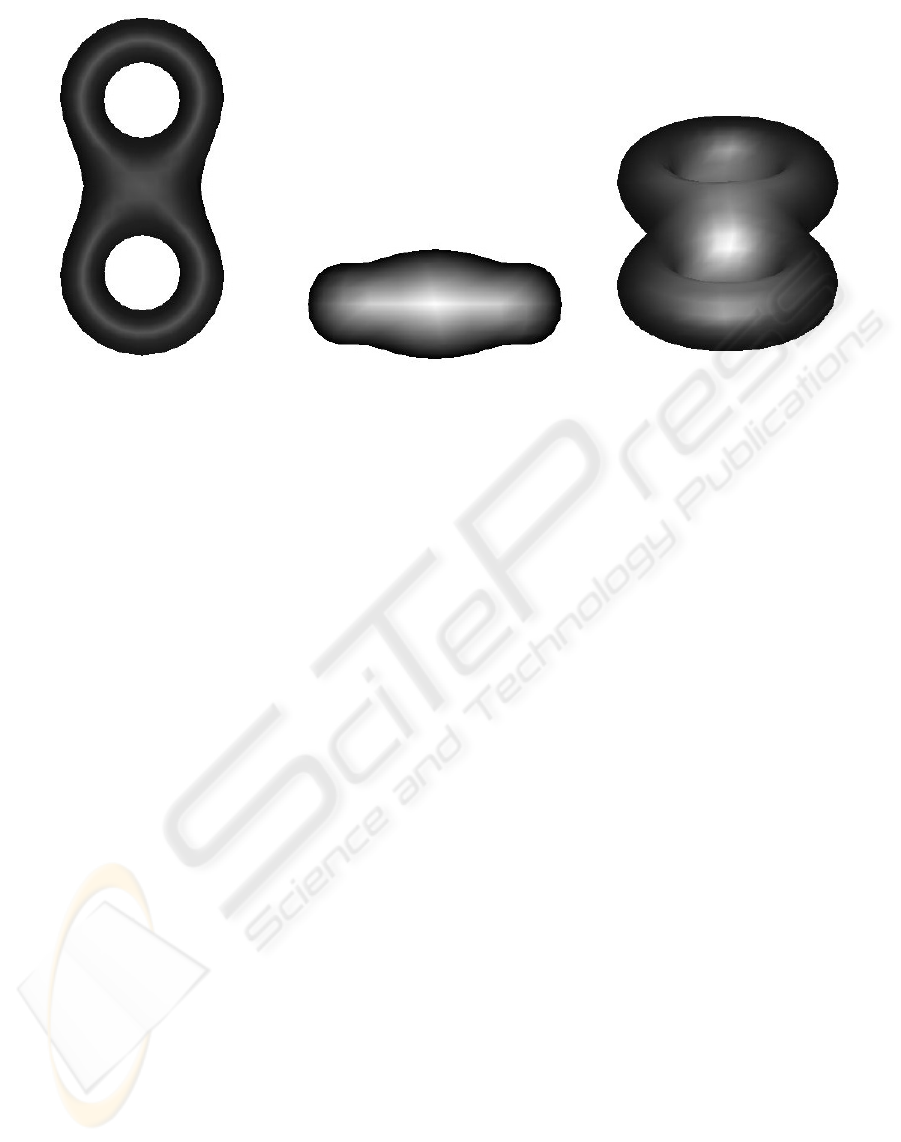
(a) Original mesh (b) Mesh in Figure 1(a) rotated 180 de-
grees over the X axis, with grey levels
proportional to the distances to the ex-
ternal silhouette
(c) Mesh in 1(a) rotated 205 degrees
over the X axis, with grey levels propor-
tional to the distances to the external sil-
houette
Figure 1: Backprojection of distance values in image 1(a) over the 3D model. Mesh vertices color represent the backprojected
distance label.
view. The grey levels in the images represent distance
to the silhouette (lighter intensities represent higher
distances to the contour).
3.4 Mesh Simplification
The method’s last stage is also the final goal of the
whole process, where the extracted distance values
are used for mesh simplification purposes.
The use of the distance labels depends on the se-
lected simplification technique. The work presented
here has been based on the Jade approach, a ver-
tex decimation technique based on the global er-
ror (Ciampalini et al., 1997). The distance infor-
mation is computed for the vertices of the original
mesh. Since the vertices belonging to a simplified
model are a subset of the original mesh, the precom-
puted distance labels are valid for any level of detail.
Multi-Tessellations obtained through the application
of the Jade method are freely distributed with the MT-
Package.
The proximity of every facet to the external con-
tour is taken into account in the extraction stage. This
means that for a given error threshold, the error al-
lowed in regions close to the external silhouette is re-
duced according to a predefined law.
The implemented solution, requires the definition
of two parameters:
• Distance interval: range of distance labels which
identify the region where a more accurate approxi-
mation is desired.
• Error factor: the purpose of this parameter is to de-
fine an error threshold for the portion of the mesh
within the region of interest. This threshold, differ-
ent from the global error threshold, is defined as a
function of the global error threshold.
The width of the contour area can be simply modi-
fied by changing the range of distance labels that de-
fine the region of interest. In our case, the range is
defined by setting a threshold over the minimum dis-
tance of the vertices belonging to a face. Other solu-
tions can be easily devised.
The error factor allows to refine the quality of the
approximation in the contour region taking into ac-
count the threshold error fixed for the rest of the
model. This way, the allowed error in the contour
is f · e, where e is the error permitted in the rest of
the model and f is the error factor. Again, other error
functions are also feasible.
4 RESULTS
The experimental results presented in this section
were obtained by applying the technique previously
described to the Multi-Tessellation models distributed
together with the MT-Package.
Figure 2(a) shows the simplification of the mesh
obtained by imposing a restrictive error threshold over
the silhouette. In this case, the error factor was set to
0, meaning that no error is allowed on the external
GRAPP 2006 - COMPUTER GRAPHICS THEORY AND APPLICATIONS
46
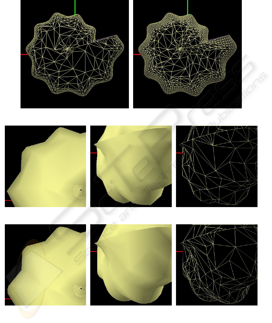
(a) Result of simplifying mesh elements with dis-
tance values larger than 2
(b) Result of simplifying mesh elements with dis-
tance values larger than 15
(c) Close-up view after the Jade sim-
plification
(d) The same simplified mesh from an-
other point of view
(e) Wire mesh of 2(d)
(f) Close-up view after the Distance
Transform based simplification
(g) A Distance Transform based sim-
plification for a different point of view
(h) Wire mesh of 2(g)
Figure 2: Shell example.
SILHOUETTE DETECTION FOR ADAPTIVE POLYGONAL MESH SIMPLIFICATION USING DISTANCE
TRANSFORMS
47
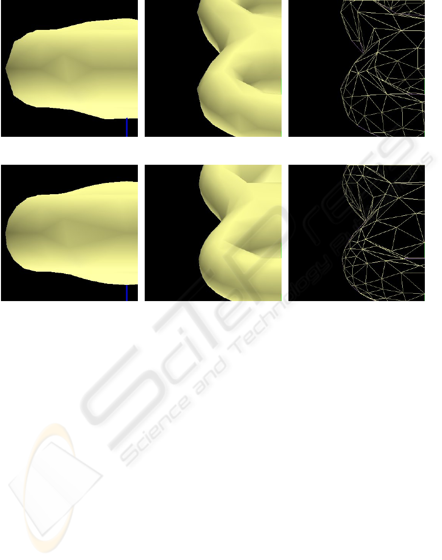
(a) Close-up view of the mesh simpli-
fied with the Jade method
(b) Another perspective of the result af-
ter the Jade simplification
(c) Wire mesh of 3(b)
(d) Close-up view of the mesh simpli-
fied with proposed method
(e) A Distance Transform based simpli-
fication for a different point of view
(f) Wire mesh of 3(e)
Figure 3: Abstract geometric example.
contour. The region of interest (the mesh portion con-
sidered to be near the silhouette) is made up of faces
whose vertices have a minimum distance label less
than or equal to 2. It can be seen that the rest of the
mesh is coarser (it has suffered a strong simplifica-
tion process), while the density of triangles over the
silhouette is extremely high.
The algorithm presented here allows an easy para-
meterization of the width of the contour area, as it can
be appreciated in Figure 2(b). It can be seen how the
region of high resolution extends itself towards the in-
terior of the object.
Figures 2(c) and 2(f) show two simplified meshes
with approximately the same number of polygons,
1074 and 1077 respectively, obtained with two meth-
ods: the Jade and the distance-based approach pro-
posed here. Figures 2(d) and 2(g) show the simpli-
fication from a different point of view. Figure 2(d)
(1226 triangles) has been obtained from Jade simpli-
fication, while Figure 2(g) has been obtained using
the distance information. A perceptible improvement
in the smoothness of the silhouette can be appreciated
in both Fig. 2(f) and 2(g). A wireframe rendering of
the model reveals a higher density of facets close to
the external contour in Fig. 2(h) with respect to 2(e).
Figure 3 shows some results of simplifications ap-
plied to the model shown in Fig. 1(a). Figure 3(a)
(612 triangles) is the simplified model extracted from
Jade simplification method, while Fig. 3(d) (600 tri-
angles) represents the simplification using distance
information. Under a different rotation, the simpli-
fication is carried out using distance labels in 3(e)
(510 triangles) while in Fig. 3(b) (508 triangles) no
distance information is taken into account. Again,
the smoothness of the silhouette is higher with our
method and the mesh density increases in the prox-
imity of the external contour, as shown in Fig. 3(c)
(without distance information) and 3(f) (with distance
information).
It can be observed that the approximation in the sil-
houette is noticeable better with our method.
Regarding computational issues, cost in terms of
memory requirements is only of one extra value per
vertex. In case of tagging the mesh faces or mesh
edges an additional value per tagged element would
be required. With respect to computational cost, it
GRAPP 2006 - COMPUTER GRAPHICS THEORY AND APPLICATIONS
48

has to be noted that all the heavy computation is per-
formed at pre-processing time. The most expensive
step is the mesh mapping over the 2D grid, in or-
der to collect the information needed for backproject-
ing the distance values. Efficient implementations for
these operations using spatial data partitioning could
be considered. As it was explained above, the com-
putation of the Distance Transform can be performed
involving only two passes over the 2D image.
5 CONCLUSIONS AND FUTURE
WORK
Simplification algorithms are usually guided by some
criteria in order to select which elements of the
mesh shall be removed or replaced. Introducing
precomputed distance labels as part of the guiding
metrics is a straightforward process, opening a new
way to design a range of techniques which are use-
ful for including perceptually motivated criteria in
mesh simplification algorithms. The results presented
here suggest that the use of distance information is
a promising approach for mesh simplification tech-
niques, since adding distance labels to mesh ele-
ments provides more information than the conven-
tional methods based on the extraction of the silhou-
ette edges.
The fact that distance information can be assigned
to any element of the mesh (vertices, edges or faces)
facilitates adapting these techniques to a wide range
of simplification methods. The nature of the basic un-
derlying operator (vertex removal, edge collapse, etc)
does not impose additional limitations. Furthermore,
the applicability of distance labels goes from off-line
simplification processing to run-time selective refine-
ment.
The work presented here computes the mesh ele-
ments’ distance to the extended contour given a pre-
defined point of view. Future work includes:
• Extending the method for covering all possible
points of view in a way which is both performant
and computationally efficient.
• Integrating distance to the silhouette into other
mesh simplification methods besides the Jade
method.
• Extending the method in order to consider also in-
ternal silhouettes.
ACKNOWLEDGMENTS
This work has been partially funded by the Span-
ish Ministry of Education and Science (grant
TIC2003-08933-C02) and Government of the Com-
munity of Madrid (grants GR/SAL/0940/2004 and S-
0505/DPI/0235).
The authors also thank to the Geometric Modelling
and Computer Graphics Research Group for distrib-
uting the MT-Package.
REFERENCES
Cheng, I. and Boulanger, P. (2005). A 3D perceptual met-
ric using just-noticeable-difference. In Proc. of Euro-
graphics 2005.
Ciampalini, A., Cignoni, P., Montani, C., and Scopigno, R.
(1997). Multiresolution decimation based on global
error. In The Visual Computer, volume 13 of 5, pages
228–246.
Clark, J. H. (1976). Hierarchical geometric models for visi-
ble surface algorithms. Communications of the ACM,
19:547–554.
Cohen, J., Olano, M., and Manocha, D. (1998).
Appearance-preserving simplification. InProceedings
of SIGGRAPH 98, pages 115–122.
Floriani, L. D., Kobbelt, L., and Puppo, E. (2004). A
survey on data structures for level-of-detail models.
In N.Dodgson, M.Floater, and M.Sabin, editors, Pro-
ceedings MINGLE Workshop 2004. Springer Verlag.
(to appear).
Floriani, L. D., Magillo, P., and Puppo, E. (1997). Building
and traversing a surface at variable resolution. In Pro-
ceedings of IEEE Visualization 97, pages 103–110.
Floriani, L. D., Magillo, P., and Puppo, E. (1998). Efficient
implementation of multi-triangulations. In Proceed-
ings of IEEE Visualization 98, pages 43–50.
Garland, M. (1999). Multiresolution modeling: Survey &
future opportunities. In EUROGRAPHICS’99.
Garland, M. and Heckbert, P. (1998). Simplifying surfaces
with color and texture using quadric error metrics.
In Proceedings of IEEE Visualization’98, pages 263–
270.
Geometric Modeling and Computer Graphics Research
Group. DISI - Dipartimento di Informatica e Scienze
dell’Informazione University of Genova (2005). The
MT (Multi-Tesselation) Package. Web.
Hoppe, H. (1997). View-dependent refinement of progres-
sive meshes. In SIGGRAPH’97, Computer Graphics
Annual Conference Series, pages 189–198. ACM.
Lindstrom, P. and Turk, G. (2000). Image-driven simplifi-
cation. In ACM Transactions on Graphics, volume 19
of 3, pages 204–241.
Luebke, D. and Erikson, C. (1997). View-dependent sim-
plification of arbitrary polygonal enviroments. In Pro-
ceedings of SIGGRAPH 97.
Luebke, D., Reddy, M., Cohen, J. D., Varshney, A., Watson,
B., and Huebner, R. (2003). Level of Detail for 3D
Graphics. Morgan Kauffmann.
SILHOUETTE DETECTION FOR ADAPTIVE POLYGONAL MESH SIMPLIFICATION USING DISTANCE
TRANSFORMS
49

Luebke, D. P. (1998). View-dependent simplification of ar-
bitrary polygonal environments. Ph. D. dissertation,
University of North Carolina.
Luebke, D. P. (May/June 2001). A developer’s survey of
polygonal simplification algorithms. IEEE Computer
Graphics and Applications. Faltan las páginas y el
volumen.
Nystrom, I. (1997). On Quantitative Shape Analysis of Dig-
ital Volume Images. Ph. D. dissertation, Uppsala Uni-
versity.
O’Sullivan, C., Howlett, S., Morvan, Y., McDonnell, R.,
and O’Conor, K. (2004). Perceptually adaptive graph-
ics. In Schlick, C. and Purgathofer, W., editors, Eu-
rographics State-of-the-Art Report (EG-STAR), vol-
ume 6, pages 141–164. Eurographics Association, Eu-
rographics Association.
Puppo, E. and Scopigno, R. (1997). Simplification, LOD
and multiresolution principles and applications. In
Fellner, D. and Szirmay-Kalos, L., editors, EURO-
GRAPHICS’97, volume16. Tutorial Notes PS97 TN4.
Raskar, R. and Cohen, M. (1999). Image precision sil-
houette edges. In 1999 Symposium on Interactive 3D
Graphics.
Reddy, M. (1997). Perceptually Modulated Level of Detail
for Virtual Environments. Ph. D. dissertation, Univer-
sity of Edinburgh.
Rosendfeld, A. and Pflatz, J. (1966). Sequential operations
in digital picture processing. Journal of the Associa-
tion for Computing Machinery, 13(4):471–491.
Rosendfeld, A. and Pflatz, J. (1968). Distance functions on
digital pictures. Pattern Recognition, 1:33–61.
Sander, P. V., Gu, X., Gortler, S., Hoppe, H., and Snyder, J.
(2000). Silhouette clipping. In Proceedings of SIG-
GRAPH 2000, pages 327–334.
Sintorn, I.-M. (2005). Segmentation Metohdos and Shape
Descriptions in Digital Images. Ph. D. dissertation,
Swedish University of Agricultural Sciences.
Svensson, S. (2001). Representing and Analyzing 3D Digi-
tal Shape Using Distance Information. Ph. D. disser-
tation, Swedish University of Agricultural Sciences.
Teschner, M., Kimmerle, S., Zachmann, G., Heidelberger,
B., Raghupathi, L., Fuhrmann, A., Cani, M.-P., Faure,
F., Magnetat-Thalmann, N., and Strasser, W. (2004).
Collision detection for deformable objects. In Eu-
rographics State-of-the-Art Report (EG-STAR), pages
119–139. Eurographics Association, Eurographics
Association.
Watt, A. (2000). 3D Computer Graphics. Addison-Wesley.
Williams, N., Luebke, D., Cohen, J. D., Kelley, M., and
Schubert, B. (2003). Perceptually guided simplifica-
tion of lit, textured meshes. In Proceedings of the
2003 Symposium on Interactive 3D Graphics, pages
113–121.
Xia, J. C. and Varshney, A. (1996). Dynamic view-
dependent simplification for polygonal models. In
Yagel, R. and Nielson, G. M., editors, IEEE Visual-
ization ’96, pages 335–344.
GRAPP 2006 - COMPUTER GRAPHICS THEORY AND APPLICATIONS
50
