
SYSTEM ARCHITECTURE OF A MIXED REALITY FRAMEWORK
Helmut Seibert
Computer Graphics Center (ZGDV), Department Visual Computing
Fraunhoferstrasse 5, 64283 Darmstadt, Germany
Patrick D
¨
ahne
Computer Graphics Center (ZGDV), Department Visual Computing
Fraunhoferstrasse 5, 64283 Darmstadt, Germany
Keywords:
Mixed Reality framework, Augmented Reality, data-flow management, distributed systems.
Abstract:
In this paper the software architecture of a framework which simplifies the development of applications in
the area of Virtual and Augmented Reality is presented. It is based on VRML/X3D to enable rendering of
audio-visual information. We extended our VRML rendering system by a device management system that is
based on the concept of a data-flow graph. The aim of the system is to create Mixed Reality (MR) applications
simply by plugging together small prefabricated software components, instead of compiling monolithic C++
applications. The flexibility and the advantages of the presented framework are explained on the basis of an
exemplary implementation of a classic Augmented Reality application and its extension to a collaborative
remote expert scenario.
1 INTRODUCTION
Creating Mixed Reality (MR) applications currently
is one of the most challenging tasks in the field of
computer graphics. The developer has to deal with
exotic hardware devices like head mounted displays,
GPS receivers, electronic compasses etc. In many
cases, especially when building mobile systems, tra-
ditional IO devices like keyboards and mice are not
available. No widely adopted standards exist in this
area.
Our own experience with different projects has
shown that most MR applications are closely tied to
the hardware they have been developed for. It is usu-
ally not a trivial task to switch from a video-see-
trough head mounted display to a system based on
a web pad, or to exchange an electromagnetic track-
ing system by a video-based tracking system. In most
cases, changing the system configuration results in
rewriting major parts of the MR application.
Another problem is that hardware platforms for
MR applications are becoming more and more hetero-
geneous. Mobile AR applications for example are not
necessarily limited to the usual Wintel platform (MS
Windows operating system on an Intel microproces-
sor), instead, new hardware platforms like handheld
PCs, handheld game consoles and mobile phones are
emerging. The broad range of different hardware
configurations and operating systems on these kinds
of devices makes cross-platform development even
worse.
Obviously, this situation is not very satisfactory and
hinders the introduction of commercial MR applica-
tions. For this reason, we developed a framework that
allows us to separate the hardware-independent appli-
cation logic from the parts of the software that de-
pend on the hardware configuration. Our framework
allows to develop MR applications by using VRML
and a special markup language used to describe the
hardware configuration. Applications written in these
markup languages are completly platform indepen-
dent, i.e. they can be executed on any platform the
runtime system has been ported to. Changing the
hardware configuration can be simply done by modi-
fying text files without the need to recompile any ap-
plication code. The main focus of our system is rapid
prototyping, i.e. it is meant to be a research system
that allows to rapidly develop small applications that
serve as a test bed for new algorithms.
2 RELATED WORK
The main research focus in the area of Augmented
Reality has been the determination of the user’s posi-
tion and orientation (tracking), appropriate interaction
200
Seibert H. and Dähne P. (2006).
SYSTEM ARCHITECTURE OF A MIXED REALITY FRAMEWORK.
In Proceedings of the First International Conference on Computer Graphics Theory and Applications, pages 200-207
DOI: 10.5220/0001354902000207
Copyright
c
SciTePress

methods for AR applications, graphical problems like
the correct illumination of virtual objects and the oc-
clusion of virtual objects by real objects, and the de-
velopment of powerful and yet lightweight wearable
computers. But recently, the development of AR soft-
ware frameworks gained more and more attention.
An early example of a software framework is CO-
TERIE (MacIntyre and Feiner, 1996). COTERIE is
a set of packages written in Modula-3 that allow to
create “Distributed shared objects”, i.e. data objects
that are transparently shared by processes on different
machines in the network.
Another well-known software-framework is
Studierstube (Schmalstieg et al., 2002). Studierstube
is based on the concept of a distributed scene graph
(Distributed Open Inventor), and a data flow frame-
work called OpenTracker (Reitmayr and Schmalstieg,
2001) that handles different kinds of trackers.
DWARF (Bauer et al., 2001) is using a concept
similar to our own concept described in this paper.
AR applications are build by using services that form
a distributed data flow graph. CORBA is used for all
network communication.
Tinmith (Piekarski and Thomas, 2003) is using an
object store based on Unix file system semantics. Ap-
plications can register callbacks on these objects to
get notifications when an object changes. Objects are
automatically distributed between different processes
on the network.
ImageTclAR (Owen et al., 2003) is an AR frame-
work based on Tcl/Tk. The basic runtime system of
the Tcl script language has been extended by modules
that provide functionality typically needed by AR ap-
plications, e.g. access to video cameras and tracking
devices.
Other software frameworks that focus on the de-
velopment of VR applications are VR Juggler (Cruz-
Neira et al., 2002) and DIVERSE (Arsenault and
Kelso, 2002). VRPN (Taylor et al., 2001) and IDEAL
(Fr
¨
ohlich and Roth, 2000) are device management
systems that concentrate on the flexible and network-
transparent access to VR devices.
Our framework differs from these existing solu-
tions in the way it is used to create MR applications.
Our system is not a library that has to be linked into
the application code, instead it is a runtime system
that allows to interpret MR applications written in a
set of markup languages. The major advantage of this
approach is that applications are platform indepen-
dent – the applications run on all platforms the run-
time system has been ported to. Furthermore, chang-
ing the hardware configuration can be easily done by
modifying simple text files, without having to recom-
pile any code. Our system shares these advantages
with ImageTclAR, which also allows to develop ap-
plications in a scripting language. In contrast to Im-
ageTclAR, our system is based on the concept of a
data flow graph, which in our opinion better reflects
the event-driven nature of MR applications than a pro-
cedural script language.
3 CONCEPT OF AN MR
FRAMEWORK
As already mentioned in the introduction, our aim is
to create MR applications that can be implemented
without much effort, and can be easily ported to mis-
cellaneous hardware configurations. The application
logic should be clearly separated from the code nec-
essary to handle hardware devices. Instead of creat-
ing large, monolithic C++ applications that have to
be recompiled each time the hardware configuration
changes, we prefer to have a set of small, reuseable
software components that are not hard-wired, but can
be easily reconfigured by using configuration files that
can be adapted to the specific system configuration.
The final aim is to create some kind of a runtime sys-
tem that is able to load and execute MR applications
written in a device- and system-independent markup
language.
When analyzing existing standards and techniques
in the computer graphics area, we realized that at least
for VR applications the VRML standard to a large
degree fulfills our needs. VRML is a markup lan-
guage that allows to describe the virtual scene in a
completely device-independent manner. Besides the
classical scene graph, VRML also allows to specify
the behavior of the virtual objects. Each node of the
scene graph is a small state machine that is able to
receive events, change its state, and to send events
depending on the state transition. In fact, the scene
graph is supplemented by a data flow graph that con-
tains the application logic. When it is not possible
to implement the application logic by using standard
nodes, the set of VRML nodes can be extended by
using “Script” nodes whose behavior can be imple-
mented in JavaScript or Java.
Because VRML perfectly fits to our requirements,
our framework is based on VRML. But VRML has
its weaknesses when used for MR applications. It is
designed for Internet applications, i.e. for VR appli-
cations running on a desktop PC equipped with stan-
dard IO devices like mice and keyboards. It does not
provide any means to integrate any devices and me-
dia used for MR applications, i.e. tracking systems or
live video streams. Therefore, we had to extend our
VRML framework by a device management system.
Most existing device management systems allow
the application to access devices by using a set of ab-
stract device classes, for example “Locator” for track-
ing systems. But only few provide means to process
the data values, e.g. to transform position values of
SYSTEM ARCHITECTURE OF A MIXED REALITY FRAMEWORK
201

tracking systems into another coordinate system, or
to calculate the position and orientation of the user by
using video images.
When we planned the architecture of our device
management system, we realized that almost all de-
vices used in MR applications produce or consume
data streams. We have live video and audio streams
from cameras and microphones, streams of position
and orientation values from tracking systems, as well
as button-press and -release events from gamepads or
keyboards. Our demand for extensive preprocessing
of data streams resulted in the concept of a data flow
graph. In this graph, we have nodes that produce data
streams (input devices), nodes that transform data
streams, and nodes that consume data streams (output
devices). Nodes send data values via “Outslots” and
receive values via “Inslots”. Like in VRML, outslots
and inslots are connected by “Routes”. The follow-
ing sections describe the components of the data flow
graph in more detail.
3.1 Nodes
Nodes are the core component of the data flow graph.
There are four types of nodes:
1. Nodes that produce data. These are usually de-
vice drivers of input devices, nodes that replay data
streams stored on a hard disk, timers etc.
2. Nodes that transform data. Examples are nodes
that transform coordinate systems, or video track-
ing systems that take video frames and transform
them to position and orientation values.
3. Nodes that consume data. These are usually de-
vice drivers of output devices, nodes that store data
streams on a hard disk, etc.
4. Nodes that do not deal with data in any way. This
sounds strange at a first glance, but our system cur-
rently already has three nodes of this kind: The
“Network” node that makes the system network
transparent, the “Web” node that provides a user
interface to the framework, and the “Inline” node
that allows to integrate subgraphs stored in config-
uration files.
To create a new node, the developer has to de-
rive a new class from the abstract node base class.
Nodes can be linked into the application executable
(mostly used for the basic, application-independent
set of standard nodes provided by the system), or they
can be loaded as plugins during runtime (application-
specific nodes).
An important design decision that has to be made
by the developer of a new node is whether the node
uses its own thread or not. Device driver nodes for
input devices usually always need to have an own
thread, because they have to listen to the port the de-
vice is connected to. All other types of nodes do not
necessarily need to have their own thread. For ex-
ample, filter nodes that transform position values into
another coordinate system usually directly calculate
the new values when they are notified that new data is
available. This means that they are in fact driven by
the threads of the device driver nodes that provided
the incoming data values. On the other hand, filter
nodes that have to perform complex calculations, like
video trackers, usually get their own threads.
3.2 Outslots and Inslots
Outslots and inslots are the means used by nodes to
exchange data values. Outslots are used to send data
to other nodes, and inslots are used to receive data
from other nodes. Both outslots and inslots are typed,
i.e. you have to specify what kind of data can be
send to or received from the slot when you create
it. When a node writes data values into an outslot,
the outslot automatically transfers copies of these data
values to all inslots it is currently connected to. For
efficiency reasons, smart pointers are used to transfer
large amounts of data, i.e. copying data values into
inslots usually just requires to copy a pointer.
For example,the Joystick node consists of two float
outslots for the two axes of the joystick, and a boolean
outslot for the button. Please note that the actual num-
ber of outslots depends on the joystick hardware de-
tected by the joystick driver, i.e. the number of float
outslots corresponds to number of axes provided by
the joystick, and the number of boolean outslots cor-
responds to the number of buttons.
3.3 Routes
When creating nodes of the data flow graph, the ap-
plication developer has to specify a unique name for
each of these nodes, e.g. “Joystick 1” and “Joystick
2” for two nodes that operate joysticks attached to the
system. Each outslot and inslot of a node has a unique
label as well, e.g. “Button #1” for the first button of a
joystick or “X-Axis” for the x-axis. As a result, each
slot in the system can be identified by a unique label
consisting of the node name and the slot name, e.g.
“Joystick 1/Button #1” for the first button of the first
joystick or “Joystick 2/X-Axis” for the x-axis of the
second joystick. To connect an outslot to an inslot, the
application developer simply has to create a so-called
“Route” that maps the label of an outslot to the label
of an inslot. Of course, only slots sending and receiv-
ing the same data type can be connected by routes.
GRAPP 2006 - COMPUTER GRAPHICS THEORY AND APPLICATIONS
202
Network
Node A
Node B
Node C
Graph 1
Proxy A
Proxy B
Node D
Graph 2
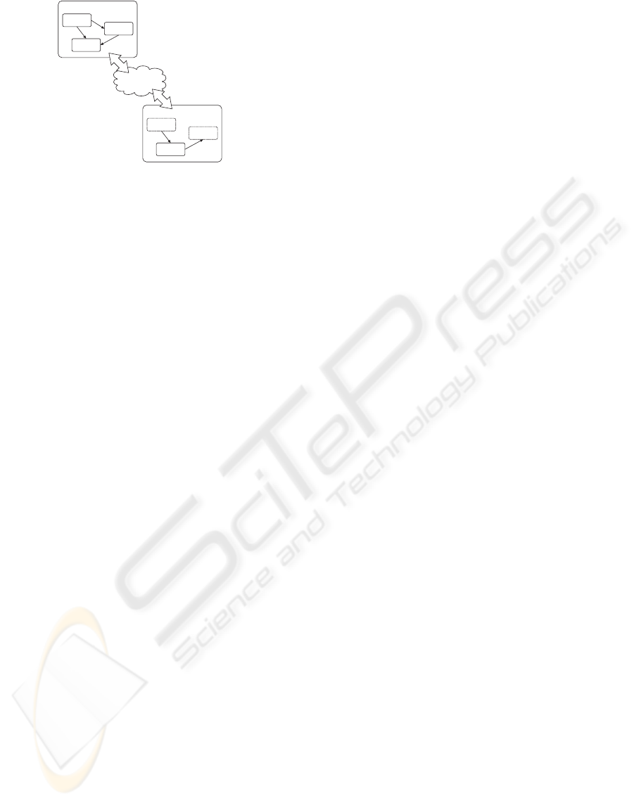
Figure 1: Network transparency by creating proxy nodes.
3.4 Namespaces
An interesting feature is the possibility to create
hierarchies of data flow graphs by using so-called
“Namespaces”. Namespaces can be integrated into
data flow graphs just like Nodes. They contain a com-
plete data flow graph consisting of Nodes and Routes.
The developer can export any inslot and outslot from
the graph contained in the Namespace to the graph
that contains the Namespace. This allows application
developers to structure their data flow graphs, hide
implementation details, and create macros that pro-
vide functionality to other developers.
3.5 Network Transparency
The concept of a data flow graph makes it simple to
introduce network transparency into the device man-
agement system. Nodes of the graph communicate
via edges, so the most elegant solution is to allow
edges to be created between nodes on different ma-
chines.
Our system does not support network transparency
directly. Instead, it is made available by a special node
called “Network”. We did this to achieve a clear sep-
aration between the device management and the net-
work code.
When the Network node starts operation, it auto-
matically connects to all other Network nodes on the
network. We are using a technique called “Multicast
DNS” (ZZMDNS, ) to automatically discover all Net-
work nodes available on the network without the need
of any configuration or central servers. After con-
necting, the Network nodes create local proxy nodes
for all nodes available on remote machines. These
proxy nodes can be used to create edges between
nodes on different machines. Figure 1 for example
shows two data flow graphs running on different ma-
chines. Nodes A and B of the first graph are available
as proxy nodes in the second graph. They can be used
in the second graph just the same way as local nodes,
but any events sent between the proxy nodes and lo-
cal nodes of the second scene graph are automatically
transferred via the network.
Each data value that gets transferred via a network
connection needs to be transformed into a system-
independent byte stream (serialization). For each data
type, a corresponding codec has to be implemented
that performs this serialization. Such codecs already
exist for the default data types provided by the sys-
tem, but the application programmer has to imple-
ment and register codecs for all application-specific
data types. Most codecs simply write the data values
into the byte stream, but more sophisticated codecs
are possible that compress the transferred data, e.g.
when transferring video frames.
3.6 Configuration File
The structure of the data flow graph is usually not hard
coded into the application. Instead, we use a configu-
ration file to store the whole data flow graph on hard
disk and to restore the graph when starting the appli-
cation again.
The format of the configuration file is XML due to
the fact that this is a well-known, established standard
for storing information. There are numerous parsers,
editors and other free tools available.
Even though it is possible to create these XML files
by hand, this approach is not recommended. Instead,
the application developer uses the integrated user in-
terface of the device management system to create a
data flow graph that fulfills his needs. This user in-
terface also allows to save the current status into a
configuration file.
There are three ways to restore a saved graph from
a configuration file:
1. The user simply loads the configuration by using
the integrated user interface.
2. The configuration is loaded when starting the ap-
plication.
3. There is a special “Inline” node that allows to in-
tegrate configuration files into other configuration
files, exactly the same way as the VRML “Inline”
node allows to integrate several VRML subgraphs
into one scene graph, or the C “include” preproces-
sor statement allows to integrate several pieces of
source code into one file.
3.7 User Interface
Our device management system has an integrated
Graphical User Interface (GUI) that allows to mod-
ify the data flow graph during runtime. During our
work on several MR projects it soon became obvious
that it is quite often impossible to do development and
SYSTEM ARCHITECTURE OF A MIXED REALITY FRAMEWORK
203

debugging directly on the machine the application is
running on. Instead, we need means to control our
application from other machines in the network.
For example, consider the development of a mobile
AR system. Such wearable systems usually do not
have conventional input devices like keyboards and
mice. This means that the user of such a system is
not able to operate user interfaces that consist of win-
dows, buttons, sliders etc. Furthermore, these appli-
cations usually run in full-screen mode which makes
it difficult to watch any debug output in console win-
dows.
Our solution is a small web server that provides
a user interface build from HTML pages. This web
server is not part of the device management system,
instead it is implemented as a node that can be added
to the data flow graph. The web server solution allows
us to control the device management system from any
device that has a simple web browser installed and
that is connected via network to the machine the ap-
plication is running on. The interface allows to in-
spect the current state of the system, to add and to
remove nodes and routes from the graph, to change
parameters, and to save the current state to or to re-
store it from a configuration file.
4 INTEGRATION IN VRML/X3D
The integration of our device management system
into VRML is straightforward. For each field data
type available in VRML, we defined a sensor node.
These sensors are defined as follows (“x” is just a
placeholder for the concrete VRML field types SF-
Bool, SFFloat, ...,MFBool, MFFloat, ...):
xSensor {
SFString [] label ""
SFBool [] out FALSE
x [in,out] value
}
For example, the sensor for boolean events is defined
as
SFBoolSensor {
SFString [] label ""
SFBool [] out FALSE
SFBool [in,out] value FALSE
}
For each sensor in the VRML file we create a corre-
sponding outslot or inslot in the graph of the device
management system (if it is an outslot or an inslot de-
pends on the value of the “out” field). The slot gets
the name specified in the “label” field. The VRML
scene sends data to outslots or receives values from
inslots via the “value” field.
For more information about the design rationales of
the sensor nodes, see (Behr et al., 2004).
5 PERFORMANCE
CONSIDERATIONS
Applications written in scripting and markup lan-
guages often suffer from the prejudice that they are
inefficient. This is not generally true. In our system,
we do not use scripting and markup languages to han-
dle time-consuming tasks like video tracking and ren-
dering – instead, they are only used to set up the struc-
ture of the system. Video tracking and rendering are
implemented in an efficient compiled language (C++)
– only the interconnection between the software mod-
ules (nodes) and the application logic is controlled by
scripts. The communication between the modules of
course introduces some overhead – but this overhead
is small compared to the calculation time needed by
tracking and rendering. Furthermore, the overhead is
compareable to the overhead of conventional frame-
works.
6 APPLICATIONS
The proposed architecture simplifies and speeds up
the development of new Mixed Reality applications.
A prefabricated pool of nodes interfacing various de-
vices allows the developer to choose the appropriate
devices for the desired application.
6.1 AR Application Using
Marker-based Tracking
This section focusses at the development of an Aug-
mented Reality application using a marker-based
video tracking system based on the well known AR-
ToolKit (Kato and Billinghurst, 1999). A common
task in Augmented Reality applications is to enhance
the view to a real scene with virtual objects contain-
ing specific information about real objects. We chose
a technical scenario, where the augmented view on a
networks witch device explains the allocation its con-
nectors, which are known from a database,and infor-
mation on how to establish a defined cable connec-
tion..
Detailed instructions can be used to augment the
users view, e.g. allowing the user a plug a cable
to the correct connector of a network device, see
figures 4 and 3 .
6.1.1 Hardware Setup
The hardware components for the user are a laptop, a
standard USB video camera for the observation of the
real scene and a (Sony LDI-100) high resolution head
mounted display for the observation of the augmented
GRAPP 2006 - COMPUTER GRAPHICS THEORY AND APPLICATIONS
204

Figure 2: User with head mounted display.
scene, see figure 2. Three buttons are mounted on the
hand-held display to enable simple user interactions
like switching application modes or adjusting para-
meters.
Figure 3: Augmented view, showing location of a connec-
tor.
6.1.2 Rendering System
Rendering is done with the Avalon(Behr et al., 2004)
rendering framework which utilizes VRML/X3D.
The described device management system is inte-
grated, data can be received via VRML sensor nodes.
One system-specific extension we use is the Viewfrus-
tum node which allows to use a projection matrix
which is calculated by the external tracking node. The
augmented environment, by means of virtual objects
to be included in the augmented view for the user
is defined in the scene-graph. The system is imple-
mented as a video-see through, so video images are
drawn as background to the application window. The
scene-graph includes a Transform node and additional
child nodes representing the corresponding virtual ob-
ject for each marker. The Viewfrustum, the Transform
node and the Switch node are updated according to
corresponding sensor nodes.
Figure 4: Augmented view, showing additional information
how to plug in a connector.
6.1.3 Software Components and Data Flow
To implement the mentioned AR application, we are
able to select prepared modules, represented as nodes
which can be inserted into our data flow graph. The
video tracking system consists of a video source, the
computer vision algorithms and optional filters that
allow e.g. grouping of several markers. The nodes we
use are described briefly in the following. The appli-
cation can be implemented by setting up a data flow
graph holding the corresponding nodes and routes
connecting corresponding inslots and outslots, see
figure 5 for a sample configuration file. When the ap-
plication starts, the nodes and routes are created, and
the system is ready for use. The integrated web inter-
face shows all nodes and routes that have been created
and allows to examine their state, sources of error can
easily be determined and eliminated. For example if
there is no camera connected to the system, the video
node will fail to initialize resulting in a blank applica-
tion screen. The web interface allows a look inside the
system and shows the existing nodes and their current
state.
6.1.4 Video Node
The video node produces video data by interfacing
the camera and, if necessary, converting compressed
video formats to a suitable uncompressed format for
the vision algorithms and the display system. Each
frame of the video sequence is pushed through an
SFImage outslot as a single image. Optional para-
meters allow to specify image size or image format to
initialize the video node in a suitable way.
6.1.5 Video Tracking Node
The video tracking node provides the tracking algo-
rithm to compute the transformation of each recog-
nized marker in the video image. Video frames are re-
SYSTEM ARCHITECTURE OF A MIXED REALITY FRAMEWORK
205

<?xml version="1.0"?>
<HID versionMajor="1" versionMinor="0">
<Route from="video/frames" to="ARToolkit/frames_in"/>
<Route from="ARToolkit/frames_out" to="frame"/>
<Route from="ARToolkit/projection_matrix" to="projection"/>
<Route from="ARToolkit/m1" to="MarkerGroup/m1"/>
<Route from="ARToolkit/m1_select" to="MarkerGroup/m1_select"/>
<Route from="ARToolkit/m2" to="MarkerGroup/m2"/>
<Route from="ARToolkit/m2_select" to="MarkerGroup/m2_select"/>
<Route from="MarkerGroup/group" to="model_transform"/>
<Route from="MarkerGroup/group_select" to="model_select"/>
<Node type="Video" label="Video">
<Parameter name="Width" value="640"/>
<Parameter name="Height" value="480"/>
<Parameter name="Format" value="RGB24"/>
<ExternalRoute internal="
*
" external="{NamespaceLabel}/{SlotLabel}"/>
</Node>
<Node type="ARToolkit" label="ARToolkit">
<Parameter name="camera_param" value="http://pc978/philips.dat"/>
<Parameter name="far" value="5000"/>
<Parameter name="near"value="50"/>
<Parameter name="threshold" value="100"/>
<Parameter name="quality" value="0.7"/>
<Parameter name="markers" value="m1,http://pc978/markers/m1.patt,15;
m2,http://pc978/markers/m2.patt,15;/>
<ExternalRoute internal="
*
" external="{NamespaceLabel}/{SlotLabel}"/>
</Node>
<Node type="Group" label="MarkerGroup">
<Parameter name="name" value="group"/>
<Parameter name="mode" value="linear"/>
<Parameter name="markers" value="m1,0 0 0,0 0 0 1;
m2,122 -404.5 0,0001;"/>
<ExternalRoute internal="
*
" external="{SlotLabel}"/>
</Node>
<Node type="Network" label="Network">
<Parameter name="ID" value="3002"/>
<ExternalRoute internal="
*
" external="{SlotLabel}"/>
</Node>
<Node type="Web" label="Web">
</Node>
</HID>
Figure 5: XML configuration file for the device manage-
ment.
ceived through an SFImage inslot and processed with
computer vision algorithms, which allow to recognize
trained patterns. The Tracking Node has to be initial-
ized with a number of pattern descriptions. This is
done by supplying a parameter string containing the
pattern name and the URL of the corresponding pat-
tern definition files, and the pattern size for each used
marker. Other parameter is the URL of the camera
calibration file, the near and far values for the view
frustum and the image segmentation threshold. The
files are retrieved and the module creates the out-
slots for each pattern. The rendering system needs
to be supplied with the transformation of the recog-
nized patterns to update the corresponding Transform
nodes in its scene-graph. To toggle the visibility of
the corresponding object, the information weather it
has been detected or not is also provided. A sam-
ple VRML file is shown in figure 6. Two outslots are
created for each pattern, one outslot of type SFMa-
trix, and another outslot of type SFBool. All marker
transformations are calculated for the camera model
defined by the camera calibration file and additional
near and far plane parameters. The corresponding
projection matrix for the rendering system is supplied
through an additional outslot of type SFMatrix. The
vision algorithms are time-consuming, to avoid dis-
placed augmentations the processed video frames are
forwarded through an SFImage outslot at the same
time the marker information is passed though the cor-
responding outslots.
#VRML V2.0 utf8
DEF matrixCam Viewfrustum{
zNear 50.0
zFar 5000.0
}
DEF projectionSensor SFMatrixSensor {
label "ArToolKit/projection"
description "Projection Sensor"
}
ROUTE projectionSensor.value_changed TO matrixCam.set_projection
DEF imageBG ImageBackground {
texture DEF image PixelTexture {}
}
DEF imageSensor SFImageSensor {
label "ARToolKit/frames_out"
description "Image Sensor"
}
ROUTE imageSensor.value_changed TO image.set_image
DEF model_trans MatrixTransform {
children [
DEF inlineNode Inline {
url"http://pc990/augmentation.wrl"
}
]
}
DEF modelSensor SFMatrixSensor {
label "model_transform"
description "Model transform Sensor"
}
DEF modelSelectSensor BoolSensor {
label "model_select"
description "Model select Sensor"
}
ROUTE modelSensor.value_changed TO model_trans.set_matrix
ROUTE modelSelectSensor.value_changed TO model_trans.set_visible
DEF urlSensor SFStringSensor {
label "augmentation_url"
description "augmentation url Sensor"
}
ROUTE urlSensor.value_changed TO inlineNode.set_url
Figure 6: VRML file for the rendering system.
6.1.6 Group Node
Tracking with single markers does often not satisfy
the needs of the application, because some markers
get occluded or unrecognizable when the camera is
moved. The use of redundant markers is possible if
the displacement in between is known and remains
fix during runtime. A group node provides inslots
for each pattern and calculates the group transforma-
tion by applying appropriate offset transformations to
the pattern transformations, which is mapping each
marker transformation to a group transformation. The
in slots and corresponding offset transformations have
to be provided as parameters, see figure 5 for exam-
ple. The group transformations for each pattern are
then combined by applying a linear combination of
transformations as introduced in (Alexa, 2002). The
group transformation is then provided at the outslot of
the group-node.
6.2 Extending the Application
The application above has been enhanced to allow a
simple communication between user and an ’remote’
expert at a different location. The expert is supplied
with the camera images of the distant user, and is able
to move a pointer and place additional virtual objects
and into the view of the worker. Furthermore a bidi-
rectional speech communication is necessary to ex-
tend the information interchange.
GRAPP 2006 - COMPUTER GRAPHICS THEORY AND APPLICATIONS
206

The expert requires a workstation with network con-
nection, sound hardware and a headset. Interactions
are done by mouse and keyboard. The user of the
AR system has the equipment mentioned above plus
a headset and network connection.
Two nodes at each system enable sound recording and
playback. The sound-record node accesses the digi-
tizer of the installed sound hardware, and provides the
PCM data on an outslot of type SFSample. The num-
ber of bits to sample, sample rate etc. are optional
parameters, which can be provided for initialization.
The counterpart is the sound-play node, which re-
ceives the samples using an inslot of type SFSam-
ple and passes the sample values to the digital/analog
converter of the sound hardware.
The Network transparency of the system allows to es-
tablish routes between inslots and outslots on differ-
ent machines. Video image and tracking information
are routed to the rendering system of the remote ex-
pert, which has the same scene-graph loaded. Mouse
interactions are grabbed by the mouse node and pro-
vided on an outslot of type SFVec2f. The user of
the AR system has an overlay which is shifted on
the screen according to the mouse movements of the
remote expert. The geometry of the overlay can be
modified by the remote expert by changing the URL
field of an Inline node in the scene graph of the AR-
System. The URL needs to be specified by the remote
expert, the corresponding string is transferred via an
SFString outslot at the expert system and an inslot in
the rendering system of the user.
7 CONCLUSION
In this paper we presented the framework we use for
the development of our MR applications. It is cur-
rently available on several operating systems (Win-
dows, MacOS X, Linux, IRIX and SunOS) and as
a Java package (written in pure Java, therefore run-
ning on all systems providing a Java virtual machine).
The experiences we gain from the practical use of the
advance the further development of the system. Our
current research focus is the identification, design and
implementation of new nodes that further ease the de-
velopment of MR applications.
REFERENCES
Alexa, M. (2002). Linear Combination of Transformations.
In Proceedings of ACM SIGGRAPH 2002, pages 380–
386.
Arsenault, L. E. and Kelso, J. (2002). The DIVERSE
Toolkit: A Toolkit for Distributed Simulations and Pe-
ripheral Device Services. In VR 2002.
Bauer, M., Bruegge, B., Klinker, G., MacWilliams, A.,
Reicher, T., Riss, S., Sandor, C., and Wagner, M.
(2001). Design of a component-based augmented re-
ality framework. In Proceedings of ISAR 2001.
Behr, J., D
¨
ahne, P., and Roth, M. (2004). Utilizing X3D for
Immersive Environments. In Proceedings of Web3D
2004, pages 71–78.
Cruz-Neira, C., Bierbaum, A., Hartling, P., Just, C., and
Meinert, K. (2002). VR Juggler - An Open Source
Platform for Virtual Reality Applications. In Procs of
40th AIAA Aerospace Sciences Meeting and Exhibit
’02.
Fr
¨
ohlich, T. and Roth, M. (2000). Integration of Multi-
dimensional Interaction Devices in Real-Time Com-
puter Graphics Applications. In Computer Graphics
Forum 19, pages C–313 – C–319.
Kato, H. and Billinghurst, M. (1999). Marker tracking and
HMD calibration for a video-based augmented reality
conferencing system. In 2nd IEEE and ACM Interna-
tional Workshop on Augmented Reality, pages 85–94.
MacIntyre, B. and Feiner, S. (1996). Language-level sup-
port for exploratory programming of distributed vir-
tual environments. In Proceedings of UIST ’96, pages
83 – 95.
Owen, C., Tang, A., and Xiao, F. (2003). ImageTclAR:
A Blended Script and Compiled Code Development
System for Augmented Reality. In Proceedings of the
International Workshop on Software Technology for
Augmented Reality Systems.
Piekarski, W. and Thomas, B. H. (2003). An object-oriented
software architecture for 3D mixed reality applica-
tions. In Proceedings of ISMAR 2003.
Reitmayr, G. and Schmalstieg, D. (2001). An Open Soft-
ware Architecture for Virtual Reality Interaction. In
Proceedings of VRST 2001.
Schmalstieg, D., Fuhrmann, A., Hesina, G., Szalavari, Z.,
Encarnac¸
˜
ao, L. M., Gervautz, M., and Purgathofer, W.
(2002). The Studierstube Augmented Reality Project.
Presence, 11.
Taylor, R. M., Hudson, T. C., Seeger, A., Weber, H.,
Juliano, J., and Helser, A. T. (2001). VRPN: A
Device-Independent, Network-Transparent VR Pe-
ripheral System. In Proceedings of VRST 2001.
ZZMDNS. Multicast DNS, IETF draft.
http://www.multicastdns.org/.
SYSTEM ARCHITECTURE OF A MIXED REALITY FRAMEWORK
207
