LAG CAMERA: A MOVING MULTI-CAMERA ARRAY
FOR SCENE ACQUISITION
Daniel G. Aliaga, Yi Xu and Voicu Popescu
Department of Computer Science at Purdue University
West Lafayette, IN – USA
Keywords: computer graphics, space-time stereo, lightfields, lumigraphs, foreground object removal, camera clusters.
Abstract: Many applications, such as telepresence, virtual reality, and interactive walkthroughs, require a three-
dimensional (3D) model of real-world environments. Methods, such as lightfields, geometric reconstruction
and computer vision use cameras to acquire visual samples of the environment and construct a model.
Unfortunately, obtaining models of real-world locations is a challenging task. In particular, important
environments are often actively in use, containing moving objects, such as people entering and leaving the
scene. The methods previously listed have difficulty in capturing the color and structure of the environment
while in the presence of moving and temporary occluders. We describeF a class of cameras called lag
cameras. The main concept is to generalize a camera to take samples over space and time. Such a camera,
can easily and interactively detect moving objects while continuously moving through the environment.
Moreover, since both the lag camera and occluder are moving, the scene behind the occluder is captured by
the lag camera even from viewpoints where the occluder lies in between the lag camera and the hidden
scene. We demonstrate an implementation of a lag camera, complete with analysis and captured
environments.
1 INTRODUCTION
Computer graphics applications such as
telepresence, virtual reality, and interactive
walkthroughs require a three-dimensional (3D)
model of real-world environments. Students can
“visit” famous historical sites, such as museums,
temples, battlefields, and distant cities; archeologists
can capture excavation sites as they evolve over
time; soldiers and fire fighters can train in simulated
environments; real estate agents can show potential
buyers interiors of homes for sale via the Internet;
and, people world-wide can enjoy virtual travel and
3D games. Thus, a growing desire exists for
methods which can efficiently capture important and
visually stunning environments.
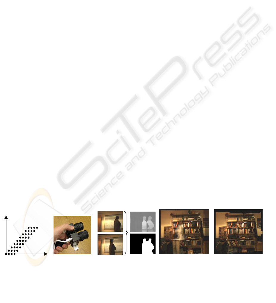
Figure 1: Lag Camera. (a) The general n-view lag camera samples a scene over space and time by ensuring at least one
camera “lags” behind (n=4 in figure). (b) A snapshot of our prototype 2-view lag camera. (c) Using images acquired from
the same viewpoint but at two instances in time, we can easily identify foreground motion as well as acquire samples of
the background in the presence of moving occluders. This allows us to capture busy, in-use environment despite temporary
occluders appearing and disappearing from the images. Rendering results without (d) and with (e) our method are shown.
(b) (a)
space
time
n-view lag
camera
(c) (e)
(d)
98
G. Aliaga D., Xu Y. and Popescu V. (2006).
LAG CAMERA: A MOVING MULTI-CAMERA ARRAY FOR SCENE ACQUISITION.
In Proceedings of the First International Conference on Computer Graphics Theory and Applications, pages 98-107
DOI: 10.5220/0001356300980107
Copyright
c
SciTePress

Numerous methods, such as lightfield acquisition
and geometric reconstruction, use cameras to
acquire visual samples of the environment and
construct a model. Unfortunately, efficiently
obtaining models of complex real-world locations is
a challenging task. In particular, the aforementioned
important environments are often actively in use,
containing moving objects, such as people entering
and leaving the scene. The methods listed have
difficulty in capturing the color and structure of the
environment while in the presence of moving and
temporary occluders. An efficient acquisition
process must be able to proceed even in such
situations.
Our key idea is to generalize the concept of a
camera to take samples over space and time. Such a
camera can easily and interactively detect and
sample moving objects while continuously moving
through the environment. Furthermore, the camera is
able to acquire images of the (hidden) scene
regardless of the occlusions produced by moving
obstacles. This reduces capture time by avoiding
having to revisit temporarily occluded surfaces. For
example, acquisition can use a hand-held version of
our camera design to acquire a lightfield of a large
statue even if people are walking in the field-of-
view of the camera and between the camera and the
statue (as would often occur for an important
structure on display). Our camera system can be
mounted on a car and used to acquire images of the
architectural structures of an urban neighborhood
even in the presence of other moving cars and
people. Our camera can be used to simultaneously
move within and capture images of a large museum
even during normal operation hours when the
museum is full of visitors. Since acquisition of a
large environment requires significant time, it is
unrealistic to ask site supervisors to close-down a
location for a lengthy capture session. However,
visually stunning, important, and thus actively-used
sites are precisely the ones we are interested in
capturing.
In this paper, we introduce a class of cameras
called lag cameras. The main concept is to have a
small cluster of cameras where at least one camera
follows (or “lags”) behind a lead camera and to
interactively acquire space-time samples of the
environment. In particular, follow cameras capture
the scene from approximately the same viewpoints
as lead cameras but at later instances in time. A lag
camera supports and assists various space-time
processing methods including space-time stereo,
foreground object processing, environment
reconstruction, and lumigraphs and lightfields.
Figure 1a illustrates a space-time sampling of an
environment using a general n-view lag camera. The
horizontal axis corresponds to samples taken over
3D space. The vertical axis corresponds to samples
taken over time. As the cameras move, the lead
camera (rightmost camera in Figure 1a) moves to a
new viewpoint and all other cameras follow and
capture views of the environment from previously
visited viewpoints but at later instances in time.
Figure 1b shows a picture of our first
implementation of a lag camera using only two
cameras. Figure 1c shows example images captured
by our lag camera. These images are acquired from
approximately the same viewpoint and at nearby
instances in time. Hence, a lag camera can move
through the environment, efficiently capturing
image samples, yet easily and interactively detecting
moving foreground objects. Moreover, since both
the occluder and the lag camera are moving, the
system can both omit foreground objects and obtain
samples of surfaces behind the occluder. Figure 1e
shows an example application of lag cameras to
produce novel views using a modified unstructured
lumigraph. Figure 1d shows a naïve reconstruction
from the same viewpoint with a moving occluder
partially appearing.
Our main contributions are as follows:
• We describe lag cameras that can move through
an environment while acquiring space-time
samples of the scene.
• We develop a new motion detection algorithm
using a lag camera to create motion masks. This
technique allows us to easily and interactively
detect moving objects in the scene while the
camera itself is undergoing motion. The
detected moving objects can then be extracted,
reconstructed or removed from the capture.
• We provide a method for acquiring samples of a
static background scene even in the presence of
moving occluders in between the camera and
the scene. This allows us to acquire images of
in-use environments even if people enter and
leave the field of view of the camera.
2 RELATED WORK
Our lag camera design borrows ideas from multiple
areas of research. Previous methods have used
camera clusters to increase field of view or construct
LAG CAMERA: A MOVING MULTI-CAMERA ARRAY FOR SCENE ACQUISITION
99

stereo rigs. In contrast, the purpose of a lag camera,
while also a cluster of cameras, is to acquire space-
time samples for foreground and background
sampling.
Space-time sampling addresses the 3D
reconstruction problem by sampling in both spatial
and temporal domains. For example, Davis et al
(Davis, 2005) use a spatial-temporal algorithm to
reconstruct depth for moving scenes. Similar work
can also be found in (Zhang, 2003). Our method is
related to these approaches in the sense of
supporting such space-time algorithms. Instead of
using regular cameras, we propose a novel camera
design that is well-suited for space-time processing.
Lightfield and lumigraph rendering methods
capture and represent the scene with a group of
images (Levoy, 1996; Gortler, 1996; Buehler 2001).
Rays are selected and blended from the reference
images to create novel views of the scene without
explicit knowledge of the geometry of the scene.
Standard lightfield and lumigraph methods are
restricted to static scenes and thus to the space
domain. There exist methods that attempt to capture
and render dynamic scenes using lightfield and
lumigraph rendering (Naemura 2002; Yang, 2002;
Matusik, 2004). These methods treat images
captured at each time instance as an independent
lightfield. Hence, no temporal coherence
information is exploited in these methods. Space-
time lightfield rendering (Wang, 2005a)interpolates
the reference views in both temporal and spatial
domain using an array of static cameras. After
establishing feature correspondence among
successive frames for each camera, new images are
synthesized in the temporal domain using a novel
edge-guided image morphing algorithm. Then these
synthesized images are used to interpolate the final
rendering result spatially. Our method, on the other
hand, acquires spatial and temporal samples using a
moving cluster of cameras and with real-time
algorithms.
Our method is also related to algorithms for
foreground object cutout. Interactive video cutout
allows users to cut foreground objects from video
sequences (Wang, 2005b). They use a volumetric
painting interface to manually select rough
approximations of foreground objects and use a
computationally-expensive hierarchical
segmentation algorithm to refine the selection of
foreground objects. Afterwards, a spatial-temporal
alpha matting method is used to composite objects
onto new background. A similar work is presented
in (Li, 2005). Our method is designed to
automatically and interactively detect moving
foreground objects for a moving camera – a
particularly difficult case.
Finally, our work is also related to video textures
(Schödl, 2000) and panoramic video textures
(Agarwala, 2005). A video texture uses a sampling
of a scene over time but from a static viewpoint. The
captured images are re-arranged into a seemingly
infinite and continuous video of periodic motion in
the scene. A panoramic video texture acquires
images over time and with a camera rotating in
place. Using dynamic programming and a
hierarchical min-cut optimization algorithm, the
method stitches subsets of the captured imagery
together producing an apparent large field-of-view
continuous video of periodic motions in the
surrounding environment. In contrast, our technique
is able to capture more than one temporal sample
from each viewpoint as the lag camera moves (in
3D) within the scene. Our spatial and temporal
sampling strategy allows us to implement methods
for easily detecting moving objects (focusing on
either reconstructing the static background or the
moving objects), capturing samples of surfaces
temporarily occluded, and improving acquisition
efficiency by allowing the camera to continuously
move and capture in-use environments.
3 DESIGNING A LAG CAMERA
3.1 Camera Configurations
There are many possible configurations for a general
n-view lag camera. The designs must take into
account the expected type of camera motion and
scene motion. In particular, for cameras there are
four cases: (1) static camera and static scene, (2)
static camera and moving scene, (3) moving camera
and static scene, and (4) moving camera and moving
scene. A lag camera essentially maps the most
difficult case (moving camera and moving scene) to
the case of a static camera and a moving scene and
enables the use of all algorithms for static cameras.
Thus, the design focuses on making a moving
camera act like a static camera for at least a small
time interval.
GRAPP 2006 - COMPUTER GRAPHICS THEORY AND APPLICATIONS
100
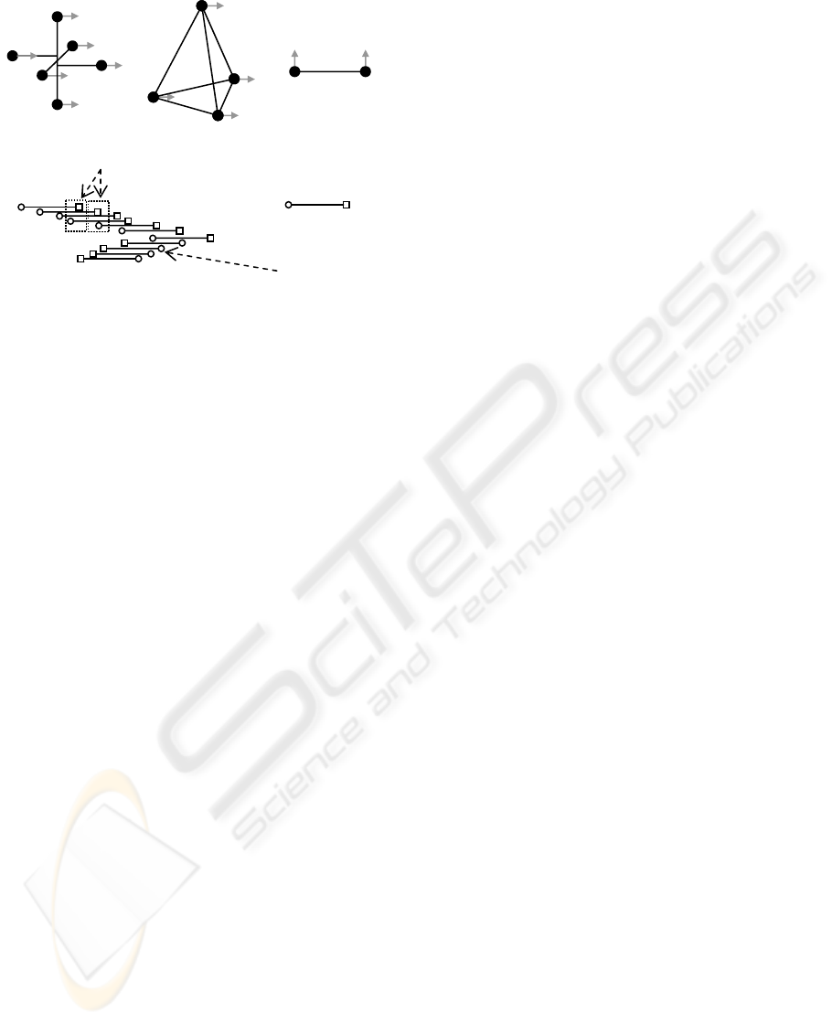
Figure 2 demonstrates camera arrangements for
several camera motions. Each design must be
accurately manufactured or calibrated in software.
Figure 2a provides a design for follow cameras that
precisely lag behind lead cameras for all motions
parallel to either x- or y-axis and approximately lags
behind for motion parallel to the z-axis. Figure 2b
depicts a configuration with less cameras that
provides approximate follow and lead cameras for
any movement direction. By placing cameras on the
corners of a regular tetrahedron, follow cameras will
almost trace the path of lead cameras. Figure 2c
shows a single-axis lag camera for motion along a
single axis. This is the design we implemented for
the experiments in this paper. It lets the user move
the camera along any straight line in 3D space; but,
the user must keep the baseline of the camera-pair
approximately parallel to the movement direction.
The velocity vector of the lag camera can be used to
easily determine the lead camera and when the
cameras are not moving in a direction parallel to the
baseline. We found this to be a simple and intuitive
motion to perform with a portable camera (Figure
2d).
Although Figure 2c illustrates a design using two
cameras, the miniaturization of technology makes it
easy to extend the configuration to more cameras
packed tightly together. In fact, a shorter baseline
between cameras of the lag camera cluster and the
higher frame rates of future technology actually
improves the performance of the lag camera by
enabling a larger ratio between object velocity and
camera velocity. Nevertheless, the system would
have to store more images and support higher
bandwidths to maintain interactivity.
3.2 Lag Camera Image Pairs
Given a lag camera configuration, we attempt to pair
a follow camera image with the closest and
previously obtained lead camera image from ideally
the same viewpoint. The lead camera image paired
to a follow camera image for this purpose is not
necessarily from exactly one previous frame-time
ago (Figure 2d, Figure 3). Rather, the pairing of lead
camera and follow camera images depends on the
camera motion. Moreover, because of discrete frame
rates, the optical axis of the cameras not being
exactly parallel to each other, and the freedom of
handheld motions, the follow camera will not fall
exactly on the viewpoint and view direction of the
lead camera (in practice, it is off by only a few
millimeters).
To address this, we warp the lead camera image
to the follow camera viewpoint. As a preprocess, we
obtain the internal and relative external parameters
of each camera using calibration techniques. Then,
using a simple proxy of the environment, we warp
the lead camera image to the follow camera
viewpoint. We do not require dense depth
information or have to compute depth on the fly.
Rather, the proxy provides very approximate
information but that is sufficient to align the images
in the pair. They are typically handmade and consist
of a few planes or a box. To compensate for
remaining inaccuracies, we further align the two
images by morphing one image to the other using a
sparse set of automatically tracked and corresponded
point features between the two images.
4 FOREGROUND OBJECTS
4.1 Motion Masks
As the lag camera moves through the environment,
it is able to detect (sample) foreground motion by
simply comparing a follow camera image to its
Figure 2: Lag Camera Configurations. There are many
p
ossible lag camera configurations. For instance, (a) a
six camera design (each filled dot represents a camera),
(b) a four camera design, and (c) a two camera design
which provides a follow and lead camera only for
camera motion parallel to the baseline. A user simply
zigzags this lag camera from one side to another or
moves the camera along a smooth continuous path. (d)
This figure shows a top view of a capturing path. For
each follow camera, the closest lead camera is found.
no nearb
y
lead
lea
d
follow
(d
)
p
airs
(a) (b) (c)
LAG CAMERA: A MOVING MULTI-CAMERA ARRAY FOR SCENE ACQUISITION
101
paired lead camera image. Then, a moving object
can be explicitly captured or intentionally removed
from the images. The simplest method for
identifying object motion in captured imagery is to
create a motion mask (Figure 3). Although we could
produce different masks for each camera, for
simplicity we produce a single mask for both
images. The mask indicates which subset of the lead
camera and follow camera image can be used, for
instance, in lumigraph rendering, feature tracking, or
3D reconstruction.
To create the mask, the system generates on-the-
fly thresholded difference images. After warping the
lead camera image to the follow camera viewpoint,
the images are smoothed using a Gaussian blur and
subtracted from each other to produce a difference
image. The absolute value difference image is
thresholded to produce a binary image which is then
subject to an image processing “close” operator to
join nearby image components. The contours of all
blobs are found and filled (small contours are
considered noise and removed). Since warping the
lead camera image to the follow camera viewpoint
does not produce exactly overlapping images, a thin
image border is excluded during processing.
Objects which temporarily stop in the scene can
still be detected and an appropriate object mask
created. When a moving object stops, its difference
image becomes zero. However, a motion exists
before (and after) the stop. Thus, a sudden
disappearance (or appearance) of a contour signals a
temporarily stationary object. We can re-project the
masks of the frames immediately preceding and
succeeding the stop frames to the frame where the
difference image goes to zero. Once an object stops
for too long, we can optionally choose to call it
background.
Multiple objects in the scene can also move
and/or stop. To support this situation, we compose
masks together. A mask is composed of a
combination of masks for moving objects and re-
projections of masks for temporarily stationary
objects. Figures 7 and 8 (in the results section)
demonstrate this functionality.
4.2 Object Displacement
Given a lag camera design, we can use rough
estimates of typical object distances and velocities
(e.g., assume the camera is handheld, assume the
scene contains walking humans, etc) to better
understand the motion masks and to estimate the
sensitivity of the lag camera to the motions. More
precisely, the image-space displacement of an object
from a follow camera image to its warped lead
camera image causes a double image of the moving
object to appear in the difference image. The double
image may either partially overlap or be completely
disjoint. In either case, the displacement between
object centers is called x. The displacement direction
corresponds to the projection of the object velocity
onto the image plane of the lag camera.
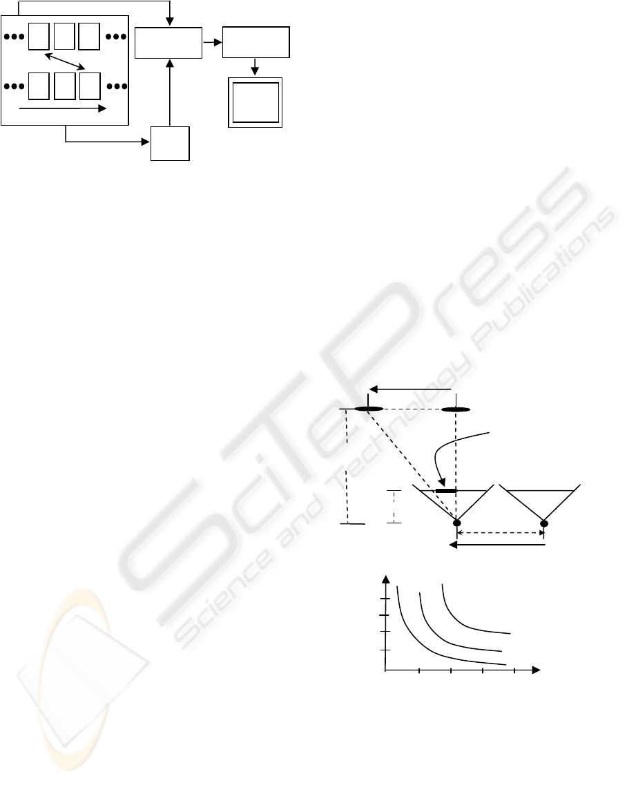
Figure 3: Computing Motion Masks. Each follow frame
F is paired with a lead frame L. L is warped to the
viewpoint of F. A difference image of frame F and
Warp(L) is computed. The motion mask is generated by
thresholding the difference image.
Warp
Difference
Threshold
Mask
F
F
F
L L L
time
Figure 4: Object Displacement. (a) Given the baseline b,
focal length f, depth of the scene d, the camera velocity c
v
and object velocity o
v
, we can estimate the object
displacement x on the two frames. (b) graphs x as a
function of d for various R values.
R=1
O
v
b
C
v
C
f
Cl
h
d
x
(
a
)
f
1 2 3 4
R=
2
x
d
R=
3
(
b
)
2
1
4
3
GRAPP 2006 - COMPUTER GRAPHICS THEORY AND APPLICATIONS
102
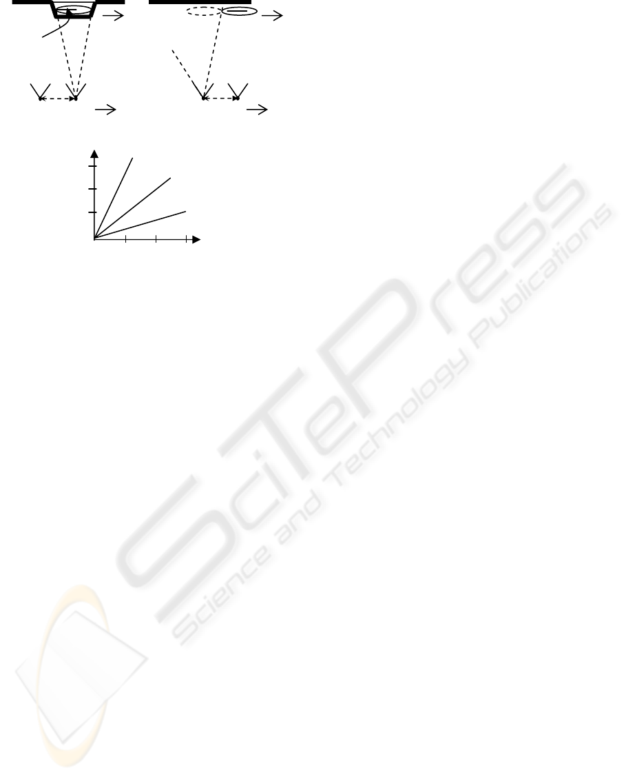
Figure 4a contains a diagram of a lag-camera
viewing a moving object. The lead camera c
l
is
separated from the follow camera c
f
by a baseline b.
The velocity of both cameras is c
v
. The object o
displaces significantly when it is moving in a
direction parallel to c
v
, such as o
v
. (In this figure
both c
v
and o
v
are in the same direction. The
discussion that follows works equally if c
v
and o
v
are
moving in opposite directions.) The distance from
the cameras to the objects is d and the focal length
of the cameras is f. Thus, the time it takes the follow
camera to reach the position of the lead camera is t
c
= b/c
v
. In this amount of time, the object has moved
by h = o
v
t
c
in world space. If we define the ratio of
the object velocity o
v
to the camera velocity c
v
to be
R and use similar triangles, this brings us to the
following simplified expression for the magnitude of
the screen-space displacement x of the object: |x| = |
(fb/d)R |.
This expression is useful to estimate how much
the object will move from follow camera image to
the corresponding warped lead camera image. For a
given lag camera, we can consider f and b to be
constants. Figure 4b shows a graph of x as a
function of d for several values of R. In this graph,
we use the focal length f (.377 cms) and baseline b
(4 cms) of our lag camera. For example, if the object
and camera move at the same relative velocity
(R=1), the object displaces 14 pixels for a scene
distance of 300 cms with image resolution at 1024
by 768 and field of view of 50 degrees.
5 BACKGROUND SAMPLING
Since both scene and camera are moving, a lag
camera captures surface samples occluded in one
camera view with samples captured by another
camera (or cameras) from approximately the same
viewpoint. This allows us to acquire the background
scene even if it is apparently hidden during capture
by moving objects. This property is especially useful
for dense image acquisition (e.g.
lightfields/lumigraphs). It allows us to acquire an
environment in less time because we do not have to
revisit a location due to occluders temporarily in
between camera and scene.
Figure 5a illustrates this property. It depicts a
scenario where the object radius r and object
velocity o
v
are such that the object appears
completely disjoint in the difference image between
corresponded lead camera and follow camera
images. In this scenario, the follow camera image of
the pair samples a surface occluded in the lead
camera image at a previous time instance. Both
images are captured from approximately the same
viewpoint. However, if the object is too large or
moving too slow, the difference image will contain
overlapping projections of the moving occluder. The
surfaces obscured by the intersection of the two
projections of the moving occluder will not be fully
sampled by either camera.
From Figure 5a, it is easy to see the projections
of the moving object in the difference image will not
overlap if the object displacement during the time
between lead camera and follow camera images is at
least equal to the object diameter, namely 2r
≤
bR.
Given a predetermined object radius r, the baseline b
for the lag camera, and objects moving amongst the
background scene, this expression tells us how fast
we can move the lag camera relative to moving
objects and still fully capture the background scene
despite the occluders. Figure 5b graphs the smallest
values for R as a function of r for several values of
b.
Figure 5: Background Sampling. (a) Part of the surface is
occluded by the object. Camera and the object are
moving to the right. (b) Follow camera is now at same
location as previous lead camera. Occluded surface can
be seen as long as the object does not overlap in volume.
(c) Graphs the minimum value of R to achieve full
sampling of background.
(
c
)
r
R
b = 4
b =
2
b = 1
1 2
3
3
2
1
b
C
C
f
C
f
r
(
a
)
b
(
b
)
LAG CAMERA: A MOVING MULTI-CAMERA ARRAY FOR SCENE ACQUISITION
103
6 IMPLEMENTATION DETAILS
Our lag camera system uses a pair of Point Grey
Research (PGR) Flea cameras rigidly attached to an
aluminum base and connected to a standard Dell PC
via a Firewire connection. The cameras capture
color images of the environment at 1024x768 pixel
resolution and at a rate of 15 Hz. Software for our
lag camera is implemented in C++ using standard
OpenGL, GLUI, GLUT, and OpenCV libraries. To
perform camera calibration, we use an adaptation of
Reg Wilson’s implementation of the standard Tsai
camera model (Tsai, 1987). Calibration indicates the
angle between the optical axis of our two cameras is
0.84 degrees and the distance between the two
cameras is 4.098 cms.
Our prototype lag camera system is attached to a
Immersion Corporation MicroScribe G2LX arm
(http://www.emicroscribe.com). This mechanically
tracked arm provides six degrees-of-freedom and a
workspace size of 66 inches. Although camera pose
can be estimated via a variety of passive methods
(e.g., feature tracking, landmark-detection, etc.) or
active methods (e.g., magnetic trackers, optical
ceiling trackers, inertial sensors, etc.), we use the
arm in this implementation so that we can focus on
developing lag camera algorithms.
6.1 Modified Unstructured
Lumigraph Renderer
To demonstrate environment reconstructions, we use
a modified unstructured lumigraph renderer (ULR)
(Buehler, 2001). A standard ULR system uses the
projection of a finely subdivided proxy to determine
a set of visible surface vertices. A set of weights is
computed for each visible surface vertex. These
weights determine the set of captured images to use
as reference images for generating a novel
lumigraph rendering of the scene. We augment the
ULR system to also consider the object motion
masks computed in Section 4. These masks
determine what subset of the reference images can
be used to reconstruct the scene. In our
implementation, we modify the weighting scheme of
a ULR system to include whether the visible surface
vertices project onto a valid or invalid region of the
reference images. If a vertex falls onto an invalid
region, the system will choose the next best
reference image until a desired number of reference
images are found for each vertex. Our current ULR
implementation runs off-line but hardware-friendly
implementations have been shown in the past
(Buehler, 2001) and our method is well suited for
these.
7 RESULTS AND DISCUSSION
We have constructed and captured several scenes
using our prototype 2-view lag camera. Table 1 lists
our captured scenes. The five capture sequences
have different combinations of scenes, motion,
stops, and number of objects. The length of the
image sequences range from 102 to 298 images. The
video accompanying this paper demonstrates the lag
camera, scenes, algorithms, and scene
reconstructions.
The lag camera captures, warps, thresholds,
creates masks, and display images at interactive
rates (about 10 Hz). We store in memory 1024x768
resolution color images from the follow and lead
cameras. The differences and masks are generated at
quarter-resolution (256x192). Image warping and
re-projection is done using OpenGL rendering and
projective texture-mapping.
Table 1: Captured Scenes. We show the names, description, and number of images for our example sequences.
Scene Description No. Images
walk Student walks into scene and walks out. 142
walk-stop-walk Student walks into scene, stops to read the board, and walks out. 102
walk-hi-walk Student walks into scene, says hi, waves, and walks out. 126
walk-head-walk Student walks into scene, appears surprised, and another guy appears, both
walk away.
146
motion in office Student tries his best to hide the background in an office scene during capture. 298
GRAPP 2006 - COMPUTER GRAPHICS THEORY AND APPLICATIONS
104
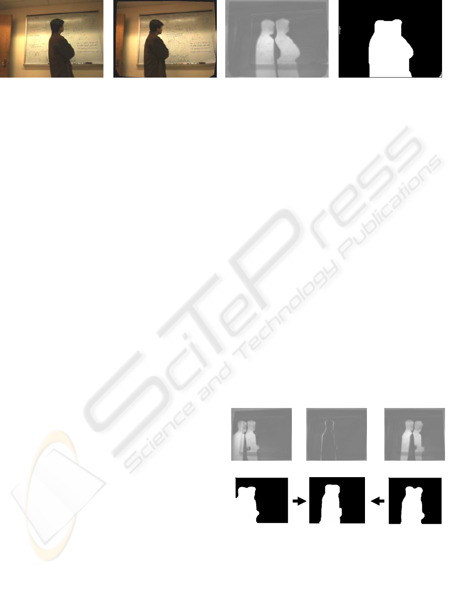
Figure 6 demonstrates the sequence of
operations for creating a motion mask. Figure 6a
shows an example image from a follow camera and
Figure 6b shows an example warped image from the
paired lead camera. The follow camera lags behind
the lead camera by 1.125 seconds and comes with
0.351 centimeters of the lead camera viewpoint
(average numbers are about the same). Figure 7c
shows the absolute value difference image
normalized to the range 128 to 255 (e.g., zero
difference maps to gray and maximal difference
maps to white). Figure 7d shows the thresholded
binary mask image resulting from the difference
image. The proxy, in this case, is a plane registered
in place with the observed wall using simple visual
approximation.
Figure 7 illustrates how motion masks are re-
projected when a moving object temporarily stops.
Figures 7(a, d) show the difference and mask images
several frames before the motion stops. Figures 7(c,
f) show the difference and mask images a few
frames after the motion resumes. When the motion
stops the difference image is zero (gray). Figure 7b
shows the difference image one frame before motion
stops (so that some of the contour is visible).
Nevertheless, we can detect sudden motion change
and re-project masks from the surrounding images
onto the proxy so as to produce a motion mask for
the stop-motion frames.
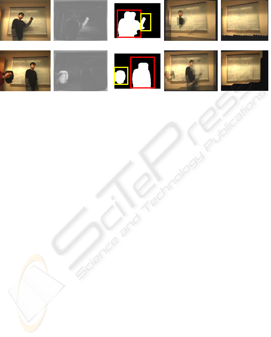
Figure 8 shows two capture sequences
containing moving objects, temporarily stationary
objects, and multiple objects. The snapshot of the
top sequence is from when the person stopped
walking but is moving his arm holding a coffee cup.
The snapshot of the bottom sequence is from when
the person by the board stops and the person to the
left pops his head into the field of view. Figures 8(a,
f) show the follow camera images. Figures 8(b, g)
show difference images from the paired lead camera
image (not shown). Figures 8(c, h) demonstrate
composite motion masks. In the top sequence the
arm motion is an actual motion mask while the
stationary person’s mask is a re-projection from
surrounding frames. Similarly, for the bottom
sequence, the person on the left is identified with a
regular motion mask and the stationary person’s
mask is a re-projection. Despite the scene motion,
we can properly identify the moving and stationary
objects. Figures 8(d, i) depict a naïve ULR where
the images with the moving objects are sometimes
selected for rendering. Figures 8(e, j) show our
improved images using our modified ULR.
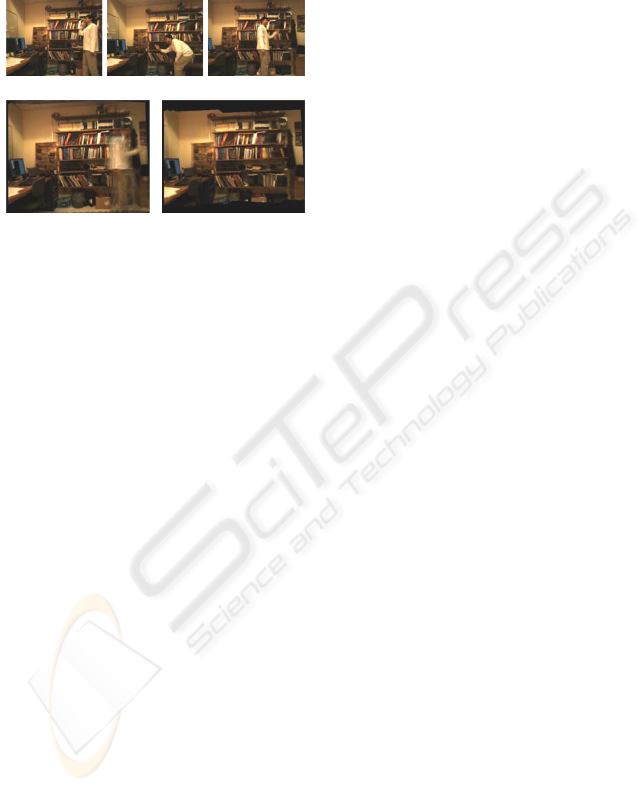
Figure 9 contains example images for an office
scene. In this example, an intruder attempted to
cover and move in front of the scene during capture.
Nevertheless, since the lag camera and object are in
motion, the space-time sampling allows us to
acquire images of the background even from
viewpoints where the background surface was
temporarily occluded. Figures 9(a-c) demonstrate
captured images and Figures 9(d, e) show novel
views without and with correct background
sampling, respectively.
Figure 6: Processing Pipeline. (a) is the original image from a follow camera, (b) is the warped image of its paired lead
camera, (c) is the difference image and (d) is the computed mask. All the images are from the “walk” scene and the follow-
to-lead camera viewpoint distance is 0.351 cms.
(a) (b) (c) (d)
Figure 7: Stop Motion. (a)(b)(c) are difference images of
3 frames from the “walk-stop-walk” scene. Since motion
stops, difference (b) is small. To solve this problem, the
mask (d) and (f) are re-projected to the viewpoint of (b)
to obtain mask (e).
(
a
)
(
b
)
(
c
)
(
d
)
(
f
)
(
e
)
LAG CAMERA: A MOVING MULTI-CAMERA ARRAY FOR SCENE ACQUISITION
105
Our current lag camera implementation only uses
image pairs when the distance between follow
camera and lead camera is less than a threshold
(currently set at 1 cm). This enables us to identify
motion but only for camera motions that are friendly
to the intended lag camera design. Ignored images
are discarded. Furthermore, if the scene contains
occluders that occlude other occluders and they stop
and then continue, the handling for stop-motion can
be incorrect.
Currently we assume the background is static,
the environment is mostly diffuse, and there are no
major changes in illumination. Objects in the scene
may produce shadows on the background,
particularly near the object contour. We do not
compensate for these shadows. Furthermore, the
Gaussian blurring we perform to smooth the
difference images makes object boundaries fuzzy.
Thus, to be conservative, our motion masks are
slightly dilated to ensure objects are fully contained.
8 CONCLUSIONS AND FUTURE
WORK
We have introduced the lag camera design and
demonstrated an example implementation. A lag
camera obtains space-time samples of an
environment while the camera is moving through an
environment containing moving objects. The camera
obtains more than one sample from approximately
the same viewpoint but at different and nearby
instances in time. This reduces the problem of
moving cameras in a moving environment to the
case of a static camera in a moving environment. In
particular, we demonstrate that a lag camera can
easily and interactively detect multiple moving or
temporarily stationary objects while itself
continuously moving through the environment.
Furthermore, the scene behind moving occluders is
captured by the lag camera thus enabling more
efficient environment acquisition, even in busy and
actively-used environments.
There are several avenues of future work. First,
we would like to extend our prototype to use tighter
motion masks by “undoubling” the difference
images. Second, we wish to add vision-based
camera pose estimation to our system to replace our
mechanical arm. Since the lag camera pairs are from
nearby points, we do not expect to have very
stringent camera pose estimation requirements. This
would enable us to capture large and actively in-use
scenes using either a robotic platform carrying a lag-
camera or a hand-held/head-mounted lag camera.
Third, we are pursuing the explicit acquisition of
foreground motion from a moving lag camera.
Figure 8: Multiple Motions. Top row shows the “walk-hi-walk” scene and bottom row shows the “walk-head-walk” scene.
(a) and (f) are original frames, (b) and (g) are corresponding difference images (lead camera images not shown). Since,
p
erson’s body stops, difference (b) is only for the arm motion. Similarly, difference (g) is only for head motion. To obtain
motion mask (c) and (f), we re-project neighboring masks to this viewpoint (red rectangle) and then “or” the mask of the
arm (head) motion (yellow rectangle). (d, i) and (e, j) are synthesized novel views without and with object detection.
(
a
)
(
b
)
(
c
)
(
d
)
(
e
)
(
f
)
(g)
(
h
)
(
i
)
(j)
GRAPP 2006 - COMPUTER GRAPHICS THEORY AND APPLICATIONS
106
Finally, since cameras are getting smaller and
faster everyday, we are very excited about other lag
camera configurations that capture more space-time
samples using additional cameras and in a smaller
footprint. This enables the acquisition of faster
moving scenes. In general, we look forward to
future work with lag cameras and believe it could
lead to significant new research ideas in acquisition,
3D reconstruction, and space-time processing.
REFERENCES
A. Agarwala, C. Zheng, C. Pal, M. Agrawala, M. Cohen,
B. Curless, D. Salesin, R. Szeliski. Panoramic Video
Textures. ACM Transactions on Graphics
(Proceedings of SIGGRAPH 2005), pp. 821-827,
2005.
C. Buehler, M. Bosse, L. McMillan, S. Gortler, and M.
Cohen. Unstructured Lumigraph Rendering. Proc.
ACM Conference on Computer Graphics
(SIGGRAPH), pp. 425-432, 2001.
J. Davis, D. Nehab, R. Ramamoorthi, and S.
Rusinkiewicz, Spacetime Stereo: A Unifying
Framework for Depth from Triangulation, IEEE
Transactions on Pattern Analysis and Machine
Intelligence, Vol. 27, No. 2, February 2005.
S. Gortler, R. Grzeszczuk, R. Szeliski, and M. Cohen. The
Lumigraph. Proc. ACM Conference on Computer
Graphics (SIGGRAPH), pp. 43—54, 1996.
M. Levoy and P. Hanrahan. Lightfield rendering. Proc.
ACM Conference on Computer Graphics
(SIGGRAPH), pp. 31--42, 1996.
Y. Li, J. Sun, and H.-Y. Shum, Video Object Cut and
Paste, ACM Trans. on Graphics (Proc. of SIGGRAPH
2005), pp. 595-600, 2005.
W. Matusik and H. Pfister. 3D TV: a Scalable System for
Real-time Acquisition, Transmission, and
Autostereoscopic Display of Dynamic Scenes. ACM
Trans. Graph. (SIGGRAPH Proceeding) 23, 3, pp.
814–824, 2004.
T. Naemura, J. Tago, and H. Harashima. Realtime video-
based modeling and rendering of 3d scenes. IEEE
Computer Graphics and Applications, Vol. 22, No. 2,
pp. 66-73, March/April 2002.
A. Schödl, R. Szeliski, D. H. Salesin, and I. Essa. Video
textures. Proc. ACM Conference on Computer
Graphics (SIGGRAPH), pp. 489-498, July 2000.
R. Tsai, A Versatile Camera Calibration Technique for
High-Accuracy 3D Machine Vision Metrology Using
Off-the-Shelf TV Cameras and Lenses, IEEE Journal
on Robotics and Automation, RA-3:4, pp. 323-344,
1987.
H. Wang and R. Yang, Towards Space-Time Light Field
Rendering, ACM SIGGRAPH Symposium on
Interactive 3D Graphics and Games (I3D), 2005.
J. Wang, P. Bhat, A. Colburn, M. Agrawala and M.
Cohen. Interactive Video Cutout. ACM Trans. on
Graphics (Proc. of SIGGRAPH), pp. 585-594, 2005.
J.C. Yang, M. Everett, C. Buehler, and L. McMillian. A
Real-time Distributed Light Field Camera.
Proceedings of the 13th Eurographics Workshop on
Rendering, pp. 77–86, 2002.
L. Zhang, B. Curless, and S. Seitz, Spacetime Stereo:
Shape Recovery for Dynamic Scenes, IEEE Computer
Society Conference on Computer Vision and Pattern
Recognition (CVPR '03), Volume 2, pp. 367-374,
2003.
Figure 9: Background Sampling. We can sample the
background of “motion in office” scene even with
significant object motion. (a-c) are frames captured and
(d
-e
)
are novel views without and with motion masks.
(a) (b) (c)
(
d
)
(
e
)
LAG CAMERA: A MOVING MULTI-CAMERA ARRAY FOR SCENE ACQUISITION
107
