
PRECISE MODELING OF ARCHEOLOGICAL ARTIFACTS
Junta Doi, Wataru Sato, Masahiko Hoshi, Shinji Morishita, Tomohiro Morita, Kota Sudo, Youhei Nakanishi
Chiba Institute of Technology, Department of Computer Science
Keywords: Matrix format data structure, Topology assigned modeling, 3D shape processing, Archeological artifact,
Depth-to-depth transformation operator.
Abstract: Precise shape reconstruction of archeological artifacts within 0.01 mm 3D resolutions are reported based on
our proposal of a practical, accurate, topologically robust and ranging error resistive shape modeling procedure
that approximates a real 3D object, with the matrix-format data structure, for the resulting shape processing.
Examples of the shape processing are based on the premise of the virtual manipulation of the 3D shape. Radial
distance of each scanning point is measured by laser triangulation. A face array listing, which defines the
sampling point connectivity and the shape of the mesh, is assigned to meet the desired meshing. Topologically
stable meshing, and hence, an accurate approximation, free from the shape ambiguity unavoidable in the so-
called ICP (Iterative Closest Point) modeling, is then accomplished. This proposal allows not only the precise
shape modeling, but also virtual shape manipulation for various trainings and restorations.
1 INTRODUCTION
Attempts to measure the shape of objects and to
construct geometric models have a long history.
There are a great number of books, review articles
(Scott et al., 2003; and Blais, 2004), papers (Turk et
al., 1994; Levoy et al., 2000; Rusinkiewicz et al.,
2001; Godin et al., 2002; and Pauly et al, 2003), and
products (Simple3D, 2005) dealing with the
problems.
This study is to provide technology that would re-
construct the objects, such as, archeological artifacts
accurately and precisely as they are in a usually
noisy environment. A 3D shape processing for
restoration is another purpose of the proposal.
Surface models with unorganized triangular meshes
were built based, for instance, on the so-called ICP
algorithm, from triangulation scanners so far. The ICP
algorithm is well proven; however, it is noise-sensitive
and hence, shape ambiguity becomes unavoidable. In
general, the presence of noise is typical for the scan-
ning process. Retrieving the surface topology from
the surface geometry as the algorithm is a difficult
problem, especially when the ranging noise is
unavoidable. Many attempts have been made to
overcome the problem; however, there is no known
algorithm that has theoretical guarantees, without
any assumptions, in the presence of noise (Dey et
al., 2004). Most scientific efforts are toward the
unorganized meshing. Contrary to the procedures,
topology is first assigned in our procedure, enabling
the matrix-format organized meshing and versatile 3D
shape processing.
The ranging noise arises mostly from the oblique
reflection of the incident laser beam on the local
surface. In the 3D shape modeling procedure, this
noise problem is serious and inevitable. However,
few articles discussed the problem. To reduce the
noise, a large object model with rather flat surfaces
is to be employed. The surface polishing is most
effective for a reliable triangulation. These measures
are, however, not applicable to most of the objects
that should be treated as they are.
S
S
u
u
c
c
c
c
e
e
s
s
s
s
i
i
v
v
e
e
s
s
h
h
a
a
p
p
e
e
m
m
o
o
d
d
i
i
f
f
i
i
c
c
a
a
t
t
i
i
o
o
n
n
i
i
s
s
a
a
p
p
p
p
l
l
i
i
e
e
d
d
t
t
o
o
t
t
h
h
e
e
o
o
r
r
g
g
a
a
n
n
i
i
z
z
e
e
d
d
a
a
n
n
d
d
p
p
o
o
i
i
n
n
t
t
-
-
l
l
o
o
c
c
a
a
t
t
a
a
b
b
l
l
e
e
m
m
o
o
d
d
e
e
l
l
u
u
s
s
i
i
n
n
g
g
i
i
n
n
t
t
u
u
i
i
t
t
i
i
v
v
e
e
m
m
a
a
t
t
r
r
i
i
x
x
-
-
t
t
y
y
p
p
e
e
o
o
p
p
e
e
r
r
a
a
t
t
o
o
r
r
s
s
e
e
n
n
a
a
b
b
l
l
i
i
n
n
g
g
t
t
h
h
e
e
q
q
u
u
a
a
n
n
t
t
i
i
t
t
a
a
t
t
i
i
v
v
e
e
s
s
h
h
a
a
p
p
e
e
e
e
v
v
a
a
l
l
u
u
a
a
t
t
i
i
o
o
n
n
a
a
n
n
d
d
C
C
A
A
D
D
c
c
o
o
m
m
p
p
a
a
t
t
i
i
b
b
i
i
l
l
i
i
t
t
i
i
e
e
s
s
.
.
2 MODELING AND SCANNING
In an illustration of a solid model data structure in
Fig. 1, a pentahedral volume element, in which the
peripheral surface is covered with a rectangular mesh,
small enough to approximate the curved object surface,
is to be measured to approximate the object shape. A
quadrilateral mesh Sa, consisting of four surface
points, a, b, c and d, is one of the sampling points
on the object surface. Points A, B, C and D are mesh
points consisting of a rectangular mesh SA on the unit
331
Doi J., Sato W., Hoshi M., Morishita S., Morita T., Sudo K. and Nakanishi Y. (2006).
PRECISE MODELING OF ARCHEOLOGICAL ARTIFACTS.
In Proceedings of the First International Conference on Computer Graphics Theory and Applications, pages 331-334
DOI: 10.5220/0001356803310334
Copyright
c
SciTePress

cylinder surface. The rectangular mesh SA is a
perspective projection of the quadrilateral mesh Sa
to the unit cylinder surface, and vice versa. Each
radial distance of the object surface point from the
axis of rotation (z- axis), for instance, “ra, rb,
· ·” is
sequentially measured.
A vertex array listing, which is called “geometry”
and represents the geometric coordinate values in 3D
space is shown in Table 1. The face (mesh) array listings
for the Sa and SA are shown in Tables 2. Four other
surfaces comprised of the wedge shaped pentahedral
volume element are similarly defined (tables not
shown).The listing is called “topology” and defines
the shape of the face (number of vertices or edges)
and also defines the listing sequence of the vertices
or connectivity. The listing sequence of the vertices
in the face list defines the normal vector direction of
the face and determines on which side of the face the
solid part of the object exists.
As shown in Fig. 1 and Table 2, the variation in
the radial distance of a, in principle, has no effect on
the connectivity array of the face, if point a locates
along the radial line segment O1-a or O1-A. This
relation is also valid for the other points b, c, and d.
Therefore, the connectivity array of the mesh is
conserved if the four points similarly locate along
each radial line. The vertex connectivity of Sa is the
same as that on the unit cylinder, SA as shown in Fig.
1 and Table 2. This means that the face array listing
assigned for the unit surface SA is valid for the object
surface Sa. If every radial distance is large enough,
the surface shape becomes totally planar. This
procedure is valid for planar surface as well.
Our data format is a raster scan type or a matrix
format as described above and it is as follows.
r = [r
ij
] =
⎥
⎥
⎥
⎦
⎤
⎢
⎢
⎢
⎣
⎡
nmn2n1
2m2221
1m1211
rrr
rrr
rrr
Λ
ΜΟΜΜ
Λ
Λ
(1)
An element r
ij
represents the radial distance of a
sampled surface point at the angular position “j” and
at the vertical position “
i” in the scanning This matrix
can easily locate an arbitrary point on the object only
by specifying “
i” and “j.”
The same matrix-formatted shape modifying
operators or depth-to-depth operators are applicable.
An example of the 128x128 positive depth-to-depth
operator is shown in Fig. 2 (left). Another example of
the versatile operator is shown in Fig. 2 (center and
right). A bread arc-board (center) and a customized
depth-to-depth operator (right), which may be one of
our modeled results, are shown. The operator shape can
be pressed on the 3D models to make its replica. Bit-
map characters and symbols are printed on any 3D
geometric models. The geometric models are fused
Table 1: Vertex array listing (geometry) for the quadri-
lateral surface meshes SA (left) and Sa (right) in Fig. 1.
Vertex r θ z
SA: A 1 0 z1
B 1 θ z1
C 1 θ z2
D 1 0 z2
Vertex r θ z
Sa: a ra 0 z1
b rb θ z1
c rc θ z2
d rd 0 z2
Table 2: Face array listing (topology) for the meshes Sa
(top) and Sa (bottom).
Figure 1: The mesh structure of the solid model cylinder. The
points a, b, c, and d are scanned points on the object surface,
while the points A, B, C and D are on the unit cylinder. The
mesh ABCD is a perspective projection of the object
surface mesh abcd on the unit cylinder surface, and vice
versa. Variation in the radial distance of point “a” has no
effect on the vertex connectivity of the mesh Sa, if “a” locates
along the “O1-A.” This is valid for other three points.
Scanning is aligned to successively follow the rectangular
mesh SA. “T1” is the triangulation sensor.
Figure 2: A positive depth-to-depth transformation operator
(128x128 meshes, left). A bread arc-board (centre), instead of
the planar board, and a customized 3D operator, which may
be a thus reconstructed model of the real object. Convolution of
the reconstructed model operator fuses two 3D shapes
together.
Face 1 2 3 4
Sa a b c d
SA A B C D
GRAPP 2006 - COMPUTER GRAPHICS THEORY AND APPLICATIONS
332

together with the 3D operators by convolution.
An object such as a statue is placed on a turntable
which is driven by a geared pulse motor with angular
resolution of 0.02 degrees. This means that the
horizontal (peripheral or horizontal) resolution is 0.015
mm at the radius of 43 mm and there are a maximum
of 18,000 horizontal meshes in one 360 degree turn.
The translational resolution of the vertical slider, which
is also driven by a geared pulse motor, is 0.001 or
0.015 mm with a maximum stroke of 500 mm. There
are 33,333 or 50,000 vertical meshes at maximum in
the full stroke. Therefore, the maximum number of
the quadrilateral meshes is 600 or 900 million.
A triangulation sensor with a diode laser is installed
on the vertical slider. The spot size on the object
surface is 0.3 or 0.1 mm in diameter. A sensing range
from 250 mm to 750 mm at maximum is produced here
with a resolution of 0.001 mm at best. In the procedure,
the measurement is general and not limited to this type
of sensing. As a modeling/rendering system, we
prepared solid model interfaces for the popular 3D
computer graphics and computer-aided design systems.
3 RESULTS AND DISCUSSION
The desired meshing, for instance, the rectangular SA
is first assigned for the sampling point connection and
then the vertex array listing is continuously updated.
Our procedure results in the “B-reps” model, which
describes a 3D object as a set of the organized
quadrilateral meshes.
A replica of an Egyptian relief is modeled as
shown in Figs. 3 and a fossil trilobite in Fig. 4. Other
replica examples are: a human skull in Fig. 5, the
Parthenon frieze in Fig. 6, and the Greek cavalier in Fig.
8. In these modeling, if the triangulation errors are
detected, depth-to-depth transformation operators (A
= [a
ij
], i= j = 3, 5 or 7) are applied to the data matrix
(1) to smooth the local surface or the noisy points are
replaced with the surrounding data. This type of shape
modifying operations, including a transcription
example in Fig. 7 and shape modification in Figs. 9
and 10, are applicable only if the output data is a
matrix-format as this procedure. The noise-eliminated
model is also observed to closely follow the shape of
the real object.
The matrix type data is convenient and essential
for modifying a local shape when locating the target
position. In Figs. 9 and 10, a bruise on the right cheek
is modified to try to restore and the broken nose is
similarly restored. These are supposing the restoration
of a broken or damaged artifact or for virtual
training of, for instance, cosmetic surgery.
Figure 3: A photograph and the shaded images of the
reconstructed model (right) of an Egyptian relief.
Horizontal and vertical resolutions are 0.01 mm and 0.015
mm, respectively. Depth resolution is 0.001 mm.
Figure 4: A photograph (left) and the shaded image of the
modeled result of a fossil trilobite (right). Spatial
resolutions are 0.01 mm both in horizontal and vertical
directions. Depth resolution is 0.001 mm.
Figure 5: A photograph (left) and the shaded image of the
modeled result of a plaster skull (right). Resolutions in
rotational direction is 0.02 deg. and in vertical 0.015 mm.
Figure 6: A photograph (left) and the shaded image of the
modeled (left) of the Parthenon frieze, Charioteers replica
(The British Museum). Resolutions in horizontal and vertical
directions are 0.01 mm. Depth resolution is 0.001 mm.
PRECISE MODELING OF ARCHEOLOGICAL ARTIFACTS
333
The modeling accuracy depends on the rotational
and translational positioning, and distance-sensing.
The mal-aligned positioning results in a shape distor-
tion, but still generates topologically stable models.
4 CONCLUSIONS
Some precise 3D models, within 0.01 mm 3D
resolutions, are demonstrated based on the topology-
assigned modeling procedure. The simple,
automatic, geometrically accurate and precise,
topologically stable, robust and noise-resistive object
modeling, with matrix-format meshes, for
archeological and cultural heritage applications. The
noise problem inherent in the triangulation scanning,
fatal in the so-called “retrieve topology from geometry”
algorithm, is solved using the matrix format operators
for practical usage in the exchange for some spatial
resolution reduction. We expect considerable utility
in the practical approximation and 3D shape
processing.
REFERENCES
Blais, F., 2004, Review of 20 Years of Range Sensor
Development, Journal of Electronic Imaging, 13 (1),
231-240.
Dey, T., Goswami, S., 2004, Provable Surface Reconstruc-
tion from Noisy Samples, Annual Symposium on
Computational Geometry, In Proceedings of 20th Annual
Symposium on Computational Geometry, 330-339.
Godin, G., Beraldin, J., Taylor, J., Cournoyer, L., El-
Hakim, S., Baribeau, R., Blais, F., Boulanger, P.,
Domey, J., Picard, M., 2002, Active Optical 3D
Imaging for Heritage Applications IEEE Computer
Graphics and Applications, 22, 24-36.
Levoy, M., Pulli, K., Curless, B., Rusinkiewicz, S., Koller,
D., Pereira, L., Ginzton, M., Anderson, S., Davis, J.,
Ginsberg, J., Shade, J., Fulk, D., 2000, The Digital
Michelangelo Project; 3D Scanning of Large Statues,
In Proceedings of Siggraph 2000, 131-144.
Rusinkiewicz, S., Levoy, M., 2001, Efficient Variants of
the ICP Algorithm, In Proceedings of the 3rd
International Conference on 3-D Digital Imaging and
Modeling (3DIM ’01), 145-152.
Scott, W., Roth, G., Rivest, J., 2003, View Planning for
Automated Three-Dimensional Object Reconstruction
and Inspection, ACM Computing Surveys, 35(1), 64-
96.
Simple3D, 2005, 3D Scanners, Digitizers, and Software
for Making 3D Models and 3D Measurements,
http://www. simple3d.com/
Pauly, M., Keiser, R., Kobbelt, L., Gross, M., 2003, Shape
Modeling with Point-Sampled Geometry, ACM
Transactions on Graphics (TOG), 22 (3), Special
issue: Proceedings of ACM SIGGRAPH, 641-650.
Figure 7: The modeled frieze replica in Fig. 7 is trans-
cribed onto a cylinder on the supposition of a vase design.
The left part of this figure corresponds with that of Fig. 6.
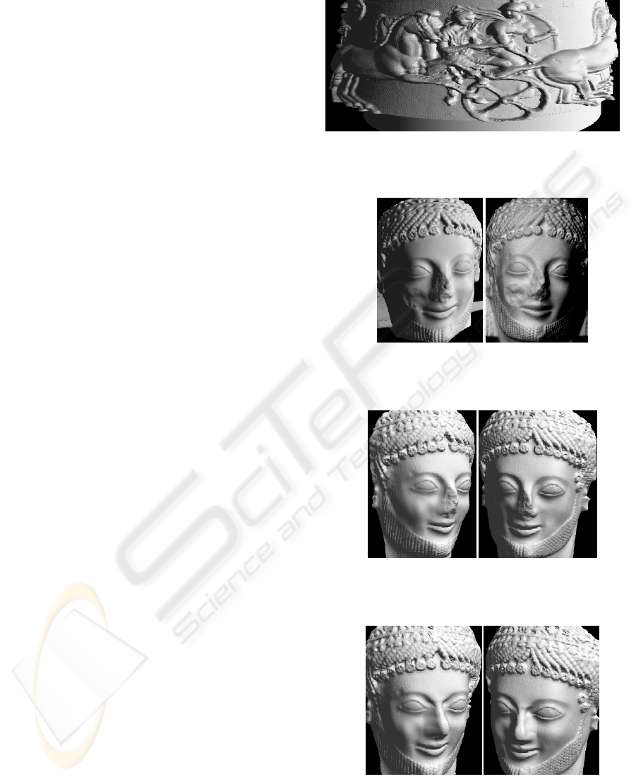
Figure 8: A photograph (left) and the shaded image of the
modeled result (right) of a plaster statue (Greek cavalier
Rampin). Resolutions are similar to those in Fig. 5.
Figure 9: The cheek bruise in the model in Fig. 8 is
restored using similar operators in Fig. 2 (left). The plump
(left) and the sunken cheeks (right) are depicted.
Figure 10: The cheek bruise and the broken nose are
restored. The nose is restored by implanting another nose in a
Greek mask and then shape modified using a depth-to-depth
trans-formation operator in Fig. 2 (left). As the data structure
is matrix-format, detailed procedures are not shown here.
GRAPP 2006 - COMPUTER GRAPHICS THEORY AND APPLICATIONS
334
