
APPEARANCE BASED PAINTINGS RECOGNITION FOR A
MOBILE MUSEUM GUIDE
Claudio Andreatta
∗
ITC-irst Istituto per la ricerca scientifica e tecnologica
38050 Povo, Trento, Italy
Fabrizio Leonardi
ITC-irst Istituto per la ricerca scientifica e tecnologica
38050 Povo, Trento, Italy
Keywords:
appearance based recognition, image retrieval, color normalization.
Abstract:
This paper presents a prototype of a visual recognition system for a handheld interactive museum guide.
Contextualized information about museum drawings may be obtained by the user, without any knowledge
about how the system works by simply pointing a palmtop camera towards the painting and taking a shot. The
system was tested and performance was found to be satisfactory in challenging environment conditions.
1 INTRODUCTION
Human-computer interaction has become an increas-
ingly important part of our daily lives, and many re-
search projects are focused on finding non intrusive,
simple, and natural technology to allow a casual user
to interact with complex systems. In this context, vi-
sion based interfaces have many advantages.
New and interesting possibilities are offered by the
employment of Personal Digital Assistants (PDA).
Nowadays they can not only manage personal in-
formation, such as contacts, appointments, and to-
do lists, but also also connect to the Internet, act as
global positioning system (GPS) devices, run multi-
media software and be equipped witch sensors such
as digital cameras and microphones.
In this paper we propose a system which uses vi-
sion recognition techniques to provide a museum vis-
itor contextual information about a painting as in
(Robertson et al., 2004) and (Albertini et al., 2005).
In our test scenario the visitor brings a PDA equipped
with a digital camera. To ask for information about
a picture, the visitor simply points the PDA camera
to the painting and pushes a button. The PDA moni-
tor notifies the user whether the system recognize the
museum painting or about the impossibility of analyz-
ing the image (e.g. the item was not correctly framed
or no image analysis was possible due to poor light
condition).
In the following we describe the system architec-
∗
Corresponding author: andreatta@itc.it
DB
Paintings
DB
Presentation
Vision
Engine
Recognition
Presentation
HTTP
HTTP
SERVER SIDECLIENT SIDE
Server
PDA with camera
Figure 1: Simplified system architecture.
ture, the vision recognition engine and the image
processing techniques involved in the preprocessing
stage (Section 2). We present and discuss in the con-
cluding section the experimental results (Section 3).
2 SYSTEM ARCHITECTURE
The simplified system architecture is depicted in Fig-
ure 1. The PDA device is a HP IPAQ 5550 with
128 Mb and Intel X-Scale PXA255 400 Mhz proces-
sor and it is equipped with a wireless card, support-
ing WiFi connectivity and a digital camera LifeView
FlyCam CF 1.3M. The user interface was developed
in C# and runs on a Windows Pocket PC 2003 OS.
The vision recognition engine and the presentation
provider on the server side are implemented in C++
and run on a Linux machine. All the communications
138
Andreatta C. and Leonardi F. (2006).
APPEARANCE BASED PAINTINGS RECOGNITION FOR A MOBILE MUSEUM GUIDE.
In Proceedings of the First International Conference on Computer Vision Theory and Applications, pages 138-142
DOI: 10.5220/0001359901380142
Copyright
c
SciTePress

(a) (b)
Figure 2: (a) The PDA in camera mode, (b) A drawing shot
example.
among the client and the servers use a standard http
protocol.
When the interface is in camera mode, the display
represents what the camera frames. When the mu-
seum visitor wishes information about a painting, he
points the camera toward the painting and pushes a
query button. It is preferable that the whole draw-
ing, including the frame, be represented. The picture
is sent then to the recognition engine. On a positive
recognition the PDA provides a multimedia presen-
tation of the museum painting, otherwise a feedback
about the impossibility of analyzing the image will be
shown in order to help the user in better using the sys-
tem.
2.1 Vision Recognition Engine
The visual recognition engine purpose is to classify an
unknown query image submitted by the museum visi-
tor using the PDA. The query image is compared to all
the images in the paintings database and for each dif-
ferent painting (represented by one or more images) a
similarity score is computed and evaluated.
The database is built following the learning by
example paradigm. Several images of the museum
paintings, annotated with a unique identifier, are ac-
quired with the palmtop. In the learning phase the
behavior of a potential visitor is simulated: the shots
are taken not only from a frontal view but at differ-
ent angles and at different distances (Figure 3). The
region of interest (ROI) for further processing is ob-
tained considering only a part of the shot, cropping
the picture: the height and width of the ROI are 3/4
of the original height and width (240x320). In order
to simulate even more camera positions, the ROI is
moved in 25 different positions. In the query phase,
the ROI is centered and it represents the inner and
more relevant part of the picture.
Figure 3: Learning phase: the pieces pictures are acquired
simulating a casual visitor position. It is required that all
the piece is depicted in the shot.
The visual recognition engine exploits research re-
sults from the field of image retrieval. Many research
papers and systems have been presented for image re-
trieval based on low level visual feature with the goal
of preserving effectiveness minimizing the size of the
image descriptors and the response time (Brunelli and
Mich, 2000). The computation of the feature vector
and the retrieval itself are performed by a modified
version of the content based image retrieval system
COMPASS (Brunelli and Mich, 2000), (Andreatta,
2004) ,(Andreatta et al., 2005).
The following low level features histograms are
considered to describe the ROI visual content:
- Intensity: 8 bin,
- Edges magnitude (log mapped): 8 bin,
- Edges along vertical axis (log mapped): 8 bin,
- Edges along horizontal axis (log mapped): 8 bin,
- Hue: 8 bin,
- Saturation: 8 bin.
- Intensity co-occurrence: 4 × 4 bins bidimensional
histogram,
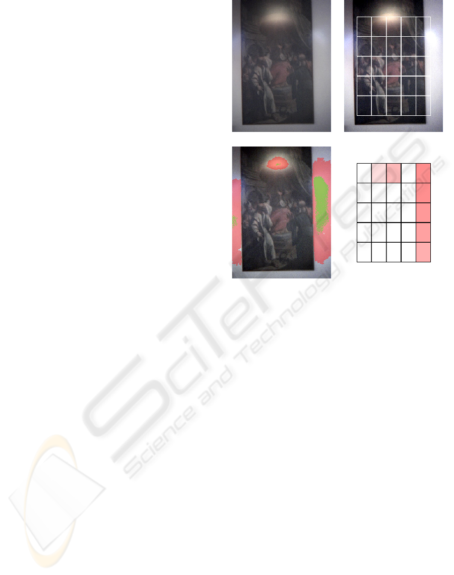
The ROI is partitioned in a 5 × 5 fixed grid in or-
der to retain spatial information (see Figure 4(a)) and
each region, denoted as ROI
r
(r ∈ [0, 24]), is de-
scribed independently.
Histograms can be represented as vectors and their
difference can be quantified by a metric defined in the
associated vector space. A widely used family of met-
rics is the L
p
family defined as:
L
p
(x, y)=
N
i
|x
i
− y
i
|
1/p
,p≥ 1 (1)
The L
1
metric, also known as the Manhattan norm,
provides good results and supports efficient compari-
son. The distance (dissimilarity) between two images
is defined as:
d(x, y)=
1
K
r
W
r
L
p
(x
r
,y
r
) (2)
APPEARANCE BASED PAINTINGS RECOGNITION FOR A MOBILE MUSEUM GUIDE
139
where the x
r
y
r
are the vector descriptors of the image
region ROI
r
, W
r
are the weights associated to each
region and K is a normalizing factor.
The recognition score is computed by inspecting
the nearest items in the feature space. Let be d(n),
d(n) ∈ [0, 1], the normalized distance between the
query image and the n-th nearest item in the database
and s(n) the similarity defined as s(n)=(1− d(n)).
The recognition score obtained by class c (i.e. by a
specific museum painting) is defined as:
S(c)=
n
c
w(n
c
)s(n
c
) (3)
where n
c
is the ranking in the nearest neighbor list of
class c objects, and w(n) is a tunable weight function.
If only the nearest item in the database is considered,
the weight function is defined as w(n)=δ
1n
.
Once the recognition score is computed, the visual
recognition engine returns to the PDA the sorted list
of pointing identifiers and scores of the most relevant
hypothesis. If the score of the first hypothesis is above
a given confidence threshold the presentation corre-
sponding to the guessed painting is shown, otherwise
the client notifies the rejection to the user. The confi-
dence threshold may be tuned on the client side.
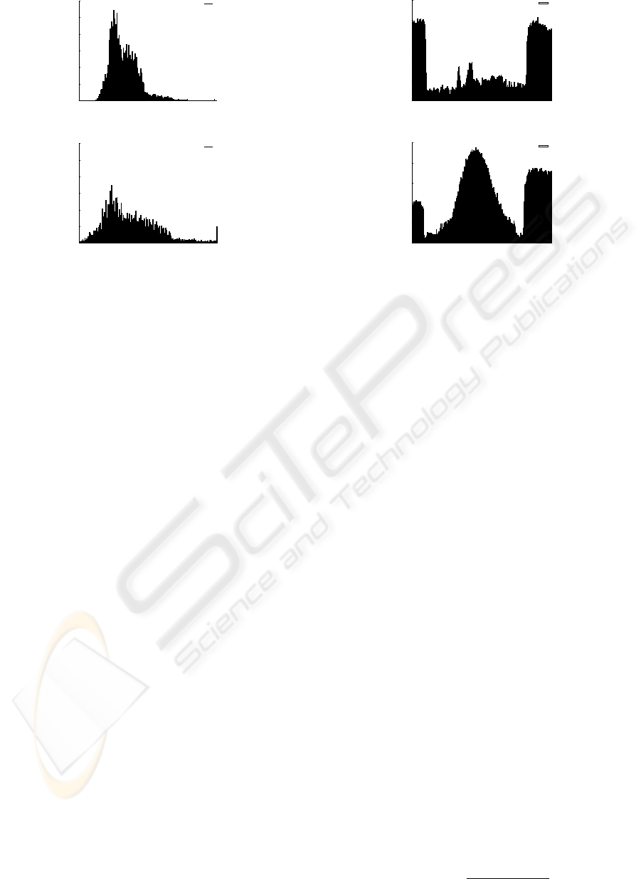
2.2 Preprocessing
The shots of museum paintings acquired by the palm-
top camera are of poor quality and characterized by
a low contrast due to limited dynamic range of the
sensor (a common problem in low cost cameras with
CMOS sensors) and poor light condition (in Figure
5(a) the graylevel intensity histogram of a sample im-
age is depicted). Moreover the paintings themselves
lack saturated colors, making the color information,
in most cases, unreliable making preprocessing stage
necessary. In order to normalize and increase the dy-
namic range of the pictures, color and intensity equal-
ization algorithms are employed.
Among the many color equalization algorithm de-
veloped do far, the two most widely used are: Gray
World (GW) (Buchsbaum, 1980) and White Patch
(WP) (Funt and Cardei, 1994). These two models
are considered alternatives to each other in methods
of color correction.
Both models try to emulate two human visual adap-
tation mechanisms: lightness constancy and color
constancy. The Gray World approach is typical of
the lightness constancy adaptation because it modifies
the dynamic range of the histogram, assuming that
the average world is gray i.e. assumes that the av-
erage of the surface reflectance over the entire scene
is gray. Alternatively, the White Patch approach is
typical of the color constancy adaptation, searching
for the lightest patch to be used as a white reference
Figure 4: Image processing flow: original image, normal-
ized image with the description grid superimposed, detected
overexposed areas (seed regions are green and the detected
blooming area red), features regions weights used in the
comparison.
similar to how the human visual system does. The
human vision system mechanism is also highly non
linear, since it can be global and local at the same
time. Among the models that compute local color
adaptation using spatial relation and image content we
can consider Land’s Retinex theory (Land, 1977). A
recent approach, called Autmatic Color Equalization
(ACE), merges the Retinex model and the GW model,
performing simultaneously global and local filtering
(Rizzi et al., 2002).
Even if local adaptive methods give the best results,
they are computational demanding for real time ap-
plications, therefore we moved to a simple and effi-
cient approach based on a variant of the GW algo-
rithm. A contrast stretching transformation was con-
sidered: the image is normalized using a piecewise
linear function whose control points are determined
by inspecting the original histogram and computing
the expected gray point as in the GW method. The
normalization method enhances the contrast of a color
image by adjusting the pixels color to span as much
as possible the entire range of available colors. The
histogram tails are cut locating the histogram bound-
aries: 0.1 percent in the black range and 0.5 percent in
VISAPP 2006 - IMAGE UNDERSTANDING
140
0
0.005
0.01
0.015
0.02
0.025
0.03
0 50 100 150 200 250
Ratio
Bins
Intensity
0
0.005
0.01
0.015
0.02
0.025
0.03
0 50 100 150 200 250
Ratio
Bins
Intensity
Figure 5: Preprocessing: original image intensity his-
togram, normalized image histogram with cutted tails.
the white range. In the acquired images, the elongated
white tail and peaks are principally due to the pres-
ence of highlights, reflections and over under exposed
areas. In order to recover an illuminant-invariant mea-
sure of the paintings color the GW algorithm is ap-
plied to the stretched image disregarding histograms
tails (see Figure 4 and 5).
Histogram stretching may introduce fictious dy-
namic so that the feature vector no longer represents
the visual content of an image. In order to avoid
this problem, a rejection mechanism based on the his-
togram characteristics was introducted. More specifi-
cally, an input image is rejected whenever:
⎧
⎪
⎪
⎪
⎨
⎪
⎪
⎪
⎩
I
mincut
>m
cut
∨ I
maxcut
<M
cut
(I
maxcut
− I
mincut
) <W
ROI
min
>m
roi
∨ ROI
max
>M
roi
(4)
where I
mincut
and I
maxcut
are the cutting points
of the histogram boundaries, (I
maxcut
− I
mincut
) is
the width of the cutted histogram and ROI
min
and
ROI
max
are the ROI maximum an minimum inten-
sity.
2.3 Inhibition of Overexposed Areas
When strong light sources are present or the paint-
ing is not correctly framed, parts of the image be-
come overexposed. Blooming effect occurs and over-
exposed areas bleed into nearby darker zones and de-
tail is lost.
In order to prevent the influence of such disruptive
effects, we developed a strategy for the detection and
inhibition of overexposed areas. Potentially overex-
posed areas are detected and marked as seeds of a
0
0.2
0.4
0.6
0.8
1
0 50 100 150 200
Intensity
Width
Intensity
0
0.2
0.4
0.6
0.8
1
0 50 100 150 200
Intensity
Width
Intensity
Figure 6: Overexposed area intensity profile: normal profile
and blooming effect profile.
region growing algorithm. The region growing pro-
cedure tries to follow the blooming effect assuming
that the intensity function is smooth and monotoni-
cally decreasing. This assumption looks to be reason-
able by inspecting the intesity profile of such areas
(Figure 6).
We define as overexposed region seed an image re-
gion R that, after the preprocessing stage, has the fol-
lowing properties:
R = {p |∀I(p) ≥ I
min
and S(p) ≤ S
max
}
A(R) ≥ A
min
(5)
where I is the image intensity and S the image satu-
ration.
The region growing algorithm tracing the bloom-
ing effect works as follows: for each pixel p of the
boundary of an overexposed region seed R, it grows
the region adding a new pixel q of the neighborhood
of p according the following criteria:
⎧
⎪
⎪
⎪
⎪
⎪
⎪
⎨
⎪
⎪
⎪
⎪
⎪
⎪
⎩
I(p) − I(q) ≤ I
mono
Monotonicity
I(q) ≥ I
min
Minimum I
|G(p) − G(q)|≤G
smooth
Smoothness
G(q) ≥ G
min
Plateau
(6)
where G is the gradient magnitude.
When the overexposed region has been detected, a
weighting factor is computed as:
W
r
=1−
A(R ∩ ROI
r
)
A(ROI
r
)
(7)
APPEARANCE BASED PAINTINGS RECOGNITION FOR A MOBILE MUSEUM GUIDE
141

Figure 7: The challenging environmental conditions at the
exhibition.
to attenuate the contribution of regions which may
depict overexposed areas as in Figure 4.
3 EXPERIMENTAL RESULTS
AND CONCLUSIONS
The system prototype has been tested with synthetic
images and in real application at an exhibition in
Castello del Buonconsiglio in Trento. The recogni-
tion engine achieves a perfect score with synthetic
images, but the exhibition testbed was far more in-
teresting and challenging (Figure 7). The paintings
in the exhibition were 13; in the learning phase about
43 shots for each drawing at different positions, 563
images in total, have been taken and inserted in the
recognition module database. In the testing phase 70
shots were submitted by the PDA to the recognition
engine, the following table summarizes the results:
Results
Recognized 77.14%
False positives
2.86%
Rejected
20.00%
The high rejection ratio is due to the varying illu-
mination conditions, to the presence of spotlights over
the drawings and, as already commented, upon to the
lack of dynamic range of the camera sensor. However,
from the casual user perspective, may be preferable
that the system provides feedback about the impos-
sibility of analyzing the image and how to solve this
problem instead of an incorrect classification which
would trigger the start of a misleading presentation.
A prototype of a palmtop museum guide based on
computer vision recognition techniques in a challeng-
ing environment has been presented along with en-
couraging experimental results. As future work we
foresee to enhance the recognition preformance by
submitting multiple shots and to improve the feed-
back provided in order to guide the user, in a non ob-
trusive way, to correctly frame the drawing.
ACKNOWLEDGMENTS
This work was supported by the Provincia Au-
tonoma di Trento, Italy, under the project PEACH:
Personal Experience with Active Cultural Heritage
(http://peach.itc.it) and by the European Union under
the project VIKEF: Virtual Information and Knowl-
edge Environment Framework (http://vikef.net).
REFERENCES
Albertini, A., Brunelli, R., Stock, O., and Zancanaro, M.
(2005). Communicating user’s focus of attention by
image processing as input for a mobile museum guide.
In IUI 2005, International Conference on Intelligent
User Interfaces.
Andreatta, C. (2004). CBIR techniques for object recogni-
tion. Technical Report ITC-irst T04-12-01.
Andreatta, C., Lecca, M., and Messelodi, S. (2005).
Memory-based object recognition in digital images. In
VMV 2005, Vision, Modelling, and Visualization.
Brunelli, R. and Mich, O. (2000). Image retrieval by exam-
ples. IEEE Trans. on Multimedia, 2(3):164–171.
Buchsbaum, G. (1980). A spatial processor model for object
colour perception. Journal of the Franklin Institute,
310:1–25.
Funt, B. and Cardei, V. (1994). Committee-based color con-
stancy. J.Opt.Soc.Am. A, 11(11):3011–3020.
Land, E. (1977). The retinex theory of color vision. Scien-
tific American, 237(3):2–17.
Rizzi, A., Gatta, C., and Marini, D. (2002). Color correction
between gray world and white patch. In Electronic
Imaging 2002 S. Jos, California (USA).
Robertson, Laddaga, and Kleek, V. (2004). Virtual mouse
vision based interface. In IUI 2004, International
Conference on Intelligent User Interfaces.
VISAPP 2006 - IMAGE UNDERSTANDING
142
