
IMPROVING APPEARANCE-BASED 3D FACE TRACKING USING
SPARSE STEREO DATA
∗
Fadi Dornaika and Angel D. Sappa
Computer Vision Center
Edifici O Campus UAB
08193 Bellaterra, Barcelona, Spain
Keywords:
3D face tracking, adaptive appearance models, evaluation, stereo, robust 3D registration.
Abstract:
Recently, researchers proposed deterministic and statistical appearance-based 3D head tracking methods
which can successfully tackle the image variability and drift problems. However, appearance-based meth-
ods dedicated to 3D head tracking may suffer from inaccuracies since these methods are not very sensitive to
out-of-plane motion variations. On the other hand, the use of dense 3D facial data provided by a stereo rig
or a range sensor can provide very accurate 3D head motions/poses. However, this paradigm requires either
an accurate facial feature extraction or a computationally expensive registration technique (e.g., the Iterative
Closest Point algorithm). In this paper, we improve our appearance-based 3D face tracker by combining an
adaptive appearance model with a robust 3D-to-3D registration technique that uses sparse stereo data. The re-
sulting 3D face tracker combines the advantages of both appearance-based trackers and 3D data-based trackers
while keeping the CPU time very close to that required by real-time trackers. We provide experiments and
performance evaluation which show the feasibility and usefulness of the proposed approach.
1 INTRODUCTION
The ability to detect and track human heads and
faces in video sequences is useful in a great num-
ber of applications, such as human-computer in-
teraction and gesture recognition. There are sev-
eral commercial products capable of accurate and
reliable 3D head position and orientation esti-
mation (e.g., the acoustic tracker system Mouse
[www.vrdepot.com/vrteclg.htm]). These
are either based on magnetic sensors or on spe-
cial markers placed on the face; both practices are
encumbering, causing discomfort and limiting nat-
ural motion. Vision-based 3D head tracking pro-
vides an attractive alternative since vision sensors
are not invasive and hence natural motions can be
achieved (Moreno et al., 2002). However, detecting
and tracking faces in video sequences is a challeng-
ing task.
Recently, deterministic and statistical appearance-
based 3D head tracking methods have been proposed
and used by some researchers (Cascia et al., 2000;
∗
This work was supported by the Government of Spain
under the CICYT project TIN2005-09026 and The Ram
´
on
y Cajal Program.
Ahlberg, 2002; Matthews and Baker, 2004). These
methods can successfully tackle the image variabil-
ity and drift problems by using deterministic or sta-
tistical models for the global appearance of a special
object class: the face. However, appearance-based
methods dedicated to full 3D head tracking may suf-
fer from some inaccuracies since these methods are
not very sensitive to out-of-plane motion variations.
On the other hand, the use of dense 3D facial data
provided by a stereo rig or a range sensor can pro-
vide very accurate 3D face motions. However, com-
puting the 3D face motions from the stream of dense
3D facial data is not straightforward. Indeed, infer-
ring the 3D face motion from the dense 3D data needs
an additional process. This process can be the de-
tection of some particular facial features in the range
data/images from which the 3D head pose can be in-
ferred. For example, in (Malassiotis and Strintzis,
2005), the 3D nose ridge is detected and then used for
computing the 3D head pose. Alternatively, one can
perform a registration between 3D data obtained at
different time instants in order to infer the relative 3D
motions. The most common registration technique is
the Iterative Closest Point (ICP) (Besl and McKay,
1992). The ICP algorithm and its variants can pro-
310
Dornaika F. and D. Sappa A. (2006).
IMPROVING APPEARANCE-BASED 3D FACE TRACKING USING SPARSE STEREO DATA.
In Proceedings of the First International Conference on Computer Vision Theory and Applications, pages 310-317
DOI: 10.5220/0001364003100317
Copyright
c
SciTePress
vide accurate 3D motions but their significant com-
putational cost prohibits real-time performance.
The main contribution of this paper is a robust 3D
face tracker that combines the advantages of both
appearance-based trackers and 3D data-based track-
ers while keeping the CPU time very close to that re-
quired by real-time trackers. First, the 3D head pose is
recovered using an appearance registration technique.
Second, the obtained 3D head pose is utilized and re-
fined by robustly registering two 3D point sets where
one set is provided by stereo reconstruction.
The remainder of this paper proceeds as follows.
Section 2 introduces our deformable 3D facial model.
Section 3 states the problem we are focusing on,
and describes the online adaptive appearance model.
Section 4 summarizes the adaptive appearance-based
tracker that tracks in real-time the 3D head pose and
some facial actions. Section 5 gives some evaluation
results associated with the appearance-based tracker.
Section 6 describes the improvement step based on
a robust 3D-to-3D registration and the appearance
model. Section 7 gives some experimental results.
2 MODELING FACES
2.1 A Deformable 3D Model
In our study, we use the 3D face model Candide.
This 3D deformable wireframe model was first de-
veloped for the purpose of model-based image cod-
ing and computer animation. The 3D shape of this
wireframe model is directly recorded in coordinate
form. It is given by the coordinates of the 3D ver-
tices P
i
,i =1,...,n where n is the number of ver-
tices. Thus, the shape up to a global scale can be fully
described by the 3n-vector g; the concatenation of the
3D coordinates of all vertices P
i
. The vector g is writ-
ten as:
g = g
s
+ A τ
a
(1)
where g
s
is the static shape of the model, τ
a
the an-
imation control vector, and the columns of A are the
Animation Units. In this study, we use six modes for
the facial Animation Units (AUs) matrix A. With-
out loss of generality, we have chosen the six follow-
ing AUs: lower lip depressor, lip stretcher, lip cor-
ner depressor, upper lip raiser, eyebrow lowerer and
outer eyebrow raiser. These AUs are enough to cover
most common facial animations (mouth and eyebrow
movements). Moreover, they are essential for convey-
ing emotions.
In equation (1), the 3D shape is expressed in a lo-
cal coordinate system. However, one should relate
the 3D coordinates to the image coordinate system.
To this end, we adopt the weak perspective projection
model. We neglect the perspective effects since the
depth variation of the face can be considered as small
compared to its absolute depth. Thus, the state of the
3D wireframe model is given by the 3D head pose pa-
rameters (three rotations and three translations) and
the internal face animation control vector τ
a
. This is
given by the 12-dimensional vector b:
b =
[θ
x
,θ
y
,θ
z
,t
x
,t
y
,t
z
,τ
a
T
]
T
(2)
2.2 Shape-free Facial Patches
A face texture is represented as a shape-free texture
(geometrically normalized image). The geometry of
this image is obtained by projecting the static shape
g
s
using a centered frontal 3D pose onto an image
with a given resolution. The texture of this geomet-
rically normalized image is obtained by texture map-
ping from the triangular 2D mesh in the input image
(see figure 1) using a piece-wise affine transform, W.
The warping process applied to an input image y is
denoted by:
x(b)=W(y, b) (3)
where x denotes the shape-free texture patch and b de-
notes the geometrical parameters. Several resolution
levels can be chosen for the shape-free textures. The
reported results are obtained with a shape-free patch
of 5392 pixels. Regarding photometric transforma-
tions, a zero-mean unit-variance normalization is used
to partially compensate for contrast variations. The
complete image transformation is implemented as fol-
lows: (i) transfer the texture y using the piece-wise
affine transform associated with the vector b, and (ii)
perform the grey-level normalization of the obtained
patch.
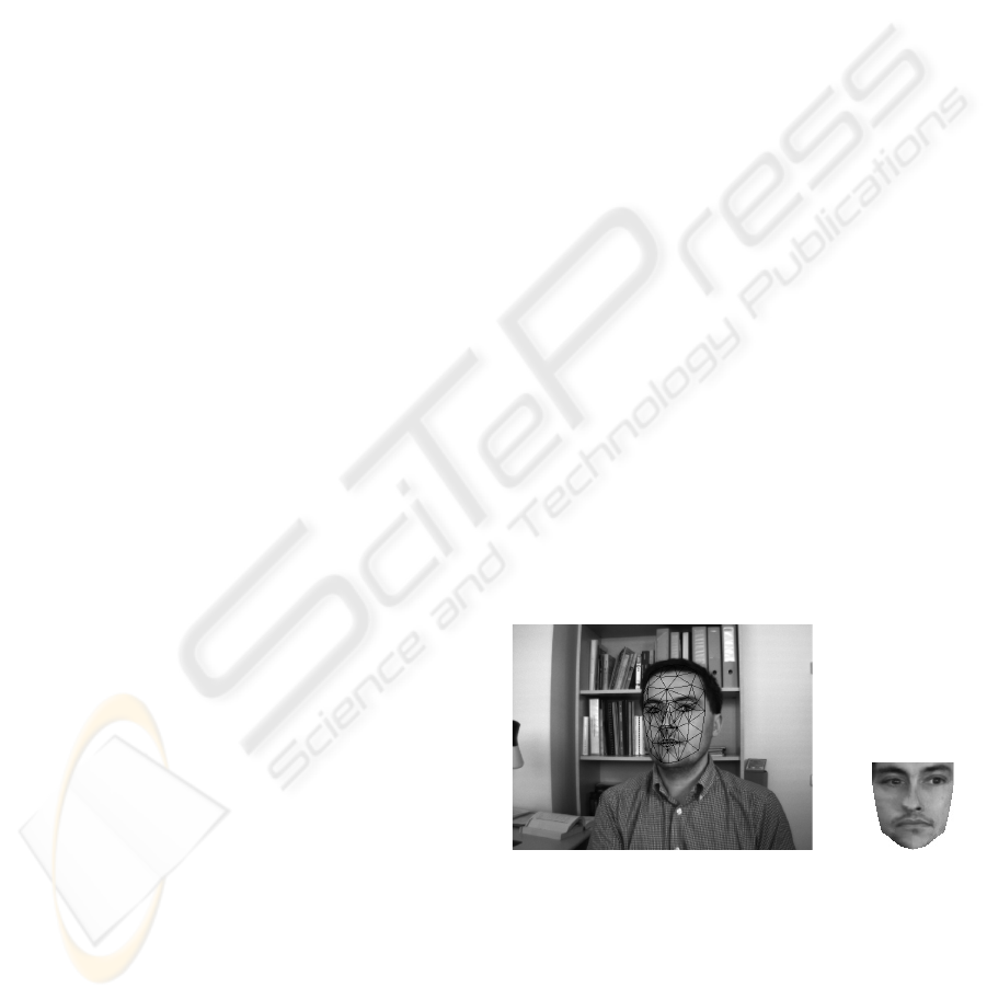
(a) (b)
Figure 1: (a) an input image with correct adaptation. (b) the
corresponding shape-free facial image.
3 PROBLEM FORMULATION
Given a video sequence depicting a moving
head/face, we would like to recover, for each frame,
the 3D head pose and the facial actions encoded by
IMPROVING APPEARANCE-BASED 3D FACE TRACKING USING SPARSE STEREO DATA
311

the control vector τ
a
. In other words, we would
like to estimate the vector b
t
(equation 2) at time
t given all the observed data until time t, denoted
y
1:t
≡{y
1
,...,y
t
}. In a tracking context, the model
parameters associated with the current frame will be
handed over to the next frame.
For each input frame y
t
, the observation is simply
the warped texture patch (the shape-free patch) as-
sociated with the geometric parameters b
t
. We use
the
HAT symbol for the tracked parameters and tex-
tures. For a given frame t,
ˆ
b
t
represents the com-
puted geometric parameters and
ˆ
x
t
the corresponding
shape-free patch, that is,
ˆ
x
t
= x(
ˆ
b
t
)=W(y
t
,
ˆ
b
t
) (4)
The estimation of
ˆ
b
t
from the sequence of images
will be presented in the next Section.
The appearance model associated with the shape-
free facial patch at time t, A
t
, is time-varying on that
it models the appearances present in all observations
ˆ
x up to time (t − 1). We assume that the appearance
model A
t
obeys a Gaussian with a center µ and a vari-
ance σ. Notice that µ and σ are vectors composed of
d components/pixels (d is the size of x) that are as-
sumed to be independent of each other. In summary,
the observation likelihood at time t is written as
p(y
t
|b
t
)=p(x
t
|b
t
)=
d
i=1
N(x
i
; µ
i
,σ
i
) (5)
where N(x; µ
i
,σ
i
) is the normal density:
N(x; µ
i
,σ
i
)=(2πσ
2
i
)
−1/2
exp
−
1
2
x − µ
i
σ
i
2
(6)
We assume that A
t
summarizes the past observations
under an exponential envelop, that is, the past obser-
vations are exponentially forgotten with respect to the
current texture. When the appearance is tracked for
the current input image, i.e. the texture
ˆ
x
t
is avail-
able, we can compute the updated appearance and use
it to track in the next frame.
It can be shown that the appearance model parame-
ters, i.e., µ and σ can be updated using the following
equations (see (Jepson et al., 2003) for more details
on Online Appearance Models):
µ
t+1
=(1− α) µ
t
+ α
ˆ
x
t
(7)
σ
2
t+1
=(1− α) σ
2
t
+ α (
ˆ
x
t
− µ
t
)
2
(8)
In the above equations, all µ’s and σ
2
’s are vec-
torized and the operation is element-wise. This tech-
nique, also called recursive filtering, is simple, time-
efficient and therefore, suitable for real-time applica-
tions. The appearance parameters reflect the most re-
cent observations within a roughly L =1/α window
with exponential decay.
Note that µ is initialized with the first patch
ˆ
x
0
.
In order to get stable values for the variances, equa-
tion (8) is not used until the number of frames reaches
a given value (e.g., the first 40 frames). For these
frames, the classical variance is used, that is, equa-
tion (8) is used with α being set to
1
t
.
Here we used a single Gaussian to model the ap-
pearance of each pixel in the shape-free patch. How-
ever, modeling the appearance with Gaussian mix-
tures can also be used on the expense of some addi-
tional computational load (e.g., see (Zhou et al., 2004;
Lee, 2005)).
4 TRACKING USING ADAPTIVE
APPEARANCE REGISTRATION
We consider the state vector b =
[θ
x
,θ
y
,θ
z
,t
x
,t
y
,t
z
,τ
a
T
]
T
encapsulating the 3D
head pose and the facial actions. In this section, we
will show how this state can be recovered for time t
from the previous known state
ˆ
b
t−1
and the current
input image y
t
.
The sought geometrical parameters b
t
at time t are
related to the previous parameters by the following
equation (
ˆ
b
t−1
is known):
b
t
=
ˆ
b
t−1
+∆b
t
(9)
where ∆b
t
is the unknown shift in the geometric pa-
rameters. This shift is estimated using a region-based
registration technique that does not need any image
feature extraction. In other words, ∆b
t
is estimated
such that the warped texture will be as close as pos-
sible to the facial appearance A
t
. For this purpose,
we minimize the Mahalanobis distance between the
warped texture and the current appearance mean,
min
b
t
e(b
t
) = min
b
t
D(x(b
t
),µ
t
)=
d
i=1
x
i
− µ
i
σ
i
2
(10)
The above criterion can be minimized using itera-
tive first-order linear approximation which is equiv-
alent to a Gauss-Newton method. It is worthwhile
noting that the minimization is equivalent to maxi-
mizing the likelihood measure given by (5). More-
over, the above optimization is carried out using Hu-
ber function (Dornaika and Davoine, 2004). In the
above optimization, the gradient matrix
∂W (y
t
,b
t
)
∂b
t
=
∂x
t
∂b
t
is computed for each frame and is approximated
by numerical differences similarly to the work of
Cootes (Cootes et al., 2001).
On a 3.2 GHz PC, a non-optimized C code of the
approach computes the 3D head pose and the six fa-
cial actions in 50 ms. About half that time is required
VISAPP 2006 - MOTION, TRACKING AND STEREO VISION
312
if one is only interested in computing the 3D head
pose parameters.
5 ACCURACY EVALUATION
The monocular tracker described above provides the
time-varying 3D head pose (especially the out-of-
plane parameters) with some inaccuracies whose
magnitude depends on several factors such as the ab-
solute depth of the head, the head orientation, and
the camera parameters. We have evaluated the accu-
racy of the above proposed monocular tracker using
ground truth data that were recovered by the Iterative
Closest Point algorithm (Besl and McKay, 1992) and
dense 3D facial data.
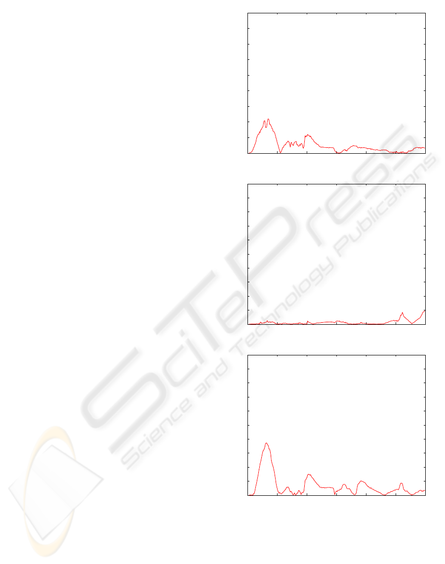
Figure 2 depicts the monocular tracker errors as-
sociated with a 300-frame long sequence which con-
tains rotational and translational out-of-plane head
motions. The nominal absolute depth of the head was
about 65 cm, and the focal length of the camera was
824 pixels. As can be seen, the out-of-plane motion
errors can be large for some frames for which there
is a room for improvement. Moreover, this evalua-
tion has confirmed the general trend of appearance-
based trackers, that is, the out-of-plane motion para-
meters (pitch angle, yaw angle, and depth) are more
affected by errors than the other parameters. More de-
tails about accuracy evaluation can be found in (Dor-
naika and Sappa, 2005).
One expects that the monocular tracker accuracy
can be improved if an additional cue is used. In our
case, the additional cue will be the 3D data associ-
ated with the mesh vertices provided by stereo recon-
struction. Although the use of stereo data may seem
as an excess requirement, recall that cheap and com-
pact stereo systems are now widely available (e.g.,
[www.ptgrey.com]).
We point out that there is no need to refine the facial
feature motions obtained by the above appearance-
based tracker since their independent motion can be
accurately recovered. Indeed, these features (the lips
and the eyebrows) have different textures, so their in-
dependent motion can be accurately recovered by the
appearance-based tracker.
6 IMPROVING THE 3D HEAD
POSE
The improved 3D face tracker is outlined in Figure 3.
The remainder of this section describes the improve-
ment steps based on sparse stereo-based 3D data.
Since the monocular tracker provides the 3D head
pose by matching the input texture with the adap-
0 50 100 150 200 250 30
0
0
10
20
30
40
50
60
70
80
90
Frames
Error (Deg.)
Yaw
0 50 100 150 200 250 30
0
0
2
4
6
8
10
12
14
16
18
20
Frames
Error (Cm)
Y Translation
0 50 100 150 200 250 300
0
2
4
6
8
10
12
14
16
18
20
Frames
Error (Cm)
Z Translation
Figure 2: 3D head pose errors computed by the ICP algo-
rithm associated with a 300-frame long sequence.
tive facial texture model (both textures correspond to
a 2D mesh), it follows that the out-of-plane motion
parameters can be inaccurate even when most of the
facial features project onto their true location in the
image. We use this fact to argue that the appearance-
IMPROVING APPEARANCE-BASED 3D FACE TRACKING USING SPARSE STEREO DATA
313
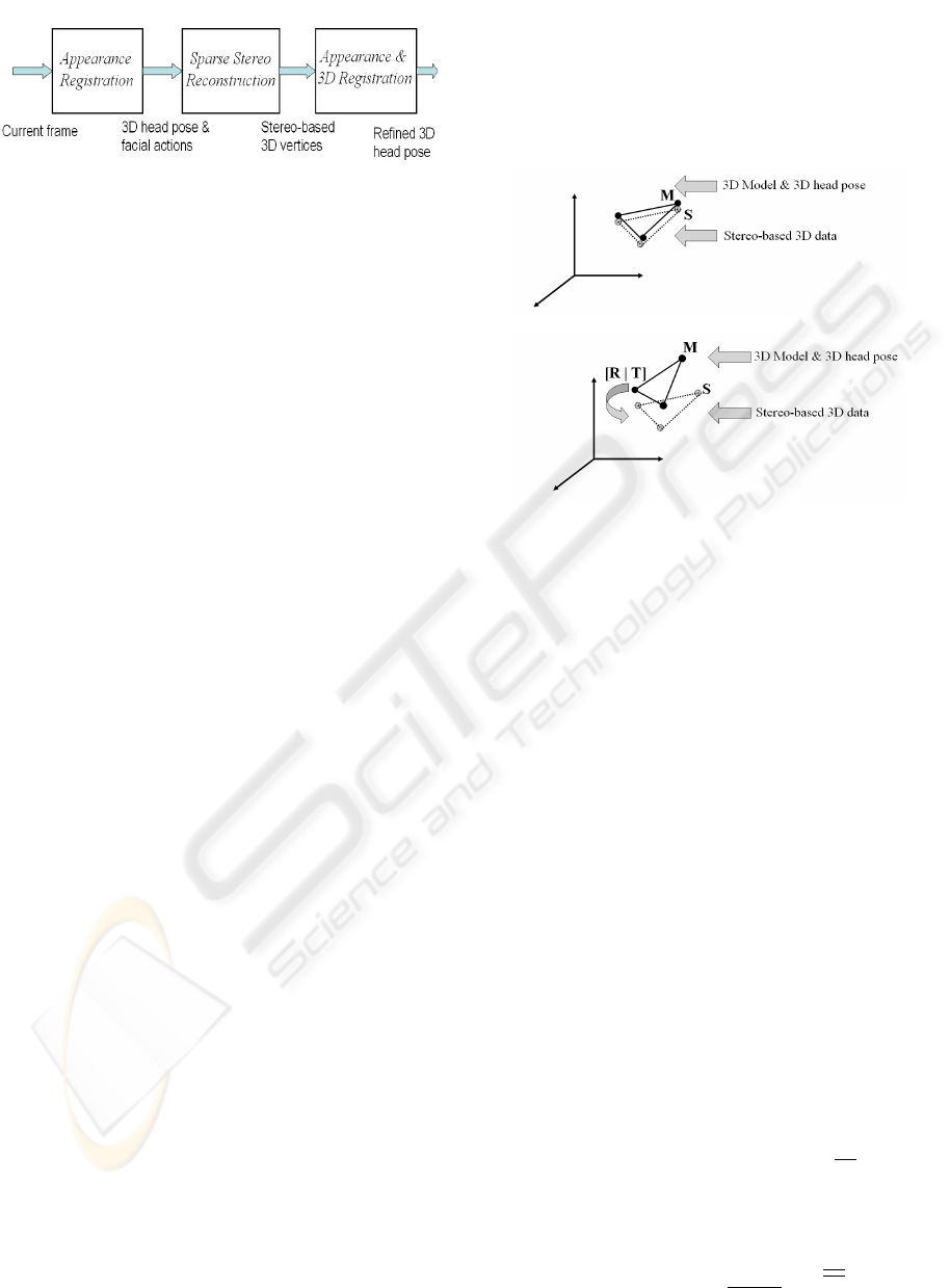
Figure 3: The main steps of the developed robust 3D face
tracker.
based tracker will greatly help in the sense that it will
provide the putative set of 3D-to-3D correspondences
through the 2D projections. Our basic idea is to start
from the 3D head pose provided by the monocular
tracker and then improve it by using some sparse 3D
data provided by stereo reconstruction. Here we use
the estimated six degrees of freedom as well as the
corresponding projection of all vertices. The esti-
mated 3D head pose will be used for mapping the 3D
mesh in 3D space while the 2D projections of the ver-
tices will be processed by the stereo system in order
to get their 3D coordinates.
Improving the 3D head pose is then carried out
by combining a robust 3D-to-3D registration and the
appearance model. The robust 3D registration uses
the 3D mesh vertices (the 3D model is mapped with
the estimated 3D head pose) and the corresponding
3D coordinates provided by the stereo rig while the
appearance model is always given by (10). Recall
that the stereo reconstruction only concerns the image
points resulting from projecting the 3D mesh vertices
onto the image. Since our 3D mesh contains about
one hundred vertices the whole refinement step will
be fast.
Figure 4 illustrates the basic idea that is behind the
improvement step, namely the robust 3D registration.
Figure 4 (Top) illustrates an ideal case where the esti-
mated appearance-based 3D head pose corresponds to
the true 3D pose. In this case, the vertices of the 3D
mesh after motion compensation coincide with their
corresponding 3D points provided by the stereo rig.
Figure 4 (Bottom) illustrates a real case where the
estimated appearance-based 3D head pose does not
correspond exactly to the true one. In this case, the
improvement can be estimated by recovering the 3D
rigid displacement [R|T] between the two sets of ver-
tices.
We point out that the set of vertex pairs may con-
tain some outliers caused for instance by occluded
vertices. Thus, the 3D registration process must be
robust. Robust 3D registration methods have been
proposed in recent literature (e.g., see (Chetverikov
et al., 2005; Fitzgibbon, 2003)). In our work, we use
a RANSAC-like technique that computes an adaptive
threshold for outlier detection. The whole improve-
ment algorithm is outlined in Figure 5. As can be
seen, the final solution (see the second paragraph in
Figure 5) takes into account two criteria: i) the 3D-
to-3D registration, and ii) the adaptive appearance
model.
Figure 4: (M) A 3D facial patch model positioned using
the estimated 3D head pose. (S) the same 3D patch (three
vertices) provided by stereo reconstruction. Top: An ideal
case where the appearance-based 3D head pose corresponds
to the true 3D head pose. Bottom: A real case where
the appearance-based 3D head pose does not exactly cor-
respond to the true 3D head pose. It follows that the im-
provement is simply the rigid 3D displacement [R|T] that
aligns the two sets of vertices.
Inlier detection. The question now is: Given a sub-
sample k and its associated solution D
k
, How do we
decide whether or not an arbitrary vertex is an inlier?
In techniques dealing with 2D geometrical features
(points and lines) (Fischler and Bolles, 1981), this
is achieved using the distance in the image plane be-
tween the actual location of the feature and its mapped
location. If this distance is below a given thresh-
old then this feature is considered as an inlier; oth-
erwise, it is considered as an outlier. Here we can
do the same by manually defining a distance in 3D
space. However, this fixed selected threshold cannot
accommodate all cases and all noises. Therefore, we
use an adaptive threshold distance that is computed
from the residual errors associated with all subsam-
ples. Our idea is to compute a robust estimation of
standard deviation of the residual errors. In the ex-
ploration step, for each subsample k, the median of
residuals was computed. If we denote by
M the least
median among all K medians, then a robust estima-
tion of the standard deviation of the residuals is given
by (Rousseeuw and Leroy, 1987):
ˆσ =1.4826
1+
5
N − 3
M (11)
VISAPP 2006 - MOTION, TRACKING AND STEREO VISION
314

where N is the number of vertices. Once ˆσ is known,
any vertex j can be considered as an inlier if its resid-
ual error satisfies |r
j
| < 3ˆσ.
Computational cost. On a 3.2 GHz PC, a non-
optimized C code of the robust 3D-to-3D registration
takes on average 15 ms assuming that the number of
random samples K is set to 20 and the total number
of the 3D mesh vertices, N , is 113. This compu-
tational time includes both the stereo reconstruction
and the robust technique outlined in Figure 5. Thus,
by appending the robust 3D-to-3D registration to the
appearance-based tracker (described before) a video
frame can be processed in about 70 ms.
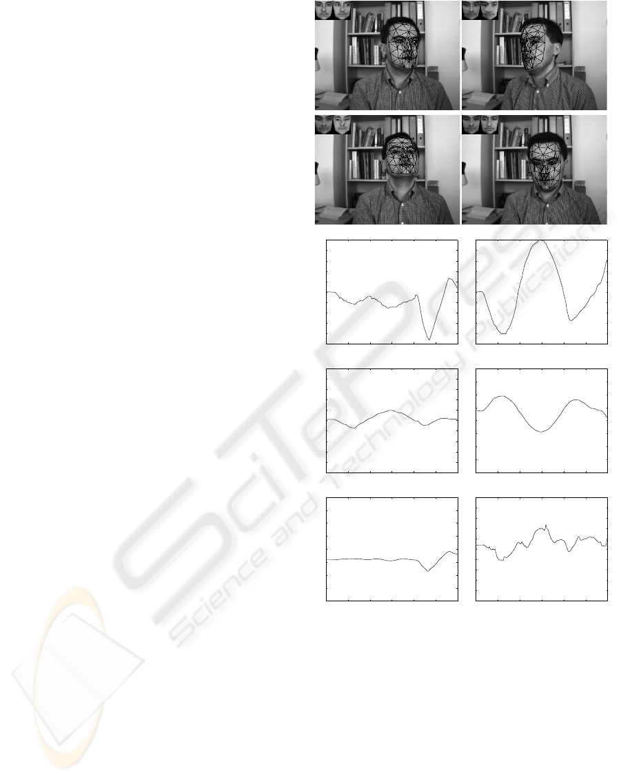
7 EXPERIMENTAL RESULTS
Figure 6 displays the head and facial action track-
ing results associated with a 300-frame-long sequence
(only four frames are shown). The tracking re-
sults were obtained using the adaptive appearance de-
scribed in Sections 4. The upper left corner of each
image shows the current appearance (µ
t
) and the cur-
rent shape-free texture (
ˆ
x
t
). In this sequence, the
nominal absolute depth of the head was about 80 cm.
As can be seen, the tracking results indicate good
alignment between the mesh model and the images.
However, it is very difficult to evaluate the accuracy of
the out-of-plane motions by only inspecting the pro-
jection of the 3D wireframe onto these 2D images.
Therefore, we have used ground truth data for the
3D head pose parameters associated with a video se-
quence similar to the one shown Figure 6. The ground
truth data are recovered by means of 3D registra-
tion between dense 3D facial clouds using the Iter-
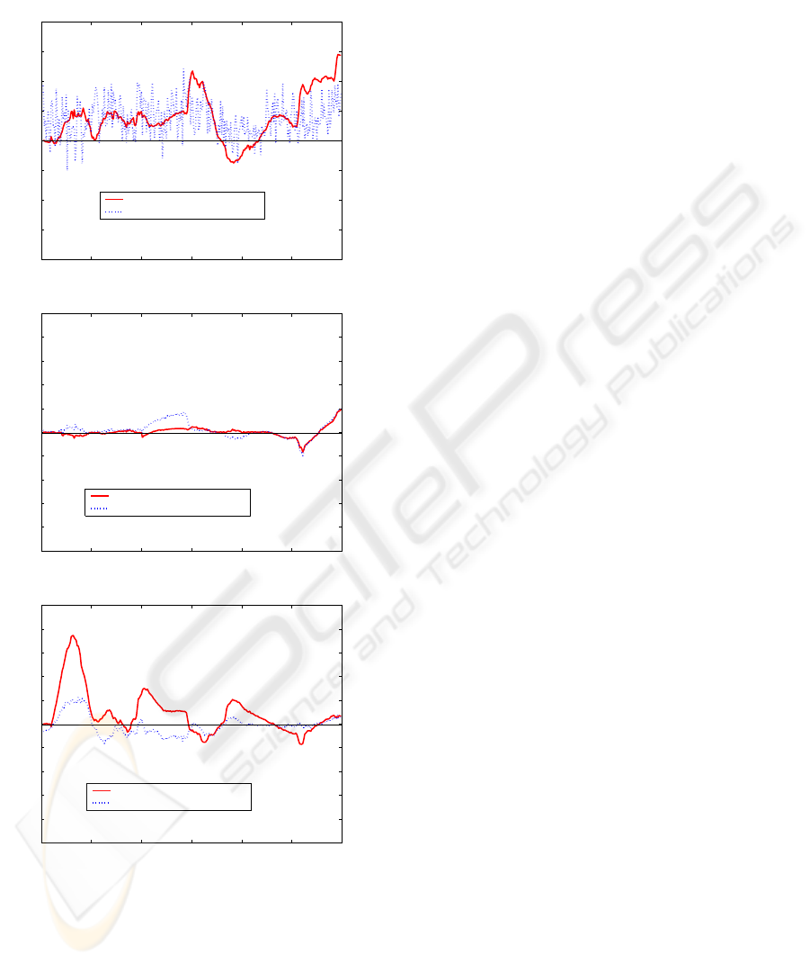
ative Closest Point algorithm. Figure 7 displays an
accuracy comparison between the appearance-based
tacker and the improved tracker using ground-truth
data. The solid curves correspond to the errors ob-
tained with the appearance-based tracker, and the
dashed ones correspond to those obtained with the de-
veloped approach including the robust 3D-to-3D reg-
istration technique. The top plot corresponds to the
pitch angle, the middle plot to the vertical translation,
and the bottom plot to the in-depth translation. As
can be seen, the most significant improvement affects
the in-depth translation. The noisy value of the pitch
angle error could be explained by the fact the 3D ro-
tation (improvement) is estimated from a small set of
3D points. However, on average the value of the ob-
tained error is equal to or less than the error obtained
with the appearance-based tracker.
Random sampling: Repeat the following three steps
K times
1. Draw a random subsample of 3 different pairs of
vertices. We have three pairs of 3D points {M
i
↔
S
i
},i=1, 2, 3.
2. For this subsample, indexed by k (k =1,...,K),
compute the 3D rigid displacement D
k
=[R
k
|T
k
],
where R
k
is a 3D rotation and T
k
a 3D translation,
that brings these three pairs into alignment. R
k
and
T
k
are computed by minimizing the residual error
3
i=1
|S
i
−R
k
M
i
−T
k
|
2
. This is carried out using
the quaternion method (Horn, 1987).
3. For this solution D
k
, compute the median M
k
of the squared residual errors with respect to the
whole set of N vertices. Note that we have N
residuals corresponding to all vertices {M
j
↔
S
j
},j=1,...,N. The squared residual associ-
ated with an arbitrary vertex M
j
is |S
j
− R
k
M
j
−
T
k
|
2
.
Solution:
1. For each solution D
k
=[R
k
|T
k
],k =1,...,K,
compute the number of inliers among the entire set
of vertices (see text). Let n
k
be this number.
2. Select the 10 best solutions, i.e. the solutions that
have the highest number of inliers.
3. Refine each such solution using all its inlier pairs.
4. For these 10 solutions, compute the corresponding
observation likelihood (5).
5. Choose the solution that has the largest observation
likelihood.
Figure 5: Recovering the 3D rigid displacement using ro-
bust statistics and the appearance.
8 CONCLUSION
In this paper, we have proposed a robust 3D
face tracker that combines the advantages of both
appearance-based trackers and 3D data-based track-
ers while keeping the CPU time very close to that
required by real-time trackers. Experiments on real
video sequences indicate that the estimates of the out-
of-plane motions of the head can be considerably im-
proved by combining a robust 3D-to-3D registration
with the appearance model.
REFERENCES
Ahlberg, J. (2002). An active model for facial feature track-
ing. EURASIP Journal on Applied Signal Processing,
2002(6):566–571.
IMPROVING APPEARANCE-BASED 3D FACE TRACKING USING SPARSE STEREO DATA
315
Besl, P. and McKay, N. (1992). A method for registration
of 3-D shapes. IEEE Transactions on Pattern Analysis
and Machine Intelligence, 14(2):239–256.
Cascia, M., Sclaroff, S., and Athitsos, V. (2000). Fast, re-
liable head tracking under varying illumination: An
approach based on registration of texture-mapped 3D
models. IEEE Transactions on Pattern Analysis and
Machine Intelligence, 22(4):322–336.
Chetverikov, D., Stepanov, D., and Kresk, P. (2005). Robust
Euclidean alignment of 3D point sets: the trimmed it-
erative closet point algorithm. Image and Vision Com-
puting, 23:299–309.
Cootes, T., Edwards, G., and Taylor, C. (2001). Active
appearance models. IEEE Transactions on Pattern
Analysis and Machine Intelligence, 23(6):681–684.
Dornaika, F. and Davoine, F. (2004). Head and facial anima-
tion tracking using appearance-adaptive models and
particle filters. In IEEE Workshop on Real-Time Vision
for Human-Computer Interaction, Washington DC.
Dornaika, F. and Sappa, A. (2005). Appearance-based
tracker: An evaluation study. In IEEE International
Workshop on Visual Surveillance and Performance
Evaluation of Tracking and Surveillance.
Fischler, M. and Bolles, R. (1981). Random sample consen-
sus: A paradigm for model fitting with applications to
image analysis and automated cartography. Commu-
nication ACM, 24(6):381–395.
Fitzgibbon, A. (2003). Robust registration of 2D and 3D
point sets. Image and Vision Computing, 21:1145–
1153.
Horn, B. (1987). Closed-form solution of absolute orien-
tation using unit quaternions. J. Opt. Soc. Amer. A.,
4(4):629–642.
Jepson, A., Fleet, D., and El-Maraghi, T. (2003). Robust
online appearance models for visual tracking. IEEE
Transactions on Pattern Analysis and Machine Intel-
ligence, 25(10):1296–1311.
Lee, D. (2005). Effective Gaussian mixture learning
for video background subtraction. IEEE Transac-
tions on Pattern Analysis and Machine Intelligence,
27(5):827–832.
Malassiotis, S. and Strintzis, M. G. (2005). Robust real-
time 3D head pose estimation from range data. Pattern
Recognition, 38(8):1153–1165.
Matthews, I. and Baker, S. (2004). Active appearance mod-
els revisited. International Journal of Computer Vi-
sion, 60(2):135–164.
Moreno, F., Tarrida, A., Andrade-Cetto, J., and Sanfeliu, A.
(2002). 3D real-time tracking fusing color histograms
and stereovision. In IEEE International Conference
on Pattern Recognition.
Rousseeuw, P. and Leroy, A. (1987). Robust Regression and
Outlier Detection. John Wiley & Sons, New York.
Zhou, S., Chellappa, R., and Mogghaddam, B. (2004).
Visual tracking and recognition using appearance-
adaptive models in particle filters. IEEE Transactions
on Image Processing, 13(11):1473–1490.
0 50 100 150 200 250 30
0
−50
−40
−30
−20
−10
0
10
20
30
40
50
Frames
Deg.
Pitch
0 50 100 150 200 250 30
0
−50
−40
−30
−20
−10
0
10
20
30
40
50
Frames
Deg.
Yaw
0 50 100 150 200 250 30
0
−50
−40
−30
−20
−10
0
10
20
30
40
50
Frames
Deg.
Roll
0 50 100 150 200 250 30
0
−20
−15
−10
−5
0
5
10
15
20
Frames
Cm
X Translation
0 50 100 150 200 250 300
−20
−15
−10
−5
0
5
10
15
20
Frames
Cm
Y Translation
0 50 100 150 200 250 300
50
55
60
65
70
75
80
85
90
95
100
Frames
Cm
Z Translation
Figure 6: Tracking the 3D head pose with appearance-based
tracker. The sequence length is 300 frames. Only frames
38, 167, 247, and 283 are shown. The six plots display the
six degrees of freedom of the 3D head pose as a function of
time.
VISAPP 2006 - MOTION, TRACKING AND STEREO VISION
316
0 50 100 150 200 250 30
0
−20
−15
−10
−5
0
5
10
15
20
Frames
Error (Deg.)
Pitch
Appearance−based tracker
Improved tracker
0 50 100 150 200 250 30
0
−10
−8
−6
−4
−2
0
2
4
6
8
10
Frames
Error (cm)
Y Translation
Appearance−based tracker
Improved tracker
0 50 100 150 200 250 300
−10
−8
−6
−4
−2
0
2
4
6
8
10
Frames
Error (cm)
Z Translation
Appearance−based tracker
Improved tracker
Figure 7: 3D head pose errors associated with the sequence
as a function of the frames. From top to bottom: pitch an-
gle error, vertical translation error, and in-depth translation
error. The solid curves display the errors obtained with the
appearance-based tracker, and the dashed ones display those
obtained with the improved tracker.
IMPROVING APPEARANCE-BASED 3D FACE TRACKING USING SPARSE STEREO DATA
317
