
REAL-TIME TRACKING FOR VIRTUAL ENVIRONMENTS USING
SCAAT KALMAN FILTERING AND UNSYNCHRONISED CAMERAS
Niels Tjørnly Rasmussen
Image House A/S
St. Kannikestraede 7, DK-1169 Copenhagen, Denmark
Moritz St
¨
orring, Thomas B. Moeslund, and Erik Granum
Department for Media Technology and Engineering Science, Aalborg University
Niels Jernes Vej 14, DK-9220 Aalborg, Denmark
Keywords:
Pose Estimation, Tracking, SCAAT Extended Kalman Filter, Stereo Triangulation.
Abstract:
This paper presents a real-time outside-in camera-based tracking system for wireless 3D pose tracking of
a user’s head and hand in a virtual environment. The system uses four unsynchronised cameras as sensors
and passive retroreflective markers arranged in rigid bodies as targets. In order to achieve high update rates
and to cope with the unsynchronised data a single-constraint-at-a-time (SCAAT) Extended Kalman Filtering
approach is used that recursively integrates measurements as soon as they are available one-at-a-time. Tests
show that this approach is more robust to occlusions and provides less noisy pose estimates with a higher
update rate than a conventional stereo triangulation approach.
1 INTRODUCTION
A crucial part in virtual environments (VEs) is the
real-time tracking of the 3D position and orientation –
six degree-of-freedom (DOF) pose – of a user’s head
and hand(s). Most importantly, the pose of a user’s
head is needed for the correct computation of stereo-
scopic images, which create the illusion of a three-
dimensional virtual world, displayed in the VE.
A set of requirements for VE interaction de-
vices are summarised as follows: wireless, pre-
cise/accurate, high resolution, lightweight, quick re-
sponse time/low latency, and 6 DOF (Stefani et al.,
2003). In a study of locomotion principles in VEs,
(Usoh et al., 1999) have identified wires as a signifi-
cant problem causing “breaks-in-presence” and state
that wireless tracking is the most needed system im-
provement for VEs.
Current tracking technology utilises many differ-
ent physical principles: mechanical, inertial, acousti-
cal, magnetic, optical, and radio frequency (Bhatna-
gar, 1993; Ferrin, 1991; Holloway and Lastra, 1993;
Madritsch, 1996; Meyer et al., 1992; Mulder, 1994;
Ribo, 2001; Rolland et al., 2001; Welch and Foxlin,
2002; Youngblut et al., 1996). Each of these have
their strengths and weaknesses, see (Youngblut et al.,
1996). Many of the existing tracking systems fulfil the
requirements of precise and high resolution 6 DOF
tracking. However, these are usually either tethered to
the user by wires, unsuitable for fully immersive VEs
due to size of sensors or quiet expensive. (Madritsch,
1996; Meyer et al., 1992; Rolland et al., 2001; Welch
and Foxlin, 2002; Youngblut et al., 1996)
A typical categorisation of tracking systems is the
distinction between
inside-out
– where sensors are
placed on the target viewing references, e.g., beacons,
usually fixed in the environment – and
outside-in
–
where sensors are mounted at fixed places in the en-
vironment viewing references, e.g., markers, on the
target – tracking. (Bhatnagar, 1993; Holloway and
Lastra, 1993; Madritsch, 1996; Meyer et al., 1992;
Mulder, 1994; Ribo, 2001; Rolland et al., 2001)
Among the available technologies optical track-
ing is the most promising for constructing a wire-
less, accurate, high update rate and low latency track-
ing system. However, due to problems with unsyn-
chronised cameras and video interlacing current state-
of-the-art optical tracking systems are based on spe-
cial hardware that is expensive and comes with large
cameras that are not suitable for closed VEs such
as the CAVE (Fig. 1). Whereas systems based on
using small of the shelf cameras only achieve poor
tracking performance compared to the most com-
monly used magnetic tracker for VEs, the Polhemus
FASTRAK
®
, e.g., (Chung et al., 2001; Dorfm
¨
uller,
1999a; Dorfm
¨
uller and Wirth, 1998; Gennery, 1992;
Madritsch, 1996; Madritsch and Gervautz, 1996;
Ribo et al., 2001; Ribo, 2001; Welch et al., 2001)
333
Tjørnly Rasmussen N., Störring M., B. Moeslund T. and Granum E. (2006).
REAL-TIME TRACKING FOR VIRTUAL ENVIRONMENTS USING SCAAT KALMAN FILTERING AND UNSYNCHRONISED CAMERAS.
In Proceedings of the First International Conference on Computer Vision Theory and Applications, pages 333-340
DOI: 10.5220/0001367803330340
Copyright
c
SciTePress

The problem of unsynchronised cameras is related
to the use of conventional methods, such as stereo tri-
angulation, which are based on the simultaneity as-
sumption i.e. the assumption that measurements from
two or more cameras are collected simultaneously.
This simultaneity assumption introduces an error in
the pose estimates of the tracker if the target(s) is
moving. (Welch, 1996; Welch and Bishop, 1997)
In this paper a new real-time outside-in camera-
based tracking system for wireless 6 DOF pose track-
ing is presented. The tracking system uses four un-
synchronised small surveillance cameras as sensors
and passive retroreflective markers arranged in rigid
bodies as targets. Two approaches are examined: a
conventional approach using stereo triangulation, and
a recursive approach using single-constraint-at-a-time
Extended Kalman Filtering (SCAAT-EKF) (Welch,
1996; Welch and Bishop, 1997).
Results show that the optical tracker using the
SCAAT-EKF approach is not only superior to the
stereo triangulation approach, but also has a compa-
rable performance to the commonly used Polhemus
FASTRAK
®
magnetic tracker (Holloway and Lastra,
1993) with a static RMS accuracy of 1 mm and 0.5
◦
,
a dynamic RMS accuracy of 2 mm and 1
◦
, a latency
of approx. 21 ms, and an update rate of 200 Hz within
a working volume of 2.5 m × 2.5 m × 2.5 m.
This paper is organised as follows: Sect. 2 presents
related work. A brief description of the tracking sys-
tem is given in Sect. 3. Experimental results for the
tracking system are presented in Sect. 4, which is fol-
lowed by a discussion and conclusions in Sect. 5.
2 RELATED WORK
This section gives a brief overview of some impor-
tant research examples of optical tracking systems.
For an overview of existing commercial systems see
(Ribo, 2001; Youngblut et al., 1996). For a detailed
overview of current optical tracking technology see
(Rasmussen, 2003).
Systems using conventional approaches – such
as epipolar geometry and stereo triangulation –
are presented in (Chung et al., 2001; Dorfm
¨
uller,
1999a; Dorfm
¨
uller and Wirth, 1998; Dorfm
¨
uller,
1999b; Madritsch and Gervautz, 1996; Ribo et al.,
2001). (Madritsch and Gervautz, 1996) introduces an
outside-in camera-based optical tracking system. The
system uses two CCD-cameras and red light emit-
ting LEDs or beacons. Due to the use of unsynchro-
nised cameras the estimated beacon positions are not
very precise when beacons are moving (Dorfm
¨
uller,
1999a). In (Dorfm
¨
uller and Wirth, 1998) a similar
outside-in system based on two synchronised CCD-
cameras and infrared LEDs is presented. The system
only tracks 3 DOF at an accuracy of ≈ 2 cm, which
is due to imprecise calibration and down-sampling
of images. (Dorfm
¨
uller, 1999a; Dorfm
¨
uller, 1999b)
presents a further development of this system using
synchronised progressive scan cameras and retrore-
flective markers. 6 DOF tracking is added using rigid
bodies and the accuracy is reported to be ≈ 6 mm.
(Ribo et al., 2001) presents a similar system capable
of tracking up to 25 markers at 30 Hz. No quantita-
tive accuracy results are given. Finally, (Chung et al.,
2001) describes a system using four CCD-cameras
and large retroreflective markers. The 3D position
data are jittery and are estimated at a rate of 15 Hz.
Recursive approaches for tracking, e.g., Kalman fil-
tering, are presented in (Gennery, 1992; Welch et al.,
2001). (Gennery, 1992) presents an outside-in track-
ing system capable of tracking a known 3D object
with 6 DOF. The method uses the predicted posi-
tion of known features on the object to find the fea-
tures in images from one or more cameras, measures
the position of the features in the images, and uses
these measurements to update the estimates of posi-
tion, orientation, linear velocity, and angular veloc-
ity of the object model. The solution is a Kalman
filter like weighted least-squares adjustment, which
allows the use of multiple unsynchronised measure-
ments. (Welch et al., 2001) presents the inside-out Hi-
Ball tracking system, which has been commercialised
by 3rdTech
™
. The system uses a sensing unit called
the HiBall, which is fixed to the target being tracked.
The HiBall unit observes infrared LEDs mounted in
the ceiling through multiple sensor-lens views that
are distributed over a large solid angle. LEDs are se-
quentially flashed (one at a time). Initial acquisition
is performed using a brute force search through LED
space. Tracking is performed using the SCAAT-EKF
approach (Welch and Bishop, 1997; Welch, 1996).
The crux of the SCAAT-EKF approach is that the
state of the estimated system, i.e., the HiBall pose,
is updated for each measurement (2D image coor-
dinate) even though this only provides partial or in-
complete information of the system state. Complete
information of the system state is obtained by incre-
mentally fusing measurements from different sensors
over time. Using this approach, measurements are
applied when obtained, yielding more frequent esti-
mates (2000 Hz), less latency (1 ms), and improved
accuracy (0.5 mm linear and 0.02
◦
angular).
In this paper two approaches to optical tracking for
an outside-in system using unsynchronised cameras
are explored: a conventional approach using stereo
triangulation, and a SCAAT-EKF approach based on
(Welch and Bishop, 1997; Welch, 1996; Welch et al.,
2001) and (Gennery, 1992). The latter approach ef-
fectively integrates measurements as soon as they are
available from each of the unsynchronised cameras
one-at-a-time, thereby avoiding the erroneous simul-
VISAPP 2006 - MOTION, TRACKING AND STEREO VISION
334
User
Rigid body
head
Rigid body
hand
X
w
Y
w
Z
w
Camera 1
Camera 4
Camera 2
Camera 3
IR-LEDs
2.5 m
Retroreflective
markers
IR-filters
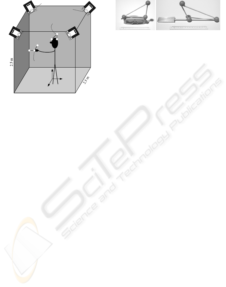
Figure 1: Optical tracking system setup.
taneity assumption.
3 THE TRACKING SYSTEM
This section gives an overview of the developed op-
tical tracking system. For details readers are referred
to (Rasmussen, 2003).
3.1 Setup
The optical tracking system consists of a fully cal-
ibrated setup of four unsynchronised CCD-cameras
(Monacor TVCCD-140IR, f =3.6 mm) mounted in
the top four corners of a CAVE, Fig. 1. Tracked ob-
jects are fitted with retroreflective markers (30 mm
spheres) arranged in a rigid body, Fig. 2. These
markers reflect the infrared light emitted by IR-LEDs
built-in the monochrome CCIR cameras, which have
been fitted with infrared pass filters (Kodak Wratten
#87). The cameras are connected to a frame grabber
(Coreco Viper-Quad) in a dual Pentium
®
III 800 MHz
PC. To avoid errors from interlacing video capturing
is performed using notification of field updates in full
frame images.
Camera calibration has been performed using the
MATLAB
®
Camera Calibration Toolbox (Bouguet,
2002) with a custom-made checkerboard pattern by
1) calibrating the intrinsic parameters for each cam-
era individually, and 2) calibrating the extrinsic pa-
rameters of all four cameras based on the manually
measured position of the checkerboard in the CAVE.
For details see (Rasmussen, 2003).
Two different rigid bodies RB
head
and RB
hand
,
Figure 2: Rigid bodies: RB
head
and RB
hand
.
Fig. 2, have been constructed for head and hand track-
ing, respectively.
3.2 Marker Localisation
Marker positions are determined by 1) segmenting
the image into background and marker blobs us-
ing a simple global threshold, and 2) calculating the
weighted centre of mass of each marker blob. When
the SCAAT-EKF approach is used, predicted marker
positions are used to speed up segmentation by lo-
cal searching and to determine correspondence using
a modified greedy algorithm (Rangarajan and Shah,
1991).
3.3 Stereo Triangulation
The stereo triangulation approach processes two sets
of 2D marker image positions from two different cam-
eras measured within a predefined time window (here
50 ms) and, then, matches triangulated 3D points to
the known structure of the rigid bodies using a brute
force greedy 3D point set pattern matching algorithm.
The 3D poses of the rigid bodies are estimated from
the corresponded marker 3D measurements by a sim-
ple and fast closed-form three point algorithm de-
scribed in (Horn, 1987). Fig. 3 depicts the steps of
the stereo triangulation approach.
3.4 SCAAT-EKF
The SCAAT-EKF approach employs a SCAAT Ex-
tended Kalman Filter for each of the tracked rigid
bodies. The filters encapsulate the state (e.g. 3D pose)
and process model of the rigid bodies and the mea-
surement model of the cameras.
State & process model: The dynamics or motion of
the rigid bodies is modelled by the process model.
As in (Welch, 1996; Welch and Bishop, 1997) a sim-
ple position-velocity (PV) model is used. The state
of the SCAAT-EKF, thus, contains both the position
and orientation, and the linear and angular velocities
of the rigid body. In practice the orientation is main-
tained as a combination of a global, external quater-
nion and a set of internal, incremental angles, as de-
scribed in (Gennery, 1992; Welch, 1996; Welch and
Bishop, 1997).
REAL-TIME TRACKING FOR VIRTUAL ENVIRONMENTS USING SCAAT KALMAN FILTERING AND
UNSYNCHRONISED CAMERAS
335

Inverse
Mapping
3D Line
Matching
3D Point
Clustering
3D Point
Matching
3D Pose
Estimation
Z
w
X
w
Y
w
Measured 2D
marker positions
3D
lines
Triangulated
3D points
3D point
clusters
Corresponded
3D points
Rigid body
3D pose(s)
Camera
Models
Rigid Body
Model(s)
Figure 3: Steps of the stereo triangulation approach; First, 3D lines are computed using the camera models. 3D lines are
then triangulated or matched by discarding line pairs that do not intersect within a given distance. Next, triangulated 3D
positions are grouped into clusters based on the assumption that rigid bodies are separated by a minimum distance larger than
the maximum distance between two markers in any of the rigid bodies. Clusters are then matched against the rigid bodies
using the distances between the 3D positions in the clusters to match against the known distances between markers in each of
the rigid bodies. Finally, the corresponded, measured 3D positions of the rigid body markers are used to compute the 3D pose
of each of the rigid bodies.
In addition, the process model is characterised by
a set of process noise parameters (one for each of the
six position and orientation elements) describing the
magnitude of the (assumed constant) noise sources
presumed to be driving the process model. In this pa-
per a similar approach to the one presented in (Welch,
1996) is used, where the values are tuned in a sim-
ulation environment to different dynamics using real
motion data based on an overall cost function for a
given motion data set (Rasmussen, 2003).
Measurement model: The measurement model is
used to predict the ideal noise-free response of a cam-
era, given the filter’s current estimate of the rigid body
state and the
a priori
rigid body model. In this pa-
per, the measurement model is defined by the camera
model determined by the off-line camera calibration.
As this model is non-linear the Jacobian is needed in
the EKF. For details see (Rasmussen, 2003). Further-
more, the SCAAT-EKF needs an estimate of the noise
in the actual measurements. This is determined in
real-time based on a model estimated from off-line
measurements of marker image positions and marker
blob areas.
Algorithm: The algorithm for recursive tracking us-
ing SCAAT-EKF operates in a loop of four steps, see
Fig. 4. The loop is entered after tracking is initialised
using the stereo triangulation approach:
Prediction: Whenever an image (field) is acquired by
one of the cameras, it is time stamped, and the previ-
ous rigid body state(s) are extrapolated to this time.
Projection: The 2D marker image positions are com-
puted from the predicted rigid body pose(s), rigid
body model(s) and the camera model of the current
camera.
Measurement: The predicted image positions are then
used to compute the measured marker image positions
with correspondence.
Correction: Whenever a set of measured marker im-
age positions with correspondence has been com-
puted, the SCAAT-EKFs are updated i.e. for each of
the individually measured positions the correspond-
ing SCAAT-EKF is corrected using the SCAAT algo-
rithm described in (Welch and Bishop, 1997).
4 RESULTS
This section presents test results of the implemented
optical tracking system in a CAVE. The test of the
system has been conducted as a comparison of the
two tracking approaches: stereo triangulation and
SCAAT-EKF.
In every real world test an important factor is the
acquisition of ground truth data, as this inherently de-
fines the degree to which a test is significant. For the
implemented prototype ground truth data must have
submillimeter positional and subdegree rotational ac-
curacy in order to be applicable for the tests. As this
sort of accuracy is not readily available the tests con-
ducted here are relative, i.e., data is acquired under
specific conditions, e.g., only planar translation, and
then correspondingly fitted to these. The relative er-
ror w.r.t. the fit can then be computed and used as
an indication of the prototype performance. For com-
parability and simplicity the accuracy test results pre-
sented here will only be given for tracking a single
rigid body, the RB
head
(rigid body head).
4.1 Error Measures
Two error measures are used:
Overall RMS error (β
RMS
) is the normalised root-
mean-square error of a dataset with regard to the fit
in question e.g. the distance of a measured position to
a plane fitted to the data set, d
p,RMS
.
Overall peak error (β
max
) or overall max error is the
largest absolute error of a dataset with regard to the
VISAPP 2006 - MOTION, TRACKING AND STEREO VISION
336

Prediction Projection
MeasurementCorrection
Predicted rigid body
3D pose(s)
Predicted marker 2D
image positions
Measured marker
2D image positions
Image
timestamp
Corrected rigid
body 3D pose(s)
Track initialized
Output
Image
Rigid body model(s)
Camera model
Figure 4: SCAAT-EKF loop: Solid arrows: program flow and data; dashed arrows: data only. Based on (Gennery, 1992).
fit e.g. the maximum distance between a measured
position and the mean position of the data set, d
max
.
4.2 Static Test
The static test shows the performance of the two
tracking approaches when the rigid body is static i.e.
not moving.
Setup: The rigid body was mounted on a steady
metal rack and placed in a grid at 9 different posi-
tions in two planes at different heights. 2000 sam-
ples of the position and orientation of the rigid body
were then recorded for both the stereo triangula-
tion and the SCAAT-EKF approach for each position.
For SCAAT-EKF process noise parameters were used
suitable for low dynamic motion.
Grid test: The grid test measures the overall distance
error d from the mean grid positions and the over-
all orientation error α from the mean orientation an-
gles. Table 1 lists the results for the stereo triangu-
lation and the SCAAT-EKF approach. These results
clearly show the superiority of the SCAAT-EKF ap-
proach with an RMS position error 20 times smaller
and an RMS orientation error 7 times smaller than
the stereo triangulation approach. The high peak er-
rors for stereo triangulation are possibly due to false
model-matching.
Plane test: The plane test is based on the assump-
tion that the CAVE floor is flat and smooth. A plane
has, thus, been fitted to the two grid sets (*,*,0) and
(*,*,1) for each of the two approaches. Table 2 lists
the plane fit results for both the stereo triangulation
and the SCAAT-EKF approach. The plane fit error is
given by the overall RMS and overall peak distance
d
p
of the measured rigid body positions to the plane.
Again the results are in favour of the SCAAT-EKF
approach; most significantly with regard to the peak
errors, which are 3-4 times smaller than for the stereo
triangulation approach.
Table 1: Stereo triangulation and SCAAT-EKF rigid body
pose test results for 3×3×2 static grid configuration, where
d is in [mm] and α is in [degree].
Position Orientation
Approach d
RMS
d
max
α
RMS
α
max
Stereo triang. 5.16 11.29 0.64 27.98
SCAAT-EKF 0.26 1.25 0.09 0.51
Table 2: Stereo triangulation and SCAAT-EKF rigid body
position plane fit test results, where d
p
is in [mm].
Plane error
Approach Index d
p,RMS
d
p,max
Stereo triang.
(*,*,0) 2.31 7.03
(*,*,1) 1.57 4.96
SCAAT-EKF
(*,*,0) 1.07 1.60
(*,*,1) 0.93 1.47
4.3 Dynamic Test
The aim of the dynamic test is to examine the per-
formance of the two tracking approaches when the
rigid body is moving. The test is based on the as-
sumption of perfect circular motion, which is easily
accomplished by attaching the rigid body to a rotat-
ing object.
Setup: The rigid body was attached to two differ-
ent turntables and 20,000 samples of the rigid body
position and orientation were recorded of both the
stereo triangulation and the SCAAT-EKF estimates.
For SCAAT-EKF a set of process noise parameters
suitable for high dynamic motion was used. The two
turntables are briefly described here:
Industrial turntable with a turning speed of 0.75
RPM, see Fig. 5. The rigid body was attached to a
simple wood construction to increase the radius of the
circular movement and, thus, increase the speed of the
rigid body.
HMV grammophone with three turning speeds: 33,
REAL-TIME TRACKING FOR VIRTUAL ENVIRONMENTS USING SCAAT KALMAN FILTERING AND
UNSYNCHRONISED CAMERAS
337
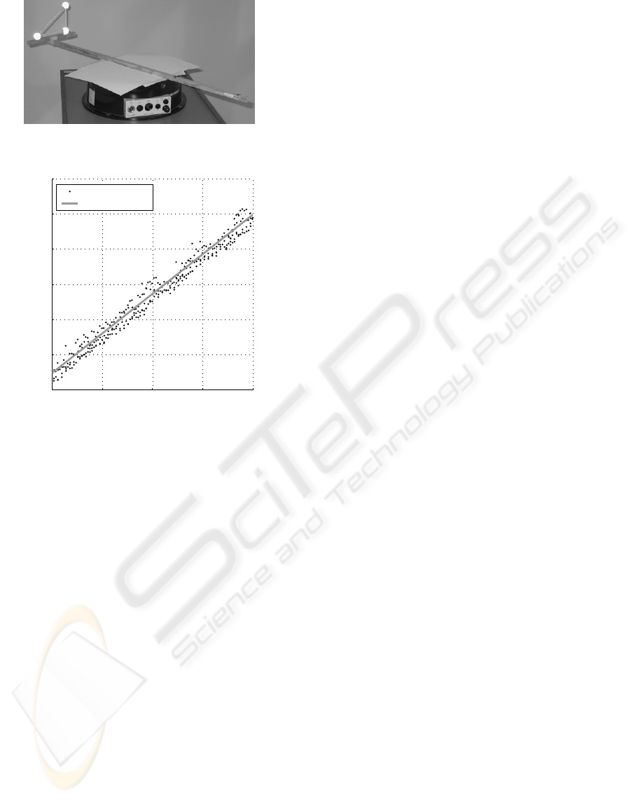
Figure 5: Industrial turntable used for the dynamic test.
55 55.5 56 56.5 5
7
94
96
98
100
102
104
106
Time [s]
ψ [degree]
Measurements
Line fit
Figure 6: Example of constant angular velocity line fit.
45, and 78 RPM.The rigid body was attached directly
to the turning disc.
3D circle test: Based on the assumption of perfect
circular motion a 3D circle was fitted to the rigid body
position samples of the four test cases for each of the
two tracking approaches. The corresponding overall
RMS and peak errors of the distance d
c
to the circle
were then computed and are listed in Tables 3 and 4,
where r
c
denotes the radius of the circle fit.
Constant angular velocity test: Assuming that the
rotation of the rigid body has constant velocity, the
reported ψ angle is linear w.r.t. time if the esti-
mates are not constrained within the normal range of
[−180
◦
, 180
◦
], but instead monotonically increase or
decrease from the initial start angle. Based on this
assumption a 2D line is fitted to the time vs. ψ data
(see Fig. 6) and the angular error ψ
e
is computed by
comparing the fitted line estimate for a given time to
the measured angle. The slope of the 2D line is, thus,
the estimated constant angular velocity
˙
ψ of the rigid
body. The corresponding overall RMS and peak er-
rors for each of the four test cases are listed in Ta-
bles 3 and 4 for stereo triangulation and SCAAT-EKF,
respectively.
The results of the dynamic test verify the superior-
ity of the SCAAT-EKF approach over the stereo tri-
angulation approach when the rigid body is moving.
In this case the violation of the simultaneity assump-
tion by the stereo triangulation approach not only
induces increased errors in the pose estimates, but
also leads to false model-matching, yielding very high
peak errors, as can easily be seen for the three HMV
turntable cases in Table 3. Although, these peak er-
ror outliers are rare they pinpoint exactly the strength
of the SCAAT-EKF approach, which not only effec-
tively suppresses outliers but also reduces the possi-
bility of false matching due to its predict-match be-
haviour, where actual measurements are matched as
soon as they are made to the predicted measurements
of the filter.
4.4 Robustness and Timing
Although, no rigorous and explicit test has been per-
formed of the SCAAT-EKF approach with regard to
robustness against occlusions and noise no real tests
have yet revealed severe problems. This has also been
confirmed by test results from MATLAB
®
simula-
tions using both the SCAAT-EKF and stereo triangu-
lation approaches on real motion data with simulated
occlusions and different levels of measurement noise
(Rasmussen, 2003). It should, however, be noted
that tracking robustness depends on the process noise
parameters used. If the parameters are too low the
tracker will lag behind and may lose track. If the pa-
rameters are too high the tracker estimates will be jit-
tery. For optimal performance it is crucial that process
noise parameters reflect the motion of the user.
Other important characteristics are the latency and
update rate of the reported pose estimates. The la-
tency of the tracker is the sum of the measurement
and computation latencies. The measurement latency
is 20 ms for the CCIR cameras. The computation la-
tency is dependent on the number of rigid bodies be-
ing tracked. For stereo triangulation it is 4.2 ms and
5.5 ms for tracking one and two rigid bodies, respec-
tively. The SCAAT-EKF approach has 0.5 ms and
0.9 ms. The total latency of the SCAAT-EKF ap-
proach tracking two rigid bodies is ≈ 21 ms.
For the stereo triangulation approach the update
rate is dependent on the number of cameras, which
have a clear view of all the rigid body markers. For
the SCAAT-EKF approach it is dependent on the
number of cameras, which have a clear view of just
a single or more rigid body markers. Thus, both have
an update rate of c · 50 Hz, where c is the number
of cameras. In almost all the test cases the SCAAT-
EKF approach had an update rate of 200 Hz, while the
stereo triangulation approach had an update rate in the
range from 100 Hz to 200 Hz, where full update rate
was only rarely obtained.
VISAPP 2006 - MOTION, TRACKING AND STEREO VISION
338

Table 3: Stereo triangulation rigid body dynamic test results, where r
c
denotes circle radius in [mm], d
c
denotes distance to
circle in [mm],
˙
ψ denotes angular velocity in [degree/s], and ψ
e
denotes angular error in [degree].
Turntable r
c
d
c,RMS
d
c,max
˙
ψψ
e,RMS
ψ
e,max
Industrial 500.85.14 11.21 4.50 0.44 1.91
HMV at 33 RPM 59.14.25 56.02 −201.09 2.03 47.09
HMV at 45 RPM 59.44.96 56.09 −272.12 1.88 45.72
HMV at 78 RPM 59.35.00 55.25 −467.76 3.97 50.29
Table 4: SCAAT-EKF rigid body dynamic test results, where r
c
denotes circle radius in [mm], d
c
denotes distance to circle
in [mm],
˙
ψ denotes angular velocity in [degree/s], and ψ
e
denotes angular error in [degree].
Turntable r
c
d
c,RMS
d
c,max
˙
ψψ
e,RMS
ψ
e,max
Industrial 501.01.67 4.47 4.50 0.45 1.38
HMV at 33 RPM 59.21.27 3.80 −201.22 0.99 3.11
HMV at 45 RPM 59.03.49 11.36 −272.18 0.83 2.93
HMV at 78 RPM 58.72.44 7.24 −467.52 1.99 4.93
5 CONCLUSIONS
A new real-time outside-in camera-based tracker sys-
tem has been presented. The system uses multiple un-
synchronised, cheap, infrared light emitting surveil-
lance cameras as sensors, and passive retroreflective
markers arranged in rigid bodies as targets.
Two approaches were examined in the system: a
conventional approach using stereo triangulation and
a recursive approach using SCAAT-EKF. While the
stereo triangulation approach is based on the assump-
tion that measurements from two cameras are ob-
tained simultaneously, the SCAAT-EKF approach re-
cursively integrates measurements as soon as they are
available one-at-a-time. This not only avoids errors
associated with the unsynchronised camera setup, but
also provides for higher update rate, lower latency,
noise reduction and prediction.
The results show that the SCAAT-EKF approach
gives less noisy and less jittery 3D pose estimates
with a higher update rate and lower latency than the
stereo triangulation approach. For example, static test
results show a total overall RMS distance error of
5.16 mm for the stereo triangulation approach, which
is about 20 times larger than the corresponding error
of 0.26 mm for the SCAAT-EKF approach. A similar
result is evident for the orientation with a total RMS
angular error of 0.64
◦
against 0.09
◦
.
Finally, results show that the implemented pro-
totype using SCAAT-EKF has a comparable perfor-
mance to the commonly used Polhemus FASTRAK
®
magnetic tracker (Holloway and Lastra, 1993) with
a static RMS accuracy of 1 mm and 0.5
◦
, a dynamic
RMS accuracy of 2 mm and 1
◦
, a latency of approx.
21 ms, and an update rate of 200 Hz within a working
volume of 2.5 m × 2.5 m × 2.5 m.
There are several possible improvements of the
tracking system, which should be investigated:
Autocalibration: It is possible to add autocalibra-
tion of the cameras in the SCAAT-EKF approach sim-
ilar to the beacon autocalibration in (Welch, 1996).
Adaptive or multiple-model filtering: As the ac-
tivities of a user in a VE range from standing com-
pletely still to fast head turning and arm swinging, the
static set of process noise parameters used for track-
ing might be replaced by a multiple-model or adap-
tive filtering approach, as discussed in (Welch, 1996,
Chap. 7).
Unscented Kalman filtering: In (Julier and
Uhlmann, 1997) and (Wan and Van Der Merwe,
2000) a new approach to Kalman filtering for nonlin-
ear systems is outlined, which is more accurate, more
stable, and far easier to implement than an Extended
Kalman filter (Welch, 1996). The UKF effectively re-
places the linearization performed by the EKF by a
sampled approach where a minimal set of carefully
chosen sample points is propagated through the non-
linear system, thereby accurately encapsulating any
nonlinearity to the third-order. The implementation is
greatly simplified as this approach does not need to
derive the Jacobian matrices needed by the EKF.
For the optical tracker system of this paper very
short focal-length cameras are used and the measure-
ment model is highly nonlinear with fifth-order dis-
tortion effects. The UKF might, therefore, improve
the performance of the tracker.
REFERENCES
Bhatnagar, D. K. (1993). Position trackers for Head
Mounted Display systems: A survey. Technical Re-
REAL-TIME TRACKING FOR VIRTUAL ENVIRONMENTS USING SCAAT KALMAN FILTERING AND
UNSYNCHRONISED CAMERAS
339

port TR93-010, Univ. of North Carolina at Chapel
Hill, NC, USA.
Bouguet, J.-Y. (2002). Camera Cal-
ibration Toolbox for Matlab.
http://www.vision.caltech.edu/bouguetj/calib
doc/.
Chung, J., Kim, N., Kim, J., and Park, C.-M. (2001). POS-
TRACK: A Low Cost Real-Time Motion Tracking
System for VR Application. In Thwaites, H. and Ad-
dison, L., editors, Proc. of the 7. Int. Conf. on Vir-
tual Systems and Multimedia, pages 383–392, Berke-
ley, CA, USA. IEEE.
Dorfm
¨
uller, K. (1999a). An Optical Tracking System for
VR/AR-applications. In Gervautz, M., Hildebrand,
A., and Schmalstieg, D., editors, 5th Eurographics
Workshop on Virtual Environments, pages 33–42, Vi-
enna, Austria. Springer-Verlag.
Dorfm
¨
uller, K. (1999b). Robust Tracking for Augmented
Reality Using Retroreflective Markers. Computers &
Graphics, 23(6):795–800.
Dorfm
¨
uller, K. and Wirth, H. (1998). Real-Time Hand and
Head Tracking for Virtual Environments Using In-
frared Beacons. In Magnenat-Thalmann, N. and Thal-
mann, D., editors, Int. Workshop on Modelling and
Motion Capture Techniques for Virtual Environments,
pages 113–127, Geneva, Switzerland.
Ferrin, F. J. (1991). Survey of helmet tracking technologies.
Proceedings of SPIE - The International Society for
Optical Engineering, 1456:86–94.
Gennery, D. B. (1992). Visual Tracking of Known Three-
Dimensional Objects. International Journal of Com-
puter Vision, 7(3):243–270.
Holloway, R. and Lastra, A. (1993). Virtual Environments:
A Survey of the Technology. Technical Report TR93-
033, Univ. North Carolina at Chapel Hill, NC, USA.
Horn, B. (1987). Closed-form solution of absolute orien-
tation using unit quaternions. Journal of the Optical
Society of America A, 4(4):629–642.
Julier, S. J. and Uhlmann, J. K. (1997). New Extension of
the Kalman Filter to Nonlinear Systems. Proceedings
of SPIE - The International Society for Optical Engi-
neering, 3068:182–193.
Madritsch, F. (1996). Optical Beacon Tracking for Human-
Computer Interfaces. PhD thesis, Graz University of
Technology, Graz, Austria.
Madritsch, F. and Gervautz, M. (1996). CCD-camera Based
Optical Beacon Tracking for Virtual and Augmented
Reality. Graphics-Virtual Reality-Graphics Highways
and Computer Graphics Forum, 15(3):207–216.
Meyer, K., Applewhite, H. L., and Biocca, F. A. (1992). A
Survey of Position Trackers. Presence, 1(2):173–200.
Mulder, A. (1994). Human Movement Tracking Technol-
ogy. Technical Report TR 94-1, School of Kinesiol-
ogy, Simon Fraser University, Vancouver, Canada.
Rangarajan, K. and Shah, M. (1991). Establishing motion
correspondence. In IEEE Conf. on Computer Vision
and Pattern Recognition, pages 103–108, Maui, USA.
Rasmussen, N. T. (2003). Real-Time Camera-Based Op-
tical Tracking for Virtual Environments using single-
constraint-at-a-time Extended Kalman Filtering. Mas-
ter’s thesis, Computer Vision and Media Technology
Lab., Aalborg University, Aalborg, Denmark.
Ribo, M. (2001). State of the Art Report on Optical Track-
ing. Technical Report TR VRVis 2001 025, VRVis
Research Center for Virtual Reality and Visualization,
Ltd., Vienna, Austria.
Ribo, M., Pinz, A., and Fuhrmann, A. (2001). A new Opti-
cal Tracking System for Virtual and Augmented Real-
ity Applications. In Proc. of the 18th IEEE Instrumen-
tation and Measurement Technology Conf., volume 3,
pages 1932–1936, Budapest, Hungary.
Rolland, J., Davis, L., and Baillot, Y. (2001). A Survey
of Tracking Technology for Virtual Environments. In
Bardfield, W. and Caudell, T., editors, Fundamen-
tals of Wearable Computers and Augmented Reality.
Lawrence Erlbaum Associates.
Stefani, O., Hoffmann, H., and Rauschenbach, J. (2003).
Design of Interaction Devices for Optical Tracking in
Immersive Environments. In Proceedings of HCI In-
ternational, volume 3, Crete, Greece.
Usoh, M., Arthur, K., Whitton, M., Bastos, R., Steed,
A., Slater, M., and Brooks, F.P., J. (1999). Walk-
ing > Walking-in-Place > Flying, in Virtual Environ-
ments.
Computer Graphics Proceedings. SIGGRAPH
99, pages 359–64.
Wan, E. and Van Der Merwe, R. (2000). The unscented
kalman filter for nonlinear estimation. In Adaptive
Systems for Signal Processing, Communications, and
Control Symposium, pages 153–158, Lake Louise,
Alta., Canada. IEEE.
Welch, G. (1996). SCAAT: Incremental Tracking with In-
complete Information. PhD thesis, University of North
Carolina at Chapel Hill, NC, USA.
Welch, G. and Bishop, G. (1997). SCAAT: Incremental
Tracking with Incomplete Information. In Whitted,
T., editor, SIGGRAPH Proceedings, Annual Confer-
ence on Computer Graphics & Interactive Techniques,
pages 333–344. ACM Press, Addison-Wesley, Los
Angeles, CA, USA.
Welch, G., Bishop, G., Vicci, L., Brumback, S., Keller,
K., and Colucci, D. (2001). High-Performance Wide-
Area Optical Tracking. The HiBall Tracking System.
Presence - Teleoperators and Virtual Environments,
10(1):1–21.
Welch, G. and Foxlin, E. (2002). Motion Tracking: No Sil-
ver Bullet, but a Respectable Arsenal. IEEE Computer
Graphics and Applications, 6(22):24–38.
Youngblut, C., Johnson, R. E., Nash, S. H., Wienclaw,
R. A., and Will, C. A. (1996). Tracking interfaces.
In Review of Virtual Environment Interface Technol-
ogy, pages 47–77. Institute for Defense Analyses,
Alexandria, VA, USA. Part 3 of IDA Paper P-3186,
http://www.hitl.washington.edu/scivw/IDA/.
VISAPP 2006 - MOTION, TRACKING AND STEREO VISION
340
