MULTILIGHTTRACKER: VISION BASED MULTI OBJECT
TRACKING ON SEMI-TRANSPARENT SURFACES
Jesper Nielsen, Kaj Grønbæk
Interactivespaces, Dept. of Computer Science, University of Aarhus, Denmark
Keywords: 2D object tracking, computer vision, color tracking, multi-user, gesture, tangible, multi-pen interaction,
interactive surface.
Abstract: This paper describes MultiLightTracker (MLT) - a simple and robust system for simultaneous tracking of
multiple objects on 2D semi-transparent surfaces. We describe how the system performs object tracking on
a surface which can be simultaneously used for back projection, allowing direct and undisturbing single- or
multi-user interaction with the projected content. The system is vision based, supporting both 4:3 and 16:9
picture formats, and it requires only a webcam and a recent PC to work. MultiLightTracker currently tracks
four different objects simultaneously in real time (~100ms latency) but the aim is to extend this number. In
controlled environments such as meeting rooms or living rooms, MultiLightTracker is sufficiently robust for
everyday collaborative use. Thus, MultiLightTracker is superior to existing multi-object tracking surfaces
with regards to its easy availability, simplicity and comparable low cost.
1 INTRODUCTION
Many computer applications supporting co-located
collaboration require simultaneous manipulation of
digital objects on 2D surfaces such as interactive
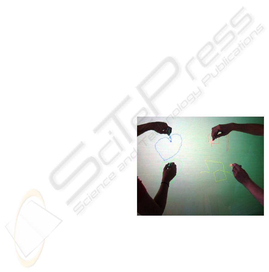
boards, screens or tables. A simple example is the 4-
user drawing-table application in Figure 1. At
Interactivespaces we have developed several design
concepts for homes, schools and workplaces
supporting multi-user and social interaction around
2D surfaces such as tables, walls and whiteboards. A
recurring problem to us in this context has been to
find easily available and inexpensive hardware that
supports multi-user interaction - preferably on back-
projected surfaces as these are much more
convenient when several users are involved, due to
the higher risk of casting shadows. Research
prototypes such as DiamondTouch (Dietz, 2001),
and SenseTable (Patten, 2001) can track many
objects simultaneously but suffer from complexity
and lack of availability as well as the use of front
projection. Commercial products like DViT from
Smart Technologies can track 2 fingers or pens
simultaneously, but are expensive and cannot
discriminate valid objects from other (non-valid)
objects on the surface. Thus, multi-object tracking
systems of today are not yet easily accessible to
application developers.
Figure 1: MultiLightTracker used with a simple
simultaneous 4-user drawing application.
In this paper we present MultiLightTracker
(MLT), a novel system that realizes 2D position
tracking of a number of simple objects on a planar
semi-transparent surface without using custom or
expensive hardware or software – only standard
Light Emitting Diodes (LEDs), a camera and a
recent PC is used. The tracking software is based on
EyesWeb (EyesWeb, 2005), a freely available and
easy-to-use signal processing application, containing
245
Nielsen J. and Grønbæk K. (2006).
MULTILIGHTTRACKER: VISION BASED MULTI OBJECT TRACKING ON SEMI-TRANSPARENT SURFACES.
In Proceedings of the First International Conference on Computer Vision Theory and Applications, pages 245-252
DOI: 10.5220/0001374002450252
Copyright
c
SciTePress
predefined function blocks for different data types
and -operations.
To sum up, the key features of this setup are the
following :
• the tracking system is based on use of a semi-
transparent surface and supports simultaneous
back-projection, producing an environment very
suitable for multi-user interaction.
• the hardware setup is physically robust as it is
placed behind the interaction surface - out of
reach from the users.
• the used hardware is off-the-shelf and
affordable; we use Universal Serial Bus (USB)
webcams or DV cams (IEEE1394), Light
Emitting Diodes (LEDs) and a recent PC.
• the vision tracking- and network software used
is freely available for non-commercial purposes.
The paper is structured as follows: First we
describe the hardware setup, next we describe the
MLT software. This is followed by a performance
study, then we discuss challenges, application
scenarios and related work. Finally we discuss future
work and conclude the paper.
2 HARDWARE SETUP
We focus on the implementation of a computer
vision system that processes the video stream of a
single video camera. We equip each of the objects to
be tracked with one or more uniquely colored high-
intensity LEDs, enabling us to detect and track the
colored light spots with the camera.
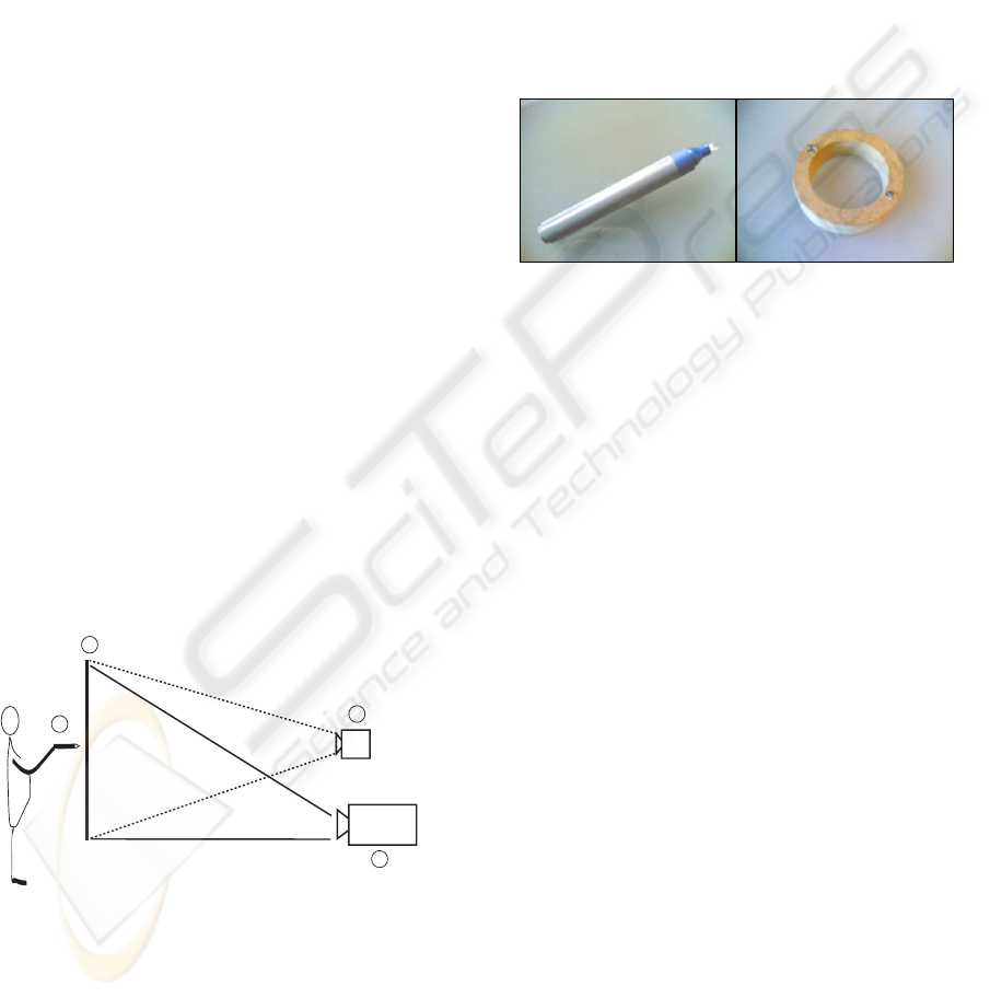
3
2
1
4
Figure 2: Example of a vertical MLT setup.
An example MLT setup is shown in Figure 2 where
(2) is a semi-transparent surface – a sheet of glass
with either a sand blasted back side or a matte film
can work, but a professional low-gain back-
projection screen is optimal for exploiting the full
potential of the system and will also greatly improve
image quality when using back-projection (4). It is
important that the camera (3) and projector are both
placed behind the tracking surface to avoid shadows
from users and camera overload due to direct
projector light exposure. The camera is connected to
a PC (not shown). The system tracks the light from
one or more uniquely colored LEDs embedded in
each object (1). The object can be in form of a pen, a
puck or another shape - see Figure 3 for examples.
The setup may be angled arbitrarily from vertical to
horizontal and common interaction techniques such
as single / double click and gesture tracking may be
supported for multiple objects simultaneously.
Figure 3: Interaction objects. Left: pen for normal 2D
interaction. Right: “donut” with 2 different-colored LEDs
allowing additional rotation sensing.
2.1 Multiple Object tracking
dependencies
Successful tracking of multiple objects in MLT
depends strongly on the systems ability to always
clearly and exclusively see, and uniquely
distinguish, the different LED colors. The maximum
number of tracked objects is thus constrained by
these factors :
• The ability to effectively control the camera
gain and shutter, keeping unintended light – i.e.
ambient light and back-reflection of the projected
image - below the camera threshold.
• The available LED colors and their spectral
distance (see Table 1) as well as sufficient (and
stable) LED light output to overcome the camera
threshold without overloading the camera.
• The system’s color stability over the whole
surface. A combination of the camera’s color
resolution and the color distortion of lenses and
eventual mirrors.
Currently the system supports 4 simultaneous
colors but ongoing work is aiming to extend this
number. With 4 colors the system easily supports
two-handed and/or multi-user interaction as well as
VISAPP 2006 - MOTION, TRACKING AND STEREO VISION
246
objects with more than one LED embedded. This
can enable the orientation of the object to be
detected (see Figure 3).
2.2 Back projection
MLT can be used without projection but a rear
mounted projector (Figure 1 item 4) can be used to
provide graphical feedback directly on the surface.
MLT is able to track the LED-equipped objects
regardless of the presence of a back-projected
image, provided the back-reflection from the
diffusion layer is not too strong. This can be
minimized by reducing projector intensity and by
using a diffusion layer with a low gain factor.
Apart from being required for back-projection,
the diffusion layer helps ensure the camera will
always see the LED light more evenly. Many LEDs
have a very narrow angle of output (< 20 deg.)
which can pose problems when the LED is not
facing the camera lens directly. This can happen
when the user tilts the LED or when the LED is used
near the edge of the surface.
2.3 Use of mirrors
In many back projection setups it is necessary to
apply mirrors in order to achieve projections of the
desired size with minimum space requirements.
MLT works well with mirrors but experiments show
that ghost images, produced by the glass layer in
front of the mirroring surface of ordinary mirrors,
can degrade the system’s color separation and
thereby disturb tracking stability and accuracy.
Optimal performance from the projector and the
vision based tracking requires use of front-coated
mirrors, as these do not distort the picture in a
similar way.
2.4 Camera calibration
With normal ambient light and an eventual back-
projection turned on with a high brightness (white)
picture, place the camera so it covers the back of the
chosen interaction surface. Set the camera to manual
shutter speed and gain control. Adjust the gain to
zero and increase shutter speed until nothing is seen
in the picture (approx. 1/1000 sec).
Note that the system will not tolerate strong light
sources such as unscreened lamps or direct sunlight
to hit the interaction surface.
2.5 LED color selection
When selecting LEDs for MLT, choose high-
efficiency colored LEDs with outputs > 3000 mCd
and wavelengths as far apart as you can get. For a
selection of LED colors and their typical spectral
wavelengths, see Table 1.
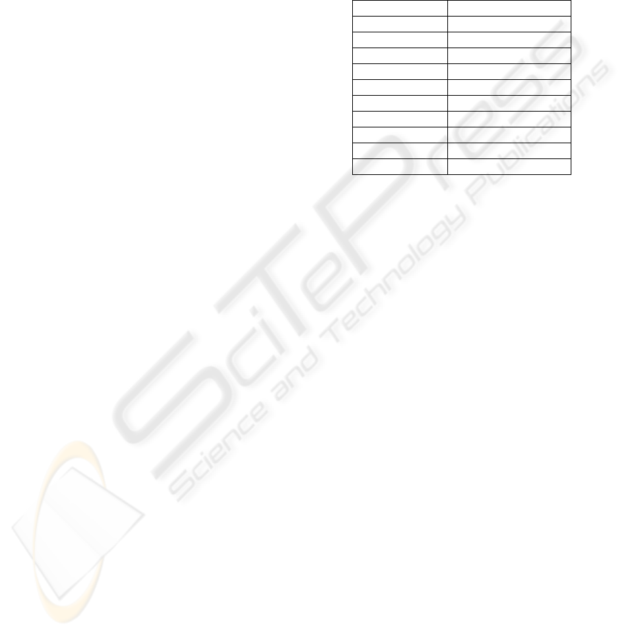
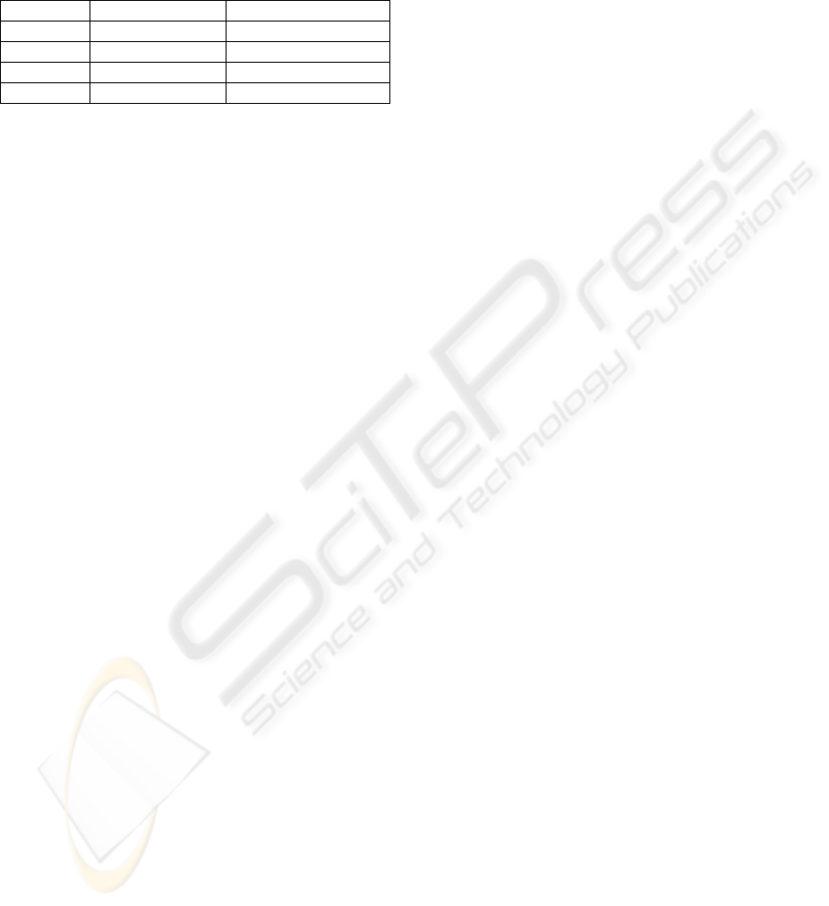
Table 1: Different LED colors and their wavelengths.
Color Wavelength [nm]
Pink 440
Blue 470
Turquoise 490
Cyan 505
True green 525
Green 570
Yellow 590
Orange 605
Red I 630
Red II 660
2.6 LED intensity
As LED intensity varies a lot with model and color,
it is necessary to adjust the different LED intensities
to suit the camera, which will have limited dynamic
headroom now that its auto-shutter and auto-gain
functions are disabled.
LED intensity is tested by first pointing the
chosen LEDs into the interaction surface while
driven at their specified maximum current (typ. 20
mA - consult the data sheet). Locate the weakest
LED still clearly visible in the camera picture. Any
LEDs weaker than this one must either be discarded
or replaced with brighter LEDs. Reduce the intensity
of brighter LEDs (by reducing the current) until all
LEDs show up evenly bright in the camera picture.
Decreasing battery voltage means decreasing
LED intensity. If you are using batteries, you can
either change these often or use a constant-voltage
circuit to drive the LEDs. The description of such a
circuit is, however, beyond the scope of this article.
3 MLT SOFTWARE
ARCHITECTURE
The MLT utilizes computer vision- and color
detection techniques based on the EyesWeb
framework. In Figure 4 a video camera captures
images to a PC. On the PC the camera signal first
enters the camera driver. This is where a manual
sensitivity level is set to match the light conditions
MULTILIGHTTRACKER: VISION BASED MULTI OBJECT TRACKING ON SEMI-TRANSPARENT SURFACES
247
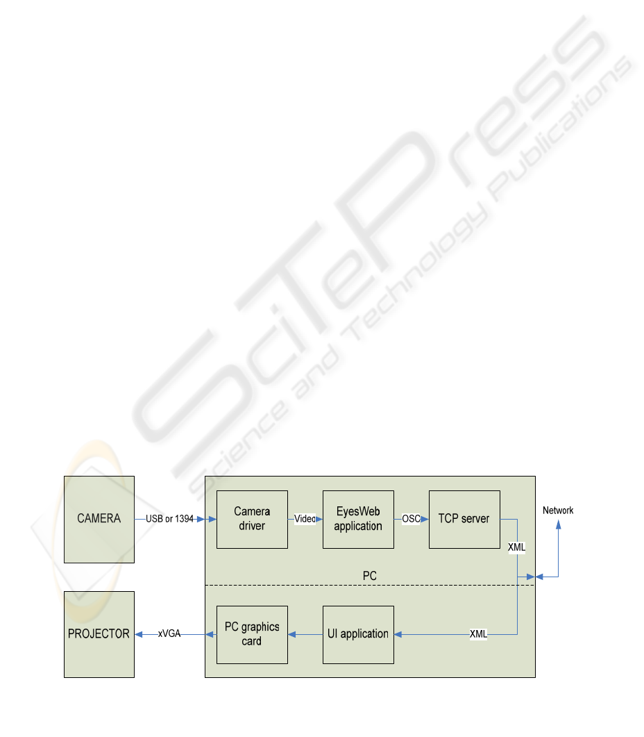
during setup (note that most DVcams have these
controls built into the camera instead).
The video signal then enters the EyesWeb
application which tracks the 2D positions of preset
color blobs in real time. The positions of the tracked
blobs are transmitted from EyesWeb as Open Sound
Control (OSC) (OSC, 2005) messages on a network
socket.
Finally, we are using a TCP server program to
transform the OSC messages into eXtensible
Markup Language (XML) messages. The XML
messages are available on a network socket and can
easily be used by application programmers, i.e. for a
Graphical User Interface (GUI) back-projected onto
the 2D surface.
As shown, a GUI application can run on a
separate machine (illustrated by the dashed line) or
locally on the same machine as MLT if there is
enough processing power available for this.
3.1 The EyesWeb image processing
algorithm
The color tracking is based on EyesWeb which
provides a graphical programming environment
containing predefined function blocks for different
data types and -operations. See Figure 5 for
algorithm architecture.
We have used a multi color tracking block for
video (ExtractMultColors) followed by some data
formatting functions and an OSC network socket
block to output the result of the tracking process.
Going from left to right, the first block is a video
display used to verify the camera input signal. The X
indicates the block is inactive and the blue signal
lines indicates that the signal type is image data.
The next block is the camera input, which can be
either a webcam (shown) or a DVcam input. The
camera feeds two blocks on the right – a (disabled)
display used when calibrating the color tracker
and the color tracker (ExtractMultColors) itself.
The color tracker block can, as its real name
implies, extract multiple colors but we only use it to
track one color as this makes the setup easier to
handle and has shown to give no performance
penalties. To track additional colors we duplicate the
whole setup from the color tracker block onwards,
feeding the camera signal to the added signal chain.
3.2 Calibrating the color tracker
Before calibration is possible, it is necessary to open
the color tracker by double-clicking it and manually
add an entry to the tracking list inside. The entry
includes a name for the blob (which can be the color
name) as well as the area size to search. As you can
never know where a LED will light up and as the
color tracker searches an area centered around the
last occurrence of a color, it is necessary to enter
search dimensions twice the size of the camera’s
resolution to always scan the whole surface.
Above the color tracking block there is a small
block with a tick-box. Once the EyesWeb algorithm
is running, this tick box can be activated along with
the display to the left of the color tracker. It is now
possible to calibrate the color tracker by activating a
LED on the interaction surface and simply double-
click the corresponding color dot in the display.
When calibration is done, close the display and un-
tick the box. This procedure must be repeated for
any additional colors.
3.3 Output processing
The color tracker has several outputs on its right
side, of which 2 is used. At the top is an image
output showing what the color tracker recognizes.
The other output is coordinate data (pink signal).
Figure 4: MLT software architecture. The system can run on a single PC if resources allow it, or be distributed on two
machines (dashed line).
VISAPP 2006 - MOTION, TRACKING AND STEREO VISION
248

The data is shown on-screen by the block with the
“spreadsheet” pattern and contains the name you
entered inside the color tracker along with
coordinates of the color blob. Note that both
coordinate outputs will yield a large negative
number if no color is recognized.
The matrix data is also fed to two rows of blocks
that extract the X- and Y-coordinates, convert the
data from scalar to string and merge the strings with
preset text labels (the VALUE field in Listing 1)
before transmitting the strings in OSC messages. It
is necessary to set a network port in the OSC blocks.
3.4 Communicating data to
applications
The output from EyesWeb is OSC messages but we
have chosen to convert this to XML with the Flosc
server application (Flosc, 2005). This freely
available application is written in Java and includes
full source code, making it easy to make
modifications. For MLT we modified Flosc to only
output XML messages when the received
coordinates are valid (suppressing the large negative
numbers output by EyesWeb when no color is seen).
We also made some modifications to the output
XML format to reduce bandwidth. Here is an
example of the XML output for a blue color X-
coordinate – note that X and Y coordinates are
currently output as separate XML messages :
<XML>
<OSCPACKET>
<PARAMETER TYPE=”s” VALUE=”BLU_X240” />
</OSCPACKET>
</XML>
3.5 Calibrating output coordinates
to the display
No attention has been paid to ensure that the
coordinates coming out of the color tracker matches
the coordinates of the displayed image. This means
that a calibration must be performed before the
system is used. A typical calibration procedure will
project markers in different locations of the screen
and the user must activate a LED over each of these
markers in turn. The system will then detect the
resulting camera coordinates and introduce the
necessary correction. This method can also detect
and correct geometric distortion as a result of the
camera not being placed correctly (skew /
keystoning). Additionally, camera coordinates can
be flipped / mirrored if this was not possible on the
camera or in the camera driver.
As MLT is currently a sensor system outputting
raw data, calibration and data-interpreting tasks are
left to the application receiving the XML data.
3.6 Click functionality
If the LED-equipped objects have a suitable switch
function, either the Flosc application or the
application receiving the XML data can emulate
mouse single- and double-clicking functionality by
measuring the amount of time the LED is turned on
and off.
4 SYSTEM PERFORMANCE
System performance depends on camera resolution,
camera frame rate and the number of colors tracked
by the MLT application. The current version of the
system is running on a Dell Dimension 8400 P4 3,4
GHz with 1GB RAM using a Logitech Quickcam
Pro 4000. All measurements have been performed
on this system configuration.
4.1 System load and response time
Table 2 shows the average tracking latencies and
corresponding system loads for a 640x480 setup
tracking 1 to 4 colors. The latency and load figures
Figure 5: EyesWeb algorithm architecture for tracking a single color.
MULTILIGHTTRACKER: VISION BASED MULTI OBJECT TRACKING ON SEMI-TRANSPARENT SURFACES
249
tend to fluctuate a bit during measurements, so 10
measurements were made and averaging has been
applied.
Table 2 : System performance.
Colors Latency (avg) System load (avg)
1 70 ms 22 %
2 80 ms 33 %
3 90 ms 42 %
4 100 ms 55 %
4.2 Tracking resolution
With a webcam the normal resolutions are 320x240
or 640x480 in 4:3 aspect ratio. With an IEEE1394
DVcam the resolution is 720x540 for PAL 4:3 or
720x405 for PAL 16:9 (most DVcams make 16:9 by
cropping the image).
Tracking 4 colors from a webcam (640x480 @
15fps) and running the additional network socket
loads the hardware between 50 and 60%. In
comparison the same number of colors can be
tracked in 320x240 resolution at only 15% load.
Clearly, reducing the camera resolution also
reduces the load on the processor as the number of
pixels to search fall dramatically. Reducing the
number of colors to look for also reduces processor
load, but not nearly as dramatically. This is probably
because EyesWeb optimizes the algorithm before
executing it and looking for an extra color isn’t a
very demanding task when looking for one in the
first place.
Opting for lower resolution images means you
get lower tracking resolution. Today, projector
resolution is often 1024x768 and webcams will
normally deliver 640x480, resulting in (maximum)
1.6 display pixels per tracked camera pixel. This
does not pose problems with normal window
interaction but is noticeable to some degree in a
drawing situation. DVcams will deliver a bit more
resolution, reducing the max. displayed/tracked pixel
factor to 1.42.
4.3 Frame rate
Reducing the frame rate reduces the load
accordingly. As the camera frame rate is already
low, this will easily become uncomfortable. Tests
show that below 10fps the staggering effect becomes
noticeable when drawing or moving objects.
5 DESIGN ISSUES AND
CHALLENGES
Most camera based systems are sensitive to changes
in light conditions and MLT is no exception. Its
stability depends highly on the effective suppression
of unintended light and the stability of the LED light
sources’ color and intensity. As long as these factors
are well-adjusted and stable, the system will work.
The optical system’s resolution of the color
spectrum puts a limit to the number of simultaneous
objects. Currently we can easily track 4 colors and 6
seems to be realistic but if more objects is desired,
other techniques must be used to distinguish them.
Due to camera- and projector-screen distance
increasing with surface size, MLT setups can
become quite space demanding. This is a limiting
factor for the system’s applicability.
Improvements can be made to the EyesWeb
patch by rewriting it to take over some of the
functionality currently performed by the Flosc
application. This will improve performance as a lot
of unnecessary information is currently being
generated, just to be filtered away in the Flosc
server.
6 APPLICATIONS
The MLT technology has recently been proofed and
tried out for a three week period in a public
installation at a library. Results are very promising,
indicating that the system is sufficiently stable and
robust for use in a public space, although some
testing still remains to reveal its limits. Moreover, it
is planned to use the technology in a number of
future multi-object/multi-user application scenarios,
examples are described below.
Before showing the system in public, it was
decided by the University of Aarhus to apply for a
patent on the technology.
6.1 StorySurfer
In our first example, MLT is used as part of a large
scale interactive space installation - a multi-user
search tool for a children’s interactive library project
at the Main Municipal Library in Aarhus, Denmark.
The setup includes a large camera-tracked, top-
projected floor where the children can select book
categories by keywords and pick out single items by
for further investigation. The selected book cover
objects are transferred to a horizontal MLT table
where up to 4 users can simultaneously browse and
discuss the details of the selected books and print out
VISAPP 2006 - MOTION, TRACKING AND STEREO VISION
250
a slip with directions on how to find the actual
books.
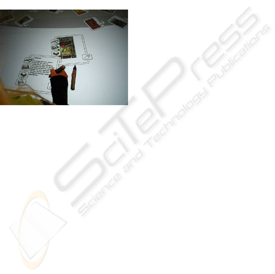
Figure 6 shows the user interface. The book
representation is maximized and moved around the
screen by dragging the hand symbol. Clicking the 4
symbols on the left give access to book facts, book
abstract, a “other users also looked at ...”-function
and a print function.
The children’s interactive library project has not
yet finished and additional research results will
emerge from it during 2006.
Figure 6: The user interface of the StorySurfer table. Note
the high image quality and even light of the low-gain back
projection screen.
6.2 DoHM
Another application example is the interactive home
environment where we have developed a so-called
Domestic HyperMedia system (DoHM) (Petersen,
2004), enabling family members to collaboratively
organize home media material such as pictures,
videos, play lists etc. on the living room table or an
electronic pin board in the entrance hall. With the
MLT it is now easy to transform DoHM clients into
true collaborative applications giving all family
members equal control over the digital material
placed on the living room table, thus supporting the
kind of accessibility and social interaction that was
required from our empirical studies in the domain.
Having finalized the first stand alone testing of
the MLT we are now integrating it in the
applications mentioned here and perform user
evaluation. The MLT is as a first step integrated into
the DoHM MediaOrganizer client.
7 RELATED WORK
The MLT work is aimed at creating a low-level,
event-based input device for different interactive
systems that support single or multiple users
interacting with a single surface. Examples of such
systems are DiamondTouch (Dietz, 2001),
Lumisight Table (Matsushita, 2004), MagicTable
(Bérard, 2005), MetaDESK (Ullmer, 1997) and
Sensetable (Patten, 2001). Compared to these
systems we have developed a significantly simpler
and cheaper hardware setup.
Some of the hardware components, such as the
projector and PC, are standard equipment that is
needed in any setup of this kind. This means
expenses must cover the LED-equipped objects
(they require a little crafting), a webcam and a low-
gain back projection screen. This should not set you
back more than 500-1000 EUR/US$ for a 4 color
setup with a 100-150 cm. screen (diagonal).Front
coated mirrors are expensive – 1000-1500 EUR/US$
per sq.m. but can often do without them - screens
and mirrors can be purchased from companies like
(DNP, 2005) or (DAF, 2005).
By using back-projection and –detection we get
high image quality without shadows and completely
avoid the problems with occlusion that other systems
like ARToolKit (Kato, 2000) have to deal with.
With respect to software, MLT provides a
generic XML based interface over a TCP/IP port
which makes it very easy for application
programmers to prototype and develop client
programs that take advantage of the LED object
tracking. As an example, Macromedia Flash can
read the XML stream directly and makes it easy to
couple tracking of the physical LED objects to
graphical objects in Flash. The socket-based
architecture also supports multi-client setups where
one MLT system can supply multiple client
applications with XML encoded object position data.
Thus, the MLT is easier to integrate with arbitrary
applications than previous systems.
8 FUTURE WORK
In the following we discuss a number of issues and
challenges to address in the future development of
MLT.
Testing of the applicability of RGB (tricolor)
LEDs with MLT has already started as these LEDs
might enable more colors to be used simultaneously
by providing custom colors not available within the
standard LED product range.
Development of a custom EyesWeb processing
block, integrating data filtering, formatting and
MULTILIGHTTRACKER: VISION BASED MULTI OBJECT TRACKING ON SEMI-TRANSPARENT SURFACES
251

direct XML output to a network socket will simplify
the architecture of the MLT and reduce both
processing load and tracking latency. This process
could further lead to the development of a single
standalone image processing application, containing
all the software processes of the MLT system.
Development of a multi-projector and multi-
camera setup for large surfaces will allow whole
walls or floors to be turned into multiuser interaction
surfaces. This will require further development of
the Flosc server, as this will initially be the point
where data streams from several Eyesweb color
trackers are joined together.
9 CONCLUSION
This paper has introduced the MultiLightTracker
(MLT) system for simultaneous vision based
tracking of multiple objects on semi-transparent 2D
surfaces. We have described the object tracking
approach and how it enables direct multi-user
interaction with back projected content.
MultiLightTracker has initially been calibrated to
track four different-colored objects simultaneously
but it will extend to track additional simultaneous
objects. MultiLightTracker is sufficiently robust for
everyday collaborative use and is superior to
existing multi-object tracking surfaces with regards
to its simplicity and low cost. We have reached a
stage where MultiLightTracker is now being
integrated with applications for home and public
environments, leading to evaluations in real use
situations.
10 ACKNOWLEDGEMENTS
The authors wish to thank all colleagues at
Interactivespaces for their help and support with the
development of MLT and this paper.
Special thanks goes to architects Andreas Lykke-
Olesen and Tina Christensen for contributing with
photos and illustrations to the project.
REFERENCES
Bérard, 2005. Bérard, F., The Magic Table: Computer-
Vision Based Augmentation of a Whiteboard for
Creative Meetings. Presented at the IEEE
International Workshop on Projector-Camera
Systems. June 25, 2005, San Diego, California, USA
DAF, 2005: http://www.dafscreens.com/
Dietz, 2001. Dietz, P.H.; Leigh, D.L., DiamondTouch: A
Multi-User Touch Technology. ACM Symposium on
User Interface Software and Technology (UIST),
ISBN: 1-58113-438-X, pps 219-226, November 2001.
ACM Press.
DNP, 2005. http://www.en.dnp.dk/get/2821.html
EyesWeb, 2005. http://www.eyesweb.org/
Flosc, 2005. http://www.benchun.net/flosc/
Kato, 2004. Kato, H., Billinghurst, M., Poupyrev, I.,
Imamoto, K., Tachibana, K. (2000) Virtual Object
Manipulation on a Table-Top AR Environment. In
Proceedings of the International Symposium on
Augmented Reality, pp.111-119, (ISAR 2000), Munich,
Germany.
Matsushita, 2004. Matsushita, M., Iida, M. and Ohguro, T.
Lumisight Table: A face-to-face Collaboration
Support System That Optimizes Direction of Projected
Information to Each Stakeholder. In CSCW’04,
November 6-10, 2004, Chicago, Illinois
OSC, 2005. http://www.opensoundcontrol.org/
Patten, 2001. Patten, J., Ishii, H., Hines, A.J. & Pangaro,
G.: Sensetable: a wireless object tracking platform for
tangible user interfaces. In Proceedings of the SIGCHI
conference on Human factors in computing systems.
Seattle, Washington, United States, 2001 pp. 253-260.
ACM Press.
Petersen, 2004. Petersen, M. G., and Grønbæk, K. (2005):
Interactive Spaces: Towards Collaborative Structuring
and Ubiquitous Presentation in Domestic
Environments. In Australasian Journal of Information
Systems(AJIS).
Ullmer, 1997. Ullmer, B. and Ishii, H., The metaDESK:
Models and Prototypes for Tangible User Interfaces.
In Proceedings of Symposium on User Interface
Software and Technology UIST'97, (Banff, Alberta,
Canada, October, 1997). ACM Press.
VISAPP 2006 - MOTION, TRACKING AND STEREO VISION
252
