
MOTION TRACKING WITH REFLECTIONS
3D pointing device with self-calibrating mirror system
Shinichi Fukushige, Hiromasa Suzuki
Department of Precision Enginieering, The University of Tokyo,7-3-1 Hongo Bunkyo, Tokyo, Japan
Keywords: Interactive pointing device, 3D input, reflections, motion tracking.
Abstract: We propose a system that uses a camera and a mirror to input behaviour of a pointer in 3D space. Using
direct and reflection images of the pointer obtained from single directional camera input, the system
computes the 3D positions and the normal vector of the mirror simultaneously. Although the system can
only input the ‘‘relative positions’’ of the pointer, in terms of 3D locations without scale factor, calibration
of the mirror orientation is not needed. Thus, the system presents a very simple and inexpensive way of
implementing an interaction device.
1 INTRODUCTION
Input devices for processing 3-dimensional (3D)
computer-generated models are divided into two
types - those with a 2-dimensional (2D) interface
and those with a 3D interface. 2D input devices,
such as mice, tablets, and touch monitors, are used
more widely than 3D input devices because of their
simplicity and easy-use. However, because the target
is in 3D space, 2D-base-input equipment needs
several constrains and restrictions of pointer
movements (Sugishita, 1996) (Zeleznik, 1996)
(Branco, 1994). Preconditions, for translating 2D
input operations into 3D, often hinder the intuitive
input operations of designers.
Therefore, recently, various devices have been
developed which can directly indicate the position
on 3D space.
Currently, however, 3D input devices are not
widely used among general users and are not used as
general-purpose tools due to their costs and
complexity, requiring special sensors for treating
magnetism, ultrasonic waves and laser, or having
complex structures, such as joint or wire
mechanisms or stereo camera systems (Kenneth,
1994) (Sato, 2000) (Smith, 1995) (Turban, 1992).
Stereovision is commonly used to calculate 3D
positioning of a pointer by implementing images
from more than one single camera (Faugeras, 1993)
(Yonemoto, 2002) (Xu, 1996) (Longuet-Higgins,
1981). However, processing multiple video images
in real time thus requires large amount of CPU
resources or special hardware. Furthermore, these
methods involve synchronization and complex
computations that usually require an initial
calibration phase. Since multiple cameras must be
placed at separated positions to ensure full 3D
restoration accuracy, it is difficult to miniaturize
such systems.
We would like to provide a simple 3D pointing
device that users can handle easily and with a feeling
of familiarity. This paper proposes a system for
assuming the 3D motion of a pointer in real time by
inputting a single video image of the pointer tip with
a mirror reflection. Conventionally, in order to
determine an object's 3D positioning from a single
view, the shape and size of the object or multiple
markers on it should be recognized simultaneously.
And the restoration accuracy of them are low in the
direction of the optical axis.
The proposal method is different from the
method of Lane et al (Lane, 2001), which also uses a
mirror reflections and estimates the ‘‘absolute’’ 3D
positions. This method needs manual calibration and
must divide the 3D space into a mirror reflection
area and an inputting area.
We propose using a mirror system with self
calibration which estimates the relative 3D positions
of the pointer. ‘‘Relative positions’’ mean that the
restored x, y, z coordinates of the pointer include the
same unknown parameter regarded as a scale factor.
However, in the 3D pointing usage, the scale
factor can be set freely by a user, because the fine
428
Fukushige S. and Suzuki H. (2006).
MOTION TRACKING WITH REFLECTIONS - 3D pointing device with self-calibrating mirror system.
In Proceedings of the First International Conference on Computer Vision Theory and Applications, pages 428-434
DOI: 10.5220/0001377404280434
Copyright
c
SciTePress

motion tracking is more important than inputting
absolute positioning value in the real world.
2 PRINCIPLE OF 3D MOTION
TRACKING FROM SINGLE
DIRECTIONAL IMAGES
Under the principle of estimating the 3D motion of a
pointer via a single camera images, we use
reflections of a mirror plane. We assume the internal
camera parameters such as focal length are pre-
calibrated. And normalized camera coordinates are
used. The image plane of the normalized camera is
in the place of unit length, i.e., 1 from a focal point,
i.e., the
z
axis is taken as direction of the optical
axis of a camera, and
1=z
is the image plane. Any
standard camera may be used, because any standard
camera image coordinates can be easily converted
for normalized image coordinates. We can thus
consider the problems of vision using a normalized
camera regardless of individual camera parameters
(Xu, 1996).
2.1 Self-calibration of the System
Initially, the proposal system estimate the orientation
of the mirror by using the 2D positions of direct and
reflected pointer images projected on a camera’s
image plane (see Figure 1).
Figure 1: Over view of the proposal system.
The
),,(
zyx
NNN=N
is the foot point of the
camera's focal point
)0,0,0(
=
O
to the mirror
plane. And the normal vector of the mirror
N
λ
can
be estimated from projected images of the 3D point
P
which is the tip of the pointer moving freely in
the 3D space. Thus, we can get more than four
projected 2D points from more than two 3D points
by tracking the movement of
P
.
Supposing that, at one time, the point is located
on
1
P
, and at other time it is located on
2
P
(
21
PP ≠
). Then,
)1,,(
11 yx
mm=
1
m
and
)1,,(
222 yx
mm
=
m
are the points projected directly
onto the image plane, and
)1,,(
11 yx
mm
′′
=
′
1
m
and
)1,,(
222 yx
mm
′
′
=
′
m
are the points reflected by the
mirror and projected onto the image plane from
1
P
and
2
P
respectively (see Figure 2).
Reflection of light from a mirror is governed by
the two Laws of Reflection:
(1) The incident ray, reflected ray and normal at the
point of incidence lie on the same plane.
(2) The angle which the incident ray makes with the
normal (angle of incidence) is equal to the angle
which the reflected ray makes with the normal
(angle of reflection).
From the law (1), relation among
1
m
,
1
m
′
,
2
m ,
2
m
′
and
N
is written as follows:
Nmm
=
′
+
1111
β
α
(1)
Nmm
=
′
+
2222
β
α
(2)
Where, only the
1
m ,
1
m
′
,
2
m and
2
m
′
are given
value and are on the same plane (z=1). Here
the
1
α
,
2
α
,
1
β
and
2
β
are scalar.
Figure 2: The point P moves from the position P1 to P2.
But, at this time, directly projected points and
reflected points have not been distinguished. Using
those four 2D points, there can be six straight lines
that pass by the every two points and intersect at the
three points shown as Figure 3.
Figure 3: The four projected points and the six straight
lines that pass by the every two points.
MOTION TRACKING WITH REFLECTIONS - 3D pointing device with self-calibrating mirror system
429
Two of these six lines are the nodal lines of the
image plane and the two planes described as (1) and
(2). Thus, in an ideal case, these two lines should
always intersect at the same point
)1,,(
ˆ
zyzx
NNNN=N
which is the intersection
point of the image plane and the line extended to
N
from the focal point
O
.
Therefore, one of the three intersection points,
whose movement is minimum can be thought as the
N
ˆ
. And the points near
N
ˆ
on the lines is reflection
point, and the points far from
N
ˆ
can be the directly
projected points.
Also
N
lies on the intersection line of the two
planes (1) and (2). From these formulas, the
N
λ
is
determined as follows:
xyyxxyyx
xyxyyxyxz
xyyyyxyxyxyy
xyyyxyyyxyyxy
xxyyxxxxyxxy
xyxxyxyxxyxxx
mmmmmmmm
mmmmmmmmN
mmmmmmmmmmmm
mmmmmmmmmmmmN
mmmrmmmmmmmm
mmmmmmmmmmmmN
21211211
21212121
212211211221
121221121211
21211211121
211221121221
′′
+
′′
−
′
+
′
−
′
−+−
′
=
′′
+
′′
−
′
−
′
−
′
+
′
+
′
−
′′
=
′′
+
′′
−
′′
−
′
+
′
′
+
′
−
′
−
′
=
λ
λ
λ
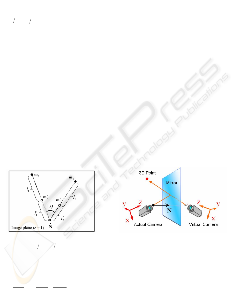
The accuracy of the estimated
N
λ
depends on the
combination of the four projected points. From the
lows of reflection (1), the relation among the four
points on the image plane is shown as Figure 4.
Figure 4: The four projected points on the image plane.
Where,
)1,,(
ˆ
zyzx
NNNN=N
is the intersection
point of the image plane and the line extended to
N
from the focal point
O
. We suppose that the
accuracy of the
N
λ
is evaluated with evaluation
function
E
defined by
⎟
⎟
⎠
⎞
⎜
⎜
⎝
⎛
′
+
′
+
′
+
′
+=
22
2
11
1
sin
1
ll
l
ll
l
E
ϕ
θ
(3)
Where
ϕ
is a constant (7.5 in our experiments), and
||
ˆ
||||
ˆ
||
||)
ˆ
()
ˆ
(||
sin
1
1
2
2
mNmN
mNmN
−−
−×−
=
θ
||||
111
mm
′
−
=
l
,
||
ˆ
||
11
Nm −
′
=
′
l
||||
222
mm
′
−
=
l
,
||
ˆ
||
22
Nm −
′
=
′
l
While calibrating the normal of the mirror, the
user ought to move the pointer widely, and the
system tracks the four projected points and gets
1
m ,
1
m
′
,
2
m and
2
m
′
, which minimize
E
.
2.2 Restoring the 3D Motion of the
Pointer From 2D Images
Using the concept of a virtual camera, the camera is
set virtually to the opposite side of the mirror from
an actual camera. Images reflected by the mirror can
be calculated as being shot directly by the virtual
camera (see Figure 5). Actually, there is no virtual
camera’s image plane. However, it can be regarded
as overlapping onto the image plane of the actual
camera.
We set
r
C as actual camera coordinates and
v
C as virtual camera coordinates.
Figure 5: The virtual camera is set to the opposite side of
the mirror from the actual camera.
r
C is field symmetrical with
v
C . The relation
between two coordinates is thus set as follows:
tRCC
vr
+
=
(4)
R
expresses rotational movement and t expresses
parallel translation movement to
r
C
from
v
C .
Then
VISAPP 2006 - MOTION, TRACKING AND STEREO VISION
430
T
2nnI
R
−=
⎥
⎥
⎥
⎦
⎤
⎢
⎢
⎢
⎣
⎡
−−−
−−−
−−−
=
2
2
2
2122
2212
2221
zzyzx
xyyyx
yxyxx
nnnnn
nnnnn
nnnnn
(5)
Nt 2=
(6)
Where,
),,(
zyx
nnn=n
is the unit normal vector of
the mirror, thus
||/ NNn =
.
The 3D position of the pointer
P
is calculated
with the two points
)1,,(
yx
mm=m
,
)1,,(
yx
mm
′
′
=
′
m
projected onto the image plane. We can consider
m as the point being shot by the actual camera
r
C
,
and can consider
m
′
as the point of the virtual
camera
v
C .
The two lines extended toward
m and m
′
from
each camera’s focal point should intersect at the
same point
P
in an ideal case. From the formula (4),
this relation is described:
tmRm +
′′
= ss (7)
Where,
ms and m
′′
s are the 3D positions of
P
in
the coordinates
r
C and
v
C respectively. When
m
′′
s is translated to the coordinates
r
C , it becomes
right side of the formula (7). Although
N
is not
given, the normal vector of the mirror
N
λ
is
predetermined at the self-calibration phase. Then,
(7) is changed to
NmRm
λ
+
′′
= ss (8)
Unfortunately,
s and s
′
, which satisfy this
formula, may not be found due to errors included in
N
λ
and camera parameters.
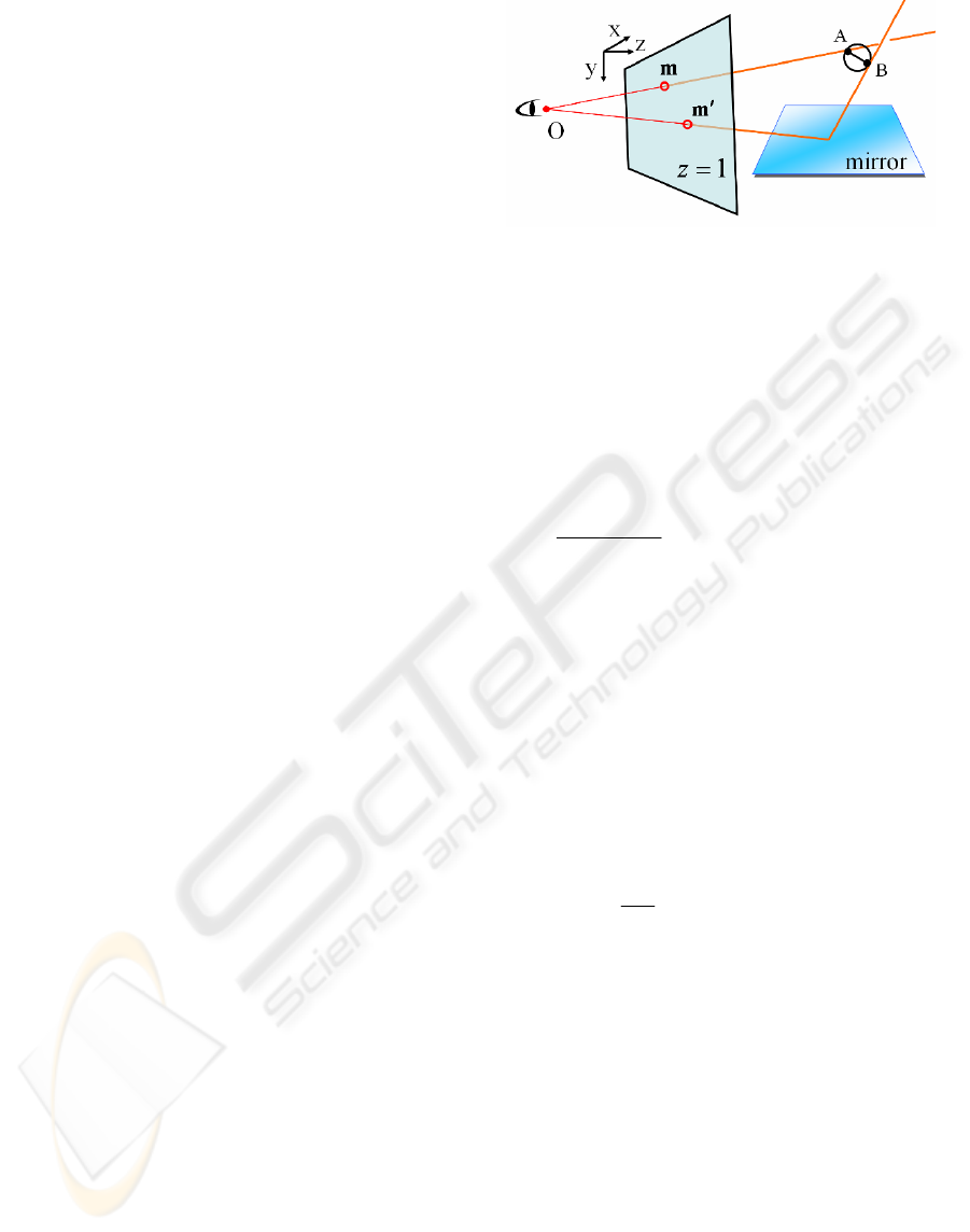
This means that the two lines do not always
intersect. Then we define the ‘‘intersection point’’ as
the centre of the smallest sphere to which both lines
are tangential. Consider the case in which the two
lines are respectively tangential to the sphere at a
node A,
m
t
, and a node B,
NmR
λ
+
′′
t
as illustrated
in Figure 6.
Figure 6: The two lines which tangential to the sphere at a
node A and B.
Here the
t
and
t
′
are scalar.
By defining a unit vector directed from node A
to node B as
d
and the distance between these two
nodes as
u
, the node B can be determined as
NmRdm
λ
+
′
′
=
+
tut (9)
Since the two lines are perpendicular to line AB,
the unit vector
),,(
zyx
ddd
=
d
is denoted as
|||| mRm
mRm
d
′
×
′
×
=
(10)
Therefore, the three remaining unknowns
t
,
t
′
and
u
in (9) can be obtained by solving the matrix
expression of:
1
)21(22
2)21(2
22)21(
2
2
2
−
⎥
⎥
⎥
⎦
⎤
⎢
⎢
⎢
⎣
⎡
′
−−
′
+
′
′
+
′
−−
′
′
+
′
+
′
−−
⎥
⎥
⎥
⎦
⎤
⎢
⎢
⎢
⎣
⎡
=
⎥
⎥
⎥
⎦
⎤
⎢
⎢
⎢
⎣
⎡
′
zzyzyxzxzz
xyyyxyxyy
zyxyyxxxxx
z
y
x
mnmnnmnndm
mnnmnmnndm
mnnmnnmndm
N
N
N
t
u
t
λ
(11)
Finally, the point of intersection, which therefore
is assumed to be the location which is the middle
point of A and B, can be determined as
2
d
mP
u
t +=
(12)
The three scalar
t
,
t
′
and
u
are all include a
remaining unknown
λ
shown as (11). This can be
regarded as a scale factor. We can give free values to
λ
in the virtual space.
3 EXPERIMENTAL RESULTS
We present the inputting experiments with our
proposed system. The internal camera parameters
are as follows:
[resolution of camera image] 640
×480 pixels
[camera focal distance] 3.73
[angle of view] vertical: 31.2°, transverse: 39.6°
MOTION TRACKING WITH REFLECTIONS - 3D pointing device with self-calibrating mirror system
431

Figure 7: The mirror system with a LED pointer.
We use two types of pointers, i.e., a stylus with a
LED at the nib, and the fingertips.
The pointer with the LED uses the properties of
a light emitting tool, which include information such
as color, lighting, darkness, blinking, etc., of the
LED with button operation. Those signals provide
variety of operations such as “a click” and “a double
click”. A clicking is a single blinking and a double
clicking is a continual double blinking within a
second.
The gestures of picking and releasing using two
fingertips can be recognized by the system, and
enable users treat computer-generated objects to be
as in the 3D space.
And the system can be used with a big mirror
fixed on a wall or a ground and with a camera held
by hands, because calibration of the mirror
orientation in the camera coordinates is very easy
and fast (see Figure 8).
Figure 8: A system with a big mirror fixed on a wall and a
hand held camera. (One of the inputting images).
Then, we conduct the input experiment of 3D
curves, surfaces, etc (see Figure 9). The proposed
method can input fine operation at the tip of a
pointer with sufficient balance in all the directions.
Figure 9: Generating a 3D curve and a 3D surface.
The cost of calculation is comparatively low
because only one image obtained from single camera
is processed. This enables real time tracking of
projected points, restoration of 3D motion and
orientation of the mirror by only CPU processing.
3.1 Space Resolution
For 3D pointing devices, the resolution of space in
which we input motions reflects more about system
performance. The sensitivity to relative movement
of pointer operation thus strongly influences the
“feel” of use more than absolute positioning
accuracy.
We then consider “space resolution” as a
criterion showing the ability of how dense the
system samples a space.
Space resolution is defined as the minimum
distance among the 3D operations of a pointer that
the system can recognize.
The resolution in a 2D digital image is, if
expanded onto 3D, expressed as a spatial spread of a
4-sided pyramids as shown in (see Figure 10). The
3D resolution is calculated by an intersection area of
two 4-sided pyramids that are extended from directly
projected image pixels and reflected image pixels.
As long as the centre of the pointer tip moves inside
the 4-sided pyramids, movement does not appear in
the image and it is not recognized by the system.
CCD Camera
Monitor
Mirror
LED Pointer
3D Object
VISAPP 2006 - MOTION, TRACKING AND STEREO VISION
432
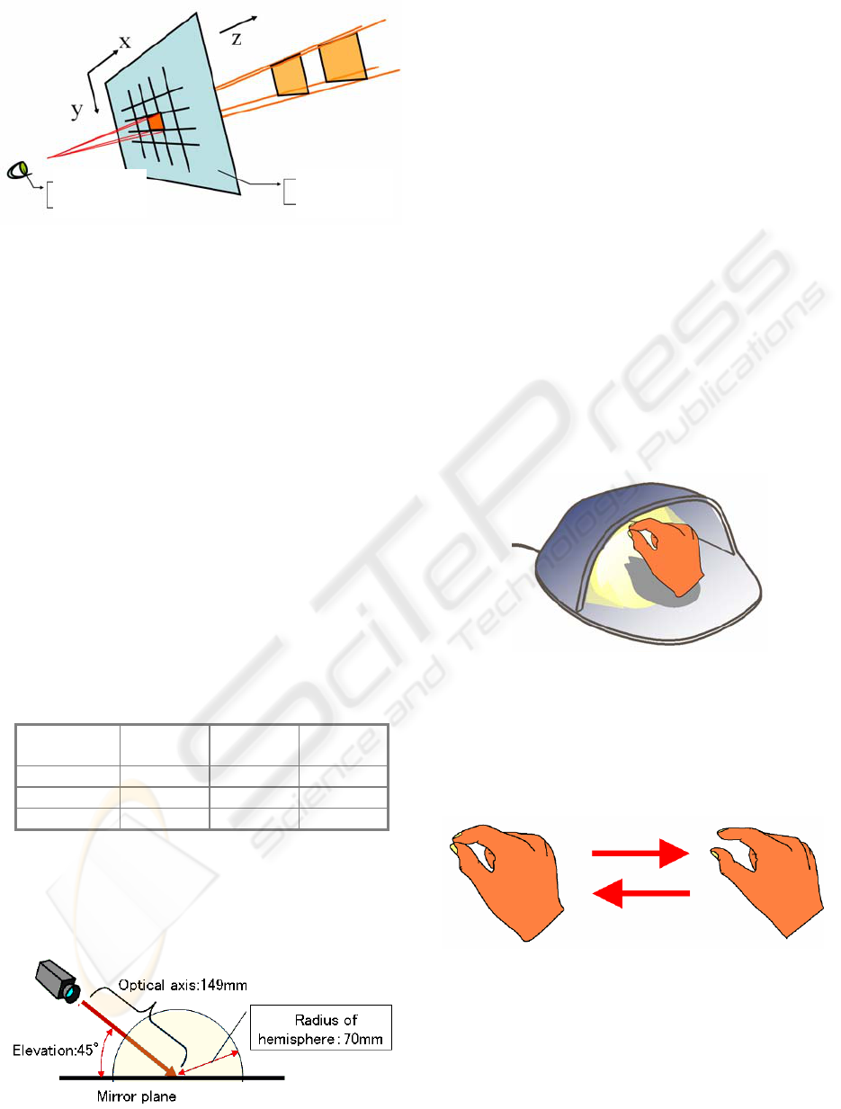
Figure 10: A digital image and an extended pyramid area.
For comparison, we introduce two conventional
techniques estimating the 3D position of a pointer
via single directional camera input.
1) SPHERICAL MARKER
A spherical marker is at the tip of the pointer, and
used for estimating the 3D position from the 2D size
of the sphere projected on the image plane.
2) PLURAL MARKERS
Three markers are attached at equal intervals to a
pen-like pointer to restore the 3D position of the
markers from the 2D position where the three
markers are projected to the image plane. The
distances between each marker are given.
The resolution of the direction perpendicular to
the optical axis (
xy
direction of an image plane)
becomes the same as each of the techniques of
spherical and multiple markers. However, the
resolution to the optical axis direction is not the
same as shown in (see Table 1).
Table 1: Averages of space resolutions.
X
(width)
Y
(height)
Z
(depth)
Mirror System 0.13mm 0.13mm 0.31mm
Sphere Marker 0.14mm 0.19mm 0.62mm
Plural Markers 0.13mm 0.20mm 0.48mm
Here, we calculate the average of space
resolutions in the area of hemisphere shown as (see
Figure 11), and setting conditions of the system are
as follows:
Figure 11: The area of sampling hemisphere.
4 CONCLUSIONS
We have proposed a real-time method for restoring
the 3D motion of a pointer by using single
directional video input. Conventionally, to obtain an
object's 3D position from a single view, the shape
and size of an object or plural markers on it had to
be recognized simultaneously. Such a method,
however, makes restoration accuracy low.
We use mirror images of the pointer to enable us
to input fine 3D motion of objects such as a light
emitting pointer and fingers. We constructed a
simple, compact system as a desktop tool, and the
relative locations of the camera and the mirror are
self-calibrated. By processing the pointer images, we
implemented mouse button functions such as
clicking.
The method we have proposed can be
constructed using simple, common components such
as a camera, a mirror. This makes them applicable in
a variety of situations. As shown in (Figure.12), we
consider a single desktop tool with a built-in camera.
Figure 12: A simplified desktop tool.
The principle of the system can be used for
without the stylus tools, recognizing gesture input
with 3-dimensional manual operation shown as
Figure 13.
Figure 13: A gesture of picking and releasing.
Our proposal was implemented using gestures
such as picking or releasing objects with the
fingertip, but more complicated operation is possible
using all of the fingers, e.g., for turning or changing
a computer-processed object manually.
Image Plane
Focal Point
Pyramid Area
Image Pixel
MOTION TRACKING WITH REFLECTIONS - 3D pointing device with self-calibrating mirror system
433

REFERENCES
Kenneth, J., Massie, T., 1994. The PHANToM haptic
interface: A device for probing virtual objects. In
ASME International Mechanical Engineering
Expotion
and Congress Chicago.
Sato, M., Koike, Y., 2000. Process division in haptic
display system. In Proceedings Seventh International
Conference on Parallel and Distributed Systems., pp.
219–224.
Smith, J. R., 1995. Field mice: extracting hand geometry
from electric field measurements. In IBM Systems
Journal, Vol. 35, No. 3&4.
Yonemoto, S., Taniguchi, R., 2002. High-level Human
Figure Action Control for Vision-based Real-time
Interaction, In Proc. Asian Conf. on Computer Vision.
Sugishita, S., Kondo, K., Sato, H., Shimada, S., 1996.
Sketch Interpreter for geometric modelling, In Annals
of Numerical Mathematics 3, pp. 361–372.
Zeleznik, R. C., Herndon, K. P., Hughes, J. F.,1996.
SKETCH: An Interface for Sketching3D Scene, In
Proceedings of ACM SIGGRAPH ’96, pp. 163–170,
ACM Press.
Branco, V., Costa, A., Ferriera, F. N., 1994. Sketching 3D
models with 2D interaction devices, In Proc. of
Eurographics’94, volume 13, pp. 489–502.
Turban, E., 1992. Expert Systems and Applied Artificial
Intelligence, pp. 337-365, Prentice Hall.
Faugeras, O. D., 1993. Three-dimensional computer
vision: A Geometric Viewpoint. MIT Press,
Cambridge, MA.
Xu, G., Zhang, Z., 1996. Epipoolar Geometry in Stereo,
Motion and Object Recognition. Kluwer Academic
Publishers.
Longuet-Higgins, H. C., 1981. A computer algorithm for
reconstructing a scene from two projections. Nature,
293:133-135.
Lane, J., Lalioti, V., 2001. Interactions with reflections in
virtual environments. In Proc. AFRIGRAPH '01: The
1st international conference on Computer graphics,
virtual reality and visualisation, p87-93.
VISAPP 2006 - MOTION, TRACKING AND STEREO VISION
434
