
A DIFFERENTIAL GEOMETRIC APPROACH FOR VISUAL
NAVIGATION IN INDOOR SCENES
L. Fuentes and M. Gonzalo-Tasis
MOBIVA Group
University of Valladolid
G. Bermudez and J. Finat
MOBIVA Group
University of Valladolid
Keywords:
Visually Navigation, Motion Analysis, Matching Correspondence and Flow, Kalman Filtering.
Abstract:
Visual perception of the environment provides a detailed scene representation which contributes to improve
motion planning and obstacle avoidance navigation for wheelchairs in non-structured indoor scenes. In this
work we develop a mobile representation of the scene based on perspective maps for the automatic naviga-
tion in absence of previous information about the scene. Images are captured with a passive low-cost video
camera. The main feature for visual navigation in this work is a map of quadrilaterals with apparent motion.
From this mobile map, perspective maps are updated following hierarchical grouping in quadrilaterals maps
given by pencils of perspective lines through vanishing points. Egomotion is interpreted in terms of maps of
mobile quadrilaterals. The main contributions of this paper are the introduction of Lie expansion/contraction
operators for quadrilateral/cuboid and the adaptation of Kalman filtering for moving quadrilaterals to estimate
and predict the egomotion of a mobile platform. Our approach is enough modular and flexible for adapting to
indoor and outdoor scenes provided at least four homologue cuboids be present in the scene between each pair
of sampled views of a video sequence.
1 INTRODUCTION
Visually based automatic navigation for platforms is a
common subject in Motion Planning and Navigation
along the nineties, with a lot of applications, includ-
ing interactive wheelchairs navigation. This prob-
lem has been also developed in several related works
(P. Trahanias and Orphanoudakis, 1997), including
landmarks (M. Rous and Kraiss, 2001), stereo vision
(Mazo and et al, 2002) for navigation robotics. Local-
ization of beacons, simultaneous correspondence be-
tween homologue points increase the computational
cost and troubles for decision making.
The design of smart wheelchairs with sensor fusion
and hybrid control is an active research subject(Mazo
and et al, 2002) (Levine et al., 1999) (R. Simpson
and Nourbakhsh, 2004) (Yanco, 1998). Two main
problems concern to safety tasks based in reactive be-
havior (Cort
´
es et al., 2003) and navigation-oriented
tasks focused towards the generation of environment
maps and motion planning (Yuki, 2000). Changing
or non-structured environments, and complex inter-
actions with the environment are benefited from vi-
sual information. Active and passive sensors can be
used for semi-automatic or automatic navigation with
wheelchairs (A. Pruski and Morre, 2002). Active sen-
sors are crucial for obstacle avoidance, but a reactive
behavior is not enough for complex tasks in unknown
environments. An accurate and robust motion plan-
ning, requires detailed information about the scene for
mapping and localizations tasks (P. Trahanias and Or-
phanoudakis, 1997). Modeling intelligent behaviors
for wheelchairs have received an important attention
along last years and it is the main motivation for this
work. Nevertheless, the present approach is focused
towards the exploitation of information provided by
a low-cost video camera. Range sensors require in-
formation fusion and often provide incomplete infor-
mation about changing environment, with some lim-
itations linked to reactive behavior. A low-cost non-
calibrated camera mounted in a mobile platform pro-
vides global information about the scene, which can
be corrected, updated and completed with range sen-
sors for metric information (A. Pruski and Morre,
2002)
Furthermore, to increase the usability in non-
structured environments, it is convenient to avoid bea-
cons or previous information about the scene. To de-
crease the computational effort and to achieve a bet-
ter adaptation to these applications for disabled per-
468
Fuentes L., Gonzalo-Tasis M., Bermudez G. and Finat J. (2006).
A DIFFERENTIAL GEOMETRIC APPROACH FOR VISUAL NAVIGATION IN INDOOR SCENES.
In Proceedings of the First International Conference on Computer Vision Theory and Applications, pages 468-476
DOI: 10.5220/0001378104680476
Copyright
c
SciTePress

sons, we shall suppose that environments are given
by indoor or outdoor architectural scenes. In ordi-
nary architectural scenes it is easy to identify ob-
jects whose boundaries support elements for gener-
ating ”perspective maps” given by vanishing points,
perspective lines and perspective planes. A method-
ology for generating perspective maps is developed in
the §3. Perspective maps provide a 2
1
2
reconstruction.
Most of cameras can be considered as perspective de-
vices which project some part of the visible scene on
the camera plane.
Visual navigation is planned depending on the se-
lection of visual targets. Visual targets must be real-
time located and updated in a faithful representation
of the scene. To simplify, in this work we suppose
that the identification of visual targets or tasks to be
achieved is externally performed by the user; other-
wise, a recognition and a motion planning module
must be added for decision making. A difficult prob-
lem concerns to the representation updating for the
workspace. In this work, the chosen representation
is given by the lifting of quadrilaterals maps Q.A
quadrilateral map is a 2d quadrangular mesh adapted
to a perspective representation of the scene (M. Gon-
zalo and Aguilar, 2002) generated by the intersec-
tion of pencils of perspective lines through vanishing
points.
Edges of Q lie on visible support whose boundaries
provide a support for perspective lines. The computer
management of the image information contained in
each view is performed in terms visible elements. The
information management is performed on a symbolic
representation given by a small subgraph of a quad-
tree corresponding to visible elements in each view.
A characterization of simple events linked to quadri-
laterals of Q simplifies the search of homologue ele-
ments. From the motion viewpoint, evolving homo-
logue quadrilaterals give information about the mag-
nitude and direction of motion changes, involving the
mobile platform itself, and other external agents.
Usual accurate volumetric representations have a
high computational cost, and it is difficult to obtain
a faithful representation of the scene which are up-
dated on-line (twice per second). Corridor scenes are
used in the experimental set-up. In this case, by tak-
ing a mobile reference centered in the mobile object,
at most two vanishing points (v
z
, v
x
, e.g.) are at fi-
nite distance, and at least a third one v
y
is at infinite
distance (vertical lines must be parallel). The simple
nature of analyzed scenes allows to generate maps of
cuboids by intersecting pencils of planes through the
three vanishing lines connecting each pair of vanish-
ing points.
The information management in terms of octrees
has in general a complexity O(N
2
log N) in the num-
ber N of planes of the scene. However, the simple na-
ture of the corridor scene, allows to generate a mobile
perspective representation of the volumetric scene.
Each 3d perspective representation of the whole scene
is obtained by lifting the quadrilateral map Q to a 3D
model. The ordered lifting of the quadrilateral map
has a complexity at most O(N log N) linked to or-
dering planes contained in perspective maps which
are meaningful for visibility issues. The incorporation
of a graphics card would allow to avoid this increasing
thanks to the use of a typical z-buffer algorithm. How-
ever, for lowering costs, a simplified perspective rep-
resentation is introduced, which reduces the computa-
tion to visible cuboids. The resulting maps of cuboids
C play a very similar role to the maps of quadrilater-
als. To give a representation of contraction/expansion
of cuboid/quadrilateral maps we introduce Lie con-
traction/expansion operators along motion directions.
The construction of contraction/expansion operators
between maps of cuboids C and maps of quadrilater-
als Q requires a robust estimation of vanishing points
and the ego-motion description in terms of maps of
quadrilaterals, which is the main contribution of this
work. To achieve it, we use a variant of Kalman Fil-
tering (Marion, 2002)
Kalman filtering is a tool for control of mobile sys-
tems, including motion estimation, tracking, and pre-
diction from estimation. They have been used in Mo-
tion Analysis by Computer Vision, in particular to
provide an assistance for visually guided automatic
navigation. A Kalman filter (Faugeras, 1993) is a
recurrent technique for solving a dynamic problem
by the least squares method. Measures can be cor-
rupted by white noise, and must be corrected. In this
work, an adaptation of Kalman filtering is developed
for maps of quadrilaterals, including an implementa-
tion in C++ for motion estimation and tracking in ar-
chitectural indoor scenes (M. Gonzalo and Aguilar,
2002) by developing some aspects appearing in (Mar-
ion, 2002)
The paper is organized as follows: We start with
a very short review of related approaches. Next, we
develop some elements for modeling the scene. The
fourth section is devoted to the motion analysis and to
sketch the adaptation of Kalman filtering to maps of
quadrilaterals.
2 RELATED APPROACHES
The design of smart wheelchairs with sensor fusion
and hybrid control is an active research subject along
last ten years ((Levine et al., 1999), (Mazo and et al,
2002), (R. Simpson and Nourbakhsh, 2004), (Yanco,
1998)). Two main problems concern to safety tasks
based in reactive behavior following agent-based
technologies (Cort
´
es et al., 2003) and navigation-
oriented tasks focused towards the generation of en-
A DIFFERENTIAL GEOMETRIC APPROACH FOR VISUAL NAVIGATION IN INDOOR SCENES
469
vironment maps and motion planning ((A. Pruski and
Morre, 2002), (Yuki, 2000)). The integration of em-
bedded systems for real-time sensor-based navigation
is a challenge specially in presence of human interac-
tion (J. Minguez and Montano, 2004).
Changing or non-structured environments, and
complex interactions with the environment are ben-
efited from visual information. Visually based auto-
matic navigation for platforms is a common subject
in Robotics Navigation along the nineties. Its appli-
cation to wheelchairs has been also developed in sev-
eral related works (P. Trahanias and Orphanoudakis,
1997), including landmarks (M. Rous and Kraiss,
2001), stereo vision (Mazo and et al, 2002), between
others. Localization of beacons, simultaneous cor-
respondence between homologue points increase the
computational cost and decision taking. The nearest
approach to ours is (Toedem
´
e and Gool, 2004). In our
work the accent is put in explaining the generation
and updating of the geometric model, by sketching
algorithms for grouping around geometric primitives
of positive dimension. Often, beacons or ”salient”
corners can be partially occluded for relative localiza-
tions of the mobile platform. Thus, it is advisable to
work with geometric primitives supported on lines or
quadrilaterals, instead of points. Robustness of per-
spective models suggests the choice of 2d perspective
maps as the initial support for relative localization and
tracking of apparent motion of the platform.
3 MODELLING THE SCENE
On-line generation and updating of a perspective map
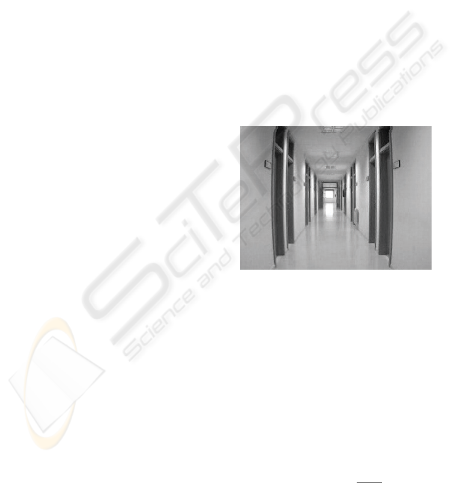
provide us to get a model of the scene. The experi-
mental set-up is as follows: To imitate arbitrary mo-
tions of a disabled person mounted in a wheelchair,
a mobile platform is manually displaced along a cor-
ridor with diffuse light and non-conditioned material
in an arbitrary (sometimes erratic) way . Kinematic
characteristics of the trajectories are unknown. The
mobile platform has a low-cost uncalibrated video
camera providing low-quality images, which are sam-
pled twice each second.
3.1 Perspective Models
Lines of the ordinary space provide the main features
for perspective models. The set of space lines through
an eventually mobile point (focus of the camera) is
a homogeneous compact manifold called a projec-
tive plane P
2
. Often, in architectural scenes, some
”meaningful lines” can be grouped in pencils through
each ”vanishing point”. Structural elements for a
perspective map of the scene are given by vanish-
ing points V
i
, perspective lines PL
j
and perspective
planes PP
k
. Vanishing points v
i
are the intersection
locus of at least four perspective lines PL
j
parallel in
the scene (three lines can converge in a corner which
is not a vanishing point in general). In complex archi-
tectural scenes there can be a lot of vanishing points,
due to the misalignment of walls or faades, in indoor
or outdoor scenes, respectively. For clarity purposes,
we restrict ourselves to simpler cases of indoor scenes
with at least three independent vanishing points.
In frontal views of a large number of architectural
simple scenes, there are three main vanishing points.
Typical frontal views have two fixed vanishing points
at infinite distance, labelled as v
x
and v
y
, correspond-
ing to the intersection of pencils of horizontal and ver-
tical lines, respectively. Usually, the vanishing point
v
y
is fixed. However, rotations of the camera give
displacements of v
x
, providing the main input for the
motion estimation. Furthermore, even for rectified
views, turning a corridor generates abrupt changes
in the identification of perspective elements involving
the localization of v
x
.
Figure 1: Perspective Model and Quadrilateral Map.
Collinear segments are grouped to obtain ”large”
lines
j
with a length (number of collinear mini-
segments) larger than a threshold selected by the user.
So, a collection of allowed lines
j
i
is obtained as
candidates for perspective lines through the vanishing
point v
i
. Candidate perspective lines are obtained by
an automatic grouping of segments, and a selection
of pencils Λ of lines which converge in a vanishing
point v
i
. Validation of v
i
is performed by minimiz-
ing
(
T
j
i
v
i
)
2
. After estimating each vanishing point
v
i
, candidate perspective lines are replaced by new
perspective lines to provide a ”coarse rectification”
linked to a globally coherent perspective representa-
tion of the scene; this step is necessary for correcting
views provided by the low cost video camera.
Each pair of vanishing points V
i
, V
j
∈ P
3
deter-
mines an horizon line L
∞,ij
= V
i
V
j
⊂ P
3
which is
computed by the cross-product V
i
∧V
j
; any point on
L
∞,ij
is also a vanishing point. Often, visual target
VISAPP 2006 - MOTION, TRACKING AND STEREO VISION
470
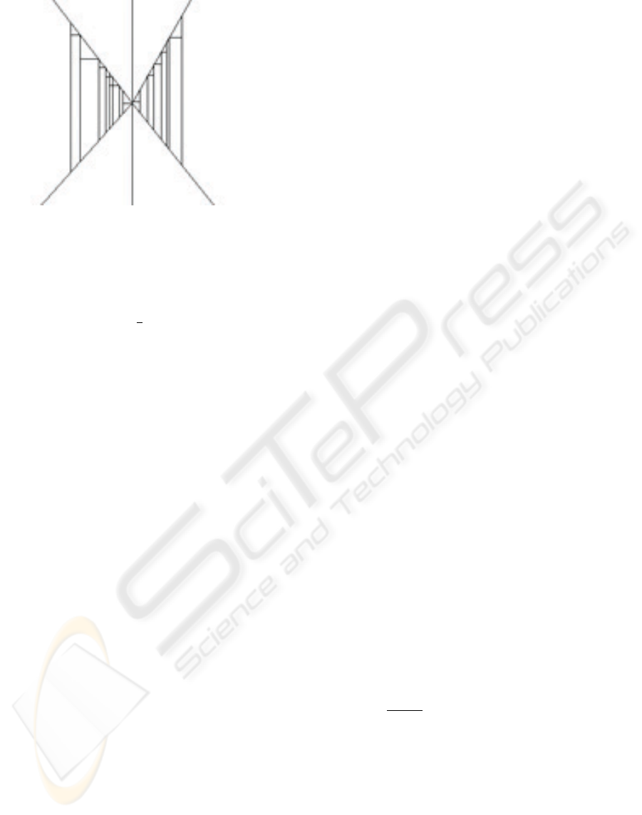
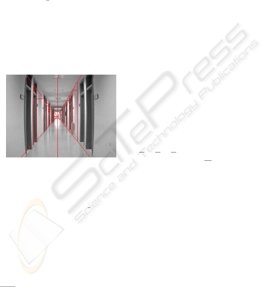
Figure 2: Perspective Model and Quadrilateral Map.
is located in L
∞,ij
, and the visual perception of ego-
motion in the image is represented by an apparent dis-
placement along the horizon line L
∞,ij
; in this case, it
suffices to track this displacement for egomotion es-
timation. To achieve a 2
1
2
reconstruction as general
framework for visual navigation, a projective repre-
sentation of the plane at infinity is required.
Three non-collinear vanishing points V
i
, V
j
, V
k
generate a plane at infinity in P
3
which is denoted
as Π
∞
without specifying the choice of vanishing
points. Thus, π
∞
can be taken as an invariant refer-
ence plane for motion estimation and tracking. Simi-
larly, pencils L
i
, L
j
, L
k
or perspective lines through
the vanishing points V
i
, V
j
, V
k
give a dual refer-
ence.
Let us denote by L
i
a pencil of perspective lines
through the vanishing point v
i
. Two pencils , L
i
, L
j
of coplanar perspective lines determine a perspective
plane which is denoted by L
i
+ L
j
. The perspec-
tive representation of an ordinary architectural scene
is visualized by means of three pencils L
h
, L
v
, L
d
of
horizontal, vertical and depth perspective lines. This
representation is a local version of the projective rep-
resentation, and it can be interpreted as a dual refer-
ence system for the projective plane which extends
the plane of each view. A perspective representation
of the scene in terms of perspective lines is more ro-
bust than representations based on points.
There are three basic perspective models which are
labeled as frontal, angular and skew depending on the
availability of one, two or three vanishing points at fi-
nite distance. If there is no vanishing point at finite
distance we have a parallel projection, which is not
a perspective model, properly said. A corridor scene
(resp. room scene) is represented by a frontal (resp.
angular) perspective model, whereas in turning a cor-
ner of a corridor an angular perspective model pro-
vides the transition between two frontal perspective
model. In outdoor architectural scenes, the localiza-
tion of the camera gives skew perspective models for
the transition between angular perspective models.
3.2 Quadrilaterals Map
The low quality of conventional video cameras and
the bad illumination conditions, impose serious re-
strictions for achieving robust results in real-time, in-
cluding an on-line localization for a mobile platform.
Visual perception of rectangular regions is more ro-
bust than corners surrounding them. In frontal per-
spective models one has at least a vanishing point v
z
at finite distance. In this model, rectangular regions
are ideally perceived as trapezoids, i.e., as quadrilat-
erals with two parallel vertical edges. To simplify the
tracking of quadrilaterals, we restrict ourselves to hor-
izontal and vertical segments. Hence, the first task is
the construction and tracking of two trapezoidal maps
linked to v
z
. There are two extremal perspective
lines PL
M,z
, PL
m,z
through v
z
with maximal M
and minimal m slope and affine equations
M,z
=0,
m,z
=0, respectively. Both perspective lines decom-
pose the plane in four signed regions, depending on
the sign evaluation for affine equations at each point.
Vertical (respectively, horizontal) segments contained
in regions (+, −) and (−, +) (respectively, in regions
(+, +) and (−, −)) are extended till to arrive to ex-
tremal perspective lines. So, we generate two trape-
zoidal maps T
z,ver
and T
z,hor
linked to the vanish-
ing point v
z
. Both trapezoidal maps are bounded
by extremal perspective lines with vertical and hor-
izontal parallel segments, respectively. After retrac-
ing extremal perspective lines, each trapezoid of a
trapezoidal map linked to a vanishing point is char-
acterized by three points. For each oriented trapezoid
T
i,j
∈T
z,j
with j = ver or j = hor, we associate
in a canonical way a pair of bivectors representing the
trapezoid uniquely; a bivector is the cross-product of
two ordinary vectors.
The same argument is applied for angular and skew
perspective models, but by replacing the trapezoid by
a general quadrilateral, i.e is the image of a rectan-
gle by an affine transformation, whose opposite edges
are supported on perspective lines through the same
vanishing point. Two coplanar pencils Λ
i
and Λ
j
of
projective lines through the vanishing points V
i
, V
j
give a quadrilateral map. The quadrilateral map Q
is supported by a plane through the vanishing line
L
∞,ij
:= V
i
V
j
. Data structures for a quadrilateral
map Q are supported on visible segments lying in two
coplanar pencils L
i
, L
j
of perspective lines. Thus,
for a typical architectural scene, we have three fam-
ilies of maps of quadrilaterals Q
12
, Q
13
, Q
23
linked
to pencils of perspective planes through the vanish-
ing lines L
∞,12
, L
∞,13
, L
∞,23
. A sheaf depending
on two (resp. three) parameters is called a net (resp.
web). Hence, by packing quadrilateral maps a web of
quadrilaterals is obtained.
The basic cell of a a quadrilateral map is
given by an ordered quadrilateral Q
ij
with edges
A DIFFERENTIAL GEOMETRIC APPROACH FOR VISUAL NAVIGATION IN INDOOR SCENES
471
a
i1
, b
j1
, a
i2
, b
j2
. Edges are supported on two pairs
of lines lying on pencils of perspective lines; so we
have a
i1
⊂
i1
∈L
i
, b
j1
⊂
j1
∈L
j
and so on. The
oriented area for the quadrilateral Q
ij
is given by the
bivector
A(Q
ij
)=
1
2
[a
i1
× b
j1
+ a
i2
× b
j2
] (1)
In particular, if Q is a map of quadrilaterals for a
frontal perspective model, then each quadrilateral is a
trapezoid. Quadrilateral maps are referred in projec-
tive representation with respect to the common van-
ishing point (corresponding to the preservation of ver-
tical direction), and a rotation of the horizon line op-
posite to the vanishing point. In the general case,
rotation is computed following the methodology de-
scribed in (Jelinek and Taylor, 2001).
Figure 3: Perspective Model and Quadrilateral Map.
Turning a corridor implies severe alterations in
maps of quadrilaterals, and it is necessary to have a
3d model for integrating turning quadrilateral maps in
a common framework. The proposed common frame-
work for the on-line management of 2
1
2
d information
is given by a map of cuboids. A cuboid is given by
the cross product of three linearly independent vec-
tors; a parallelepiped is a cuboid given by the triple
product of three orthogonal vectors. In architectural
scenes, edges (respectively, faces) of cuboids are sup-
ported on perspective lines (respectively, planes). The
intersection of two adjacent cuboids is a face of one of
them. Modeling of cuboid maps C is similar to mod-
eling of trapezoidal maps, but increasing the dimen-
sion in a unity. So, instead of considering pencils Λ
i
of lines through vanishing points V
i
, it is necessary to
consider pencils L
k
of planes through vanishing lines
V
k
V
. Computer management is also similar, but by
replacing quadtrees by octrees. To avoid excessive
subdivisions, only non-empty cellules are subdivided
depending on the identification of visible perspective
elements in the 3d scene. Furthermore, only local in-
formation is preserved in short memory whereas some
part of the scene is visible. In this way, a verification
of global coherence is avoided in updating 3d models.
4 LIE OPERATORS FOR
EXPANDING/CONTRACTING
MAPS
Motion estimation from optical motion is not well-
determined. It is necessary to add constraints, predic-
tions and measurements about the scene or the mo-
tion, which must be estimated, validated and updated.
In this section, a differential model is provided for a
simultaneous evaluation of the motion and the scene
structure from the updating of perspective represen-
tation of the scene. The key tool is the introduction
of simple transformations between perspective maps
which can be read in terms of maps of quadrilaterals
and cuboids. Some additional concepts are needed for
showing the main steps for both operations
4.1 Vector Fields for Motion
Estimation
A smooth vector field X is a section of the tangent
bundle T R
3
R
3
× R
3
, i.e., a representation of the
velocities field at each point. Hence, it is given by
a
∂
∂x
+ b
∂
∂y
+ c
∂
∂z
, where a, b, c are smooth functions
or more synthetically as
a
i
∂
∂x
i
.
The optical flow is a 2d vector field θ which is the
projection of the true 3d motion field. The egomotion
is a piecewise smooth vector field ξ providing a esti-
mation of the optical flow along a temporal sequence
of views with integral curve parametrized by λ.
Our differential geometric approach to the estima-
tion of the 3d motion vector field requires 1) the es-
timation of the 2d egomotion vector field ξ, the ex-
pression of 2d optical flow θ from the 2d egomotion
vector field ξ and the lifting of θ to the 3d motion field
by using the updating of the perspective model of the
indoor scene.
4.2 Differential Forms for the
Perspective Representation of
the Scene
A differential form ω is a section of the cotangent
bundle Ω
1
R
3
:= HOM(T R
3
,ε
1
R
3
) R
3
×R
3
where
ε
1
R
3
:= R
3
×R is the trivial vector bundle of rank 1 on
R
3
. A differential form ω ∈ Ω
1
is given by
b
i
dx
i
.
The evaluation ω(X) of a differential form on a field
VISAPP 2006 - MOTION, TRACKING AND STEREO VISION
472

gives a real number. Similarly, Ω
1
c
denotes the first
degree differential forms with compact support.
The canonical bases dx
1
,dx
2
,dx
3
and
∂
∂x
1
,
∂
∂x
2
,
∂
∂x
3
are dual between them, i.e.,
dx
i
(
∂
∂x
j
)=δ
ij
(delta de Kronecker) for 1 ≤ i, j ≤ 3.
In particular, dz vanishes
∂
∂x
, and
∂
∂y
. Thus, in an
ideal euclidian model where z represents the depth,
it suffices to make adjustments with respect to the
component c of
∂
∂z
. Unfortunately, the perception
model of any video camera is not euclidian. Thus,
some additional considerations are required.
A map of Segments (resp. Quadrilaterals, resp.
Cuboids), is given as the support of a pencil of 1-
degree (resp. a net of 2-degree, resp. a web of 3-
degree) differential form with compact support ω ∈
Ω
k
c
(R
3
) of degree k for k =1(resp k =2, resp.
k =3. The choice of compact support for differ-
ential forms is justified by practical and theoretical
reasons: the objects to be tracked (quadrilaterals) are
compact and the need of representing volumetric el-
ements by ”non-trivial” models from the cohomolog-
ical viewpoint. To fix ideas, a static simple corridor
scene is modeled in a frontal perspective view with
vertical and horizontal trapezoidal maps correspond-
ing to lateral walls and floor-roof, respectively. Pen-
cils of lines belonging to each trapezoidal map verify
incidence conditions with respect to vanishing points.
For example, the vertical left trapezoidal map is deter-
mined by two pencils of lines through the vanishing
points v
y
for parallel vertical lines and v
z
for depth
map. Similarly, the horizontal lower trapezoidal map
is determined by two pencils of lines through the van-
ishing points v
x
for parallel horizontal lines and v
z
for depth map.
The real motion of the mobile platform generates
an apparent displacement of the vanishing points v
x
and v
z
(vertical direction is preserved). The apparent
displacement of vanishing points generates displace-
ments of vertical and horizontal quadrilateral maps
in each view. The displacement is controlled by 1)
a transversal direction to the vertical trapezoid given
a perspective horizontal line passing through v
x
for
vertical trapezoidal map; and 2)a transversal direc-
tion to the horizontal trapezoid given a perspective
depth line passing through v
z
for horizontal trape-
zoidal map.
The exterior differential of a k-degree differential
form gives a (k +1)-degree differential form. In par-
ticular, if we would have the simplest representation
for the left vertical trapezoidal map given by the 2nd
degree differential form ω
vert
= a
vert
(x, y, z)dz∧dx
, then its differential dω
vert
=
∂a
vert
∂y
dx ∧ dy ∧ dz
would give a cuboid map relative to the lacking or-
thogonal direction. Similarly, if we would have the
simplest representation for the lower horizontal trape-
zoidal map given by the 2nd degree differential form
α
hor
= b
hor
(x, y, z)dy ∧ dz , then its differential
dα
hor
=
∂b
hor
∂x
dx ∧ dy ∧ dz would give a cuboid
map relative to the lacking orthogonal direction. As
both cuboid maps must be the same, one has a struc-
tural constraint dω
vert
= dα
hor
. Hence, it suffices to
consider only a trapezoidal map. By visibility reasons
it is more practical to restrict to a left vertical trape-
zoidal map T , e.g., generated by the intersection of
pencils of projective lines through v
z
and v
y
.
4.3 Lie Contraction/Expansion
Operators
Even when prior information about the scene is avail-
able, optical flow is not easy to compute due to noise,
partial occlusions, etc. Quadrilateral are easier than
points for tracking, and they provide a support for dif-
ferential forms with compact support. Each mobile
vector, bivector or three-vector (with support contain-
ing a segment, a quadrilateral or a cuboid) is the dual
of a 1, 2 or 3-degree differential form in a point. Ho-
mologue elements are linked along the motion by the
directional or Lie derivative.
The Lie (directional) derivative of a k-th degree dif-
ferential form ω is the k-th degree differential form
defined by L
ξ
ω(x)=
d
dλ
(f
∗
λ
ω)(x) |
λ=0
; let us re-
mark that
d
dλ
is a linear operator.
The motion field θ corresponding to the apparent
motion of homologue elements along the sequence of
views is topologically modeled by a local diffeomor-
phism f
λ
(ξ) arising from the integration of the vec-
tor field ξ. The linearization of the diffeomorphism
f
λ
(ξ) (differential evaluated at origin) gives an ele-
ment of the general linear group GL(3; R). Its semi-
direct product with the translation gives the affine lin-
ear map between homologue elements along the se-
quence of temporal views. The estimation of θ is
performed from the comparison between homologue
trapezoids or, more generally, quadrilaterals in terms
of Kalman filters (see below).
The flow conservation’ equation f
∗
λ
(dω)=d(f
∗
λ
ω)
implies the conservation of homologue 2d rigid el-
ements (trapezoidal or quadrilateral maps) along the
temporal sequence of views. The lifting of the flow
conservation to the 3d ambient space implies the
preservation of homologue 3d rigid elements along
the motion. The homologue rigid elements are visu-
ally perceived as cuboids corresponding to different
views of the same rectangular parallelepiped. Hence,
they are related between them through affine transfor-
mations which must be estimated on line.
The exterior differentiation commutes with the Lie
derivative which is a linear operator
d
dλ
. Thus,
d(L
X
ω)=L
X
(dω) for every ω ∈ Ω
k
M
, which can be
expressed as dL
X
= L
X
d in a more synthetic way.
A DIFFERENTIAL GEOMETRIC APPROACH FOR VISUAL NAVIGATION IN INDOOR SCENES
473

The piecewise-linear expansion of the 2d quadri-
lateral map Q (given in particular by a the trapezoidal
map T ) to a cuboid map C is locally given by the sup-
port of the exterior product ω ∧ η where η is a dif-
ferential form supported on lines through the lacking
vanishing point v
x
.
The apparent displacement of rigid elements iden-
tified on the quadrilateral map Q (respectively, cuboid
map C) is modeled by the Lie derivative of the 2-
degree differential form ω (respectively, the 3-degree
differential form dω) along the motion field ξ.
Given a differentiable manifold M , for any vec-
tor field X ∈X(M) on M and for any k +1-
degree differential form ω ∈ Ω
k+1
M
, the contrac-
tion of ω along the vector field X, denoted as i
X
ω
is defined as the k-th differential form given by
i
X
ω(X
1
,...,X
k
):=ω(X, X
1
,...,X
k
) for any
vector fields X
1
,...,X
k
∈X(M)
The piecewise contraction of the cuboid map C to
the three quadrilateral maps Q
ij
, for 1 ≤ i<j≤ 3
is locally given by the Lie contraction of Ω along the
Lie vector field ξ of the egomotion.
The simplest local representation of mobile maps
of cuboids (respectively, quadrilaterals) is given
by orthographic three-dimensional reconstructions,
where basic pieces are rectangular parallelepipeds,
which are distorted by perspective effects. By means
a projective transformation, it is possible to send the
three vanishing points to the infinity, to construct a
parallepiped model for the scene with euclidian infor-
mation (for scaled orthographic resulting representa-
tion), solve the contraction/expansion, and to perform
the inverse transformations. However, this would
have a high computational cost, and it would be some
difficult to obtain a real-time implementation. Thus,
it is important to develop a forward estimation of
egomotion directly supported on maps of homologue
quadrilaterals. To fix ideas, let us restrict to the trape-
zoidal map T corresponding to v
y
and v
z
5 MOTION ANALYSIS
The general problem is which kind of information
about the motion vector field Θ can be extracted from
the egomotion vector field ξ in an indoor scene. Ho-
mologue quadrilaterals allow to evaluate magnitude
and direction of motion field. Usual differential mod-
els for ego-motion estimation are based on optical
flow. Some troubles are related with aperture prob-
lem, noise for geometric features, indeterminacy or
ambiguity about homologue elements, between oth-
ers. In our case, the differential formalism allows to
reduce the estimation/tracking of a trapezoid to the es-
timation/tracking of two segments supported on per-
spective lines through v
z
. An important issue con-
cerns to the estimation of 1D (perspective lines) or
2D data (trapezoids, quadrilaterals), and the adapt-
ability to changing conditions. Thus, we develop an
approach able of supporting estimation and tracking
of positive dimensional elements.
After modeling, main problems concern to 1) the
prediction from the current localization, 2) the iden-
tification of homologue quadrilaterals along sampled
views of a video sequence, 3) model’s validation and
4) prediction updating.
5.1 Dynamic Modeling
A discrete dynamical system can be represented by
a state equation s
i
= ψ
i,i−1
s
i−1
w
i
where s
i
is the
state vector at instant i, ψ
i,i−1
is a linear matrix, and
w
i
is the random noise representing a perturbation on
the system. To simplify, one supposes a white noise,
i.e. E[w
i
]=0,E[w
i
w
T
i
]=Q
i
where the covari-
ance matrix Q
i
is usually determined in a heuristic
way. If we suppose that data are not correlated be-
tween them, then a diagonal matrix can be chosen for
Q
i
. To avoid heuristics, a choice based on triangu-
lar matrices allows to maintain dependence relations
between nested elements.
5.2 Dynamical Estimation of the
Trapezoidal Map
In this subsection, wand adaptation of (Faugeras,
1993) is developed for estimating and measuring the
trapezoidal map as a discrete dynamical system. We
have followed an incremental estimation approach:
• Static states for each trapezoid of the trapezoidal
map T are represented by a 2d vector t
i
corre-
sponding to a coordinate of a corner, and the width
of trapezoid.
• Kinematic states s
i
are given by a 4d vector (t
i
,
˙
t
i
)
where
˙
t
i
is the temporal variation of t
i
.
• The plant’s or state’s equation is s
i
= ψ
i|i−1
s
i−1
+
w
i
where ψ
i|i−1
s
i−1
is a triangular matrix respon-
sible for the kinematic coupling and w
i
is a white
noise with E[w
i
.w
T
i
]=Q
i
. To begin with, ψ
1|0
=
I
2
I
2
0 I
2
where I
2
is the 2 × 2 identity matrix.
• The measurement equation is given by m
i
=
H
i
s
i
+ ν
i
with noise ν
i
. It gives as output the 4× 4
linear transformation H
i
for each trapezoid.
• Covariance matrix: Due to the lack of information
about estimated values, we take an initial covari-
ance matrix P
i
given by a 4 × 4 diagonal matrix
with high positive eigenvalues.
VISAPP 2006 - MOTION, TRACKING AND STEREO VISION
474

• The prediction of the covariance matrix before
comparing the 0-th (before motion) and the first im-
age is equal to P
1|0
= ψ
0
P
1
ψ
T
0
+ Q
0
where ψ
0
has
been estimated before, and Q
0
= E[w.w
T
] for the
i-th trapezoid.
5.3 Kalman Filtering
A Kalman filter (Faugeras, 1993) is a recurrent linear
technique for solving a dynamic problem by the least
squares method, allowing to integrate noised mea-
sures. Measures can be corrupted by white noise, and
must be corrected without having all the measures. In
our case, we have adapted Kalman filtering to maps of
quadrilaterals, (Marion, 2002). The estimation based
on KF is performed without waiting to have all the
measures.
Typical steps of standard KF are given by initial-
ization, measurement, validation and updating of pre-
diction. The initialization has been already described
below.
5.3.1 Mahalanobis Distance for Updating
Measurements
Under uncertainty conditions, the covariance matrix
Λ
i
provides information about the dispersion of data,
and allows to compute the Mahalanobis distance
d
iM
(x,µ):=(x − µ)Λ
i
(x − µ)
T
of a vector x with
respect to the current mean value µ
. In our case, the
comparison between 0-th and first images gives an
initial measurement matrix H. From H, the covari-
ance matrix Λ
0
= HR
0
H
T
+ R
1
.
Along the iteration,d
iM
=(m
i+1
−
Hs
i
)Λ
−1
i
(m
i+1
− Hs
i
)
T
where m
i+1
is the
measure at time i +1with covariance matrix R
i
, and
Λ
i
= HP
i
H
T
+ R
i+1
.
5.3.2 Validation
If the computed Mahalanobis distance for the segment
representing the trapezoid, is lesser than a selected
threshold, then the estimation is accepted. Otherwise,
another trapezoid must be selected, and the process
re-starts.
5.3.3 Updating of the Kalman Filter
The information is updated in the standard form as
follows: 1) Gain matrix: K
0
= R
0
H
T
(HR
0
H
T
+
R
1
)
−1
; 2) Updating of the state’s estimation: ˆs
1
0s
0
+
K
0
(m
1
− Hs
0
); 3) Updating of P
0
in
ˆ
P
0
=(R
0
+
H
T
R
−1
1
H)
−1
The process is iterated for all trapezoids contained
in the central part of the image with homologues eas-
ily identifiable in the precedent and consecutive view
of the sequence.
5.3.4 Extended Kalman Filter EKF
Most processes in real world are not linear. Hence, we
must adapt or extend KF (EKF) to the non-linear case:
In each step a linearization of the precedent estimated
state is performed. If the initialization is not enough
good or if the noise is high, then the convergence is
not guaranteed. In this case, it is necessary to modify
initial constraints or to perform a new processing of
the acquired information.
5.4 Estimation and Tracking of
Quadrilaterals
The pipeline for estimating and tracking quadrilater-
als is as follows
1. Grouping of mini-segments in long segments
2. Computation of intersections of lines supported by
long segments
3. Identification of putative perspective lines
4. Estimation of vanishing points
5. Retracing of ”true” perspective lines
6. Grouping of perspective lines in three pencils L
i
through vanishing points V
i
7. Maps of Quadrilaterals Q
ij
linked to each pair L
i
,
L
j
of perspective lines.
8. Identification of allowed simple events involving
changes in quadrilaterals (grouping or decomposi-
tions).
9. Representation of transformations involving inde-
composable quadrilaterals by triangular matrices.
10. Solving systems by successive reduction in trian-
gular matrices.
6 CONCLUSION
A geometric framework based on mobile perspective
models is superimposed to structured scenes. An on-
line updating of changing perspective models is per-
formed from quadrilateral maps by sampling two im-
ages each second. Expansions of maps of quadri-
laterals are constructed as maps of cuboids by using
differential constraints. A new representation of the
egomotion is provided in terms of Lie derivative of
the quadrilateral maps and the Lie contraction of the
cuboid map along the egomotion field ξ. The esti-
mation of the egomotion is directly computed on the
quadrilateral map by using an adaptation of Kalman
filtering. Some challenges for the next future are re-
lated with a) the implementation of a real-time mod-
ule for generating and tracking mobile perspective
A DIFFERENTIAL GEOMETRIC APPROACH FOR VISUAL NAVIGATION IN INDOOR SCENES
475

models will be developed, b) improve metric localiza-
tion from uncalibrated video sequences, c) identifica-
tion of mobile human beings in the scene compatible
with the motion mounted on the platform, d) evalua-
tion of behaviors to improve the interaction.
ACKNOWLEDGEMENTS
The authors acknowledge to the MAPA Project
and specially thanks to J.J. Fernandez-Martin and
J.I.SanJose Alonso for their partial finantial support.
REFERENCES
A. Pruski, M. E. and Morre, Y. (2002). Vahm: A user
adapted intelligent wheelchair. In IEEE Intl Conf on
Control Application (Glasgow, Scotland, UK). IEEE.
Cort
´
es, U., Annicchiarico, R., V
´
azquez-Salceda, J., Ur-
diales, C., namero, L. C., L
´
opez-S
´
anchez, M.,
S
`
anchez-Marr
`
e, M., and Caltagirone, C. (2003). e-
tools: The use of assistive technologies to enhance
disabled and senior citizens’ autonomy. In EU-LAT
Workshop on e-Health, pages 117–133.
Faugeras, O. (1993). Three-dimensional Computer Vision.
A Geometric Viewpoint. The MIT Press, Cambridge,
Mass.
J. Minguez, L. M. and Montano, L. (2004). An architec-
ture for snsor-based navigation in realistic dynamic
and troublesome scenarios. In Proc. IROS). IEEE.
Jelinek, D. and Taylor, C. (2001). Reconstruction of linearly
parametrized models from single images with cam-
era of unknown focal length. IEEE Trans. on Pattern
Analysis and Machine Intelligence, 23(7):767–773.
Levine, S. P., Bell, D. A., Jaros, L. A., Simpson, R. C., and
Koren, Y. (1999). The navchair assistive wheelchair
navigation system. IEEE Trans on Rehabilitation En-
gineering, 7 (4):443–451.
M. Gonzalo, J. Finat, M. A. and Aguilar, S. (2002). Dynam-
ical trapezoidal maps for coarse perspective model in
indoor scenes. In ISPRS’02, 1st International Confer-
ence on Enterprise Information Systems. ISPRS.
M. Rous, H. L. and Kraiss, K. F. (2001). Vision-based
landmark extraction using indoor scene analysis for
mobile robot navigation. In IEEE/RSJ International
Conference. IEEE.
Marion, G. (2002). Estimacin y Prediccin del Movimiento
Propio en Escenas de Interior mediante Filtros
Kalman. Master’s thesis, Valladolid.
Mazo, M. and et al (2002). Experiences in assisted mo-
bility: The siamo project. In Proc. IEEE Intl Conf
on Control Applications (Anchorage, Alaska), pages
766–771. IEEE.
P. Trahanias, M. Lourakis, A. A. and Orphanoudakis, S. C.
(1997). Navigational support for robotic wheelchair
platforms. In Proc. ICRA-IEEE. IEEE.
R. Simpson, E. LoPresti, S. H. and Nourbakhsh, I. (2004).
The smart wheelchair component system. J. of Reha-
bilitation Research and Development, 41:429–442.
Toedem
´
e, M. Nuttin, N. T. and Gool, K. V. (2004). Vision
based intelligent wheelchair control: the role of vision
and inertial sensing in topological navigation. J. of
Robotic Systems, 21(2):85–94.
Yanco, H. A. (1998). Integrating robotic research: a sur-
vey of robotic wheelchair development. In AAAI
Spring Symp. on Integrating Robotic Research (Stan-
ford, CA). IEEE.
Yuki, O. (2000). Corridor Navigation of a Mobile Robot us-
ing a camera and sensors-multiagent approach. The-
sis, UCLA University, Los Angeles, CA.
VISAPP 2006 - MOTION, TRACKING AND STEREO VISION
476
