
BUSINESS IMPROVEMENT THROUGH AUTOMATIC
WORKFLOW MODELING
Carlos R. Lopes, Jony T. Melo
Faculdade de Computação – Universidade Federal de Uberlândia (UFU)
Av. João Naves de Ávila 2121 – 38400-902 –Uberlândia/MG – Brasil
Keywords: Workflow, Modeling, Artificial Intelligence, Planning.
Abstract: Advances in Information Technology have created opportunities for business enterprises to redesign their
information and process management systems. The redesigned systems will likely employ some form of
workflow management system. This is not surprising since businesses in any segment, can benefit from
workflow management. Workflow management systems exactly enact business processes described in a
process description language. Despite the advertising claims of many companies, current workflow systems
require a software developer to construct the workflows using a process description language. In order to
make this task easier, in this paper we describe an algorithm for automatic generation of workflow that uses
Artificial Planning Techniques. Moreover, we present a case of study based on the implementation
developed.
1 INTRODUCTION
Fulfilling a complex goal usually requires the
participation of more than one individual; whether
that goal is the production of consumer goods, the
provision of services or the generation of
knowledge. This is a common fact in society,
companies, schools, hospitals etc. All these
organizations distribute their activities into a
sequence of tasks that can be seen as a process.
Business processes are carried out by actors, which
cooperate to produce desired results. These
processes can include several internal and external
actors such as customers, suppliers and business
partners.
Agility and reliability in the execution of
services as well as ever-higher quality are a
necessity in today’s world. This gives rise to the
necessity of team work, the management and reuse
of information, and the constant improvement of the
production processes. In this context, workflow tools
have an important role because they are associated
with the automation of processes. These tools had
their origin in offices-automation research in the
70’s when the main objective was to offer solutions
that enable the generation, the distribution and the
sharing of documents within organizations. During
the 80’s, influenced by groupware research and by
computer supported cooperative work (CSCW),
these workflow tools were transformed into
instruments for the work coordination team. The fast
growth of computer networks (Internet/Intranet)
during the 90’s enabled continued workflow-tool
evolution (Boyd, 2000).
Recently, interest in applying techniques of
Artificial Intelligence (AI) to traditional systems has
increased in order to solve common problems. There
is a special interest in the techniques that involve AI
Planning. These techniques are widely used in
specialized areas such as: space missions, robotics,
planning of military missions, control of elevators
etc (Russell and Norvig, 2003). Nevertheless, many
other areas could take advantage of the possibility of
automation offered by the application of AI Planning
technology. In this line, there is the PLANET
network, whose objective is to promote the
development and integration of this technology into
several areas. This entity was organized in small
units of coordination, called the Technical
Coordination Unit (TCU), which is responsible for
leading development in each area. One of the work
lines promotes the practical application of these
planning techniques and scheduling for workflow
systems. The proposal presented in this paper is
essentially based on the guidelines presented in the
227
R. Lopes C. and T. Melo J. (2006).
BUSINESS IMPROVEMENT THROUGH AUTOMATIC WORKFLOW MODELING.
In Proceedings of the International Conference on e-Business, pages 227-234
DOI: 10.5220/0001428402270234
Copyright
c
SciTePress

road map that guides research in this area (PLANET,
2003) and aims at integration between workflow
process modeling and planning tools.
Workflow tools are often used in companies,
which generally have uncertain and changing
environments. These changing environments are the
result of marked demands such as client exigencies,
competition or new governmental laws. In order to
satisfy these demands, two types of tools are
required. The first type of tool should be used to
model, to modify, to simulate and to optimize
automatically existing processes in agreement with
the business rules of the company. The second type
of tool should be used to execute, monitor and adapt
dynamically processes resulting from the
modifications generated by the first tool. These two
types of tools constitute the main structure of a
workflow application. In this article, emphasis is
given to the former tool. We claim that techniques of
AI Planning can increase the efficiency of process
modeling and produce sound models.
This article is structured as follows. In section 2, we
describe the main concepts related to workflow
modeling. Section 3 presents AI planning concepts.
Section 4 shows the architecture in which our
proposal of planning and workflow integration was
built. The work developed is presented and detailed
in sections 5 and 6. Finally, section 7 discusses
related research and section 8 draws the conclusions
of this article.
2 WORKFLOW MODELLING
We can analyze a workflow system by taking into
account its various functions which cover three main
areas: process modeling, execution, and
management. In this article, emphasis is given to
process modeling.
The modeling of a process begins by translating
features from the real world to the computational
environment, generating a formal model by means
of appropriate modeling techniques. A model must
contain all the important information about the
process, such as: start and finish conditions,
execution rules, users or agents, information or
documents to be manipulated, interaction with
external applications etc. Below we describe the
main components and features of a modeling task.
Activities: The main element in a workflow is an
activity which must be completed for the conclusion
of the process goal to take place. To execute an
activity an actor must assume a role related to this
activity. This actor can be a person, an application,
or a computerized agent.
Chaining of Activities: The activities in a
workflow can be organized in three different ways:
sequentially, in parallel or conditionally.
Sequentially means that as soon as one activity is
executed, the following is activated. The subsequent
activity cannot be initiated until the current one is
concluded. Activities executing in parallel are
activated simultaneously. They do not need to be
concluded at the same time, because they can follow
different criteria or they can demand distinct
operations.
Eventually, these parallel flows either converge and
become a sequential flow or reach the end of the
process. The conditional chaining appears when the
next activity to be executed is based on a decision.
This decision will be made based on information
contained in the process. Rules for conditional
chaining must be created during the process
modeling.
3 AI PLANNING
AI planning seeks to determine an orderly set of
actions that, when executed by one or more agents
from an initial state (that satisfies the start
conditions), results in a final state, which satisfies a
goal. The sequence of actions makes up a plan
(Russell and Norvig, 2003). The PLANET roadmap
subtly complements this definition by introducing
the process concept. A process is a description of an
ordered set of activities. A plan is a description of a
sequence of actions that lead to the fulfillment of an
objective, i.e., an instantiated process (PLANET,
2003). These definitions are complementary, and
they introduce the process as a set of all the valid
plans.
We have used the classical planning model as a
starting point for applying planning techniques to the
workflow domain.
The evolution of planning techniques has also
promoted the evolution of its representation by using
an appropriate language. Important milestones in
this evolution are STRIPS, the ADL language, and
more recently PDDL (Russell and Norvig, 2003).
Planning is defined by a tuple of three elements (A,
I, G). A describes a set of actions, I represents a
initial state, and G is a goal to be achieved. Let P be
the set of all propositions that represents facts in the
world. The current state, or world, is assigned to w
and represents the subset of satisfied propositions in
P so that w ⊆ P in the world. In STRIPS, an action is
ICE-B 2006 - INTERNATIONAL CONFERENCE ON E-BUSINESS
228
represented by a triple (pre(a), add(a), del(a)) whose
elements belong to the set of propositions P and
corresponds respectively to its preconditions and
effects – this last through the add and delete lists.
Action a is applicable in w if w ⊇ pre(a) holds. To
apply a in w, replaces w with w’ so that w’ = w -
del(a) + add(a). It is assumed that del(a) ∩ add(a) =
{ }. In every model, a sequence of actions is a plan if
the result of its execution achieves its goal.
4 SYSTEM ARCHITECTURE
Management of processes (in a Workflow) and AI
Planning are similar areas and there are many things
in common between these two disciplines. There are
more similarities than differences (PLANET,2003).
In order to have greater agility in the convergence of
these areas, we will work on available tools and
frameworks. The main objective therefore, will be to
integrate workflow tools (such as those in modeling
and execution) with algorithms of planning. As a
platform for the modeling of processes, we chose the
Enhydra (The Enhydra.org project is similar to
Apache, but with a focus in E-Business software )
JaWE an open-source graphical tool for modeling
workflow processes, which complies with WfMC
specifications supporting XPDL (XML Processing
Description Language) language as native format.
XPDL (WFMC, 2005) provides an XML file format
that can be used to interchange process models
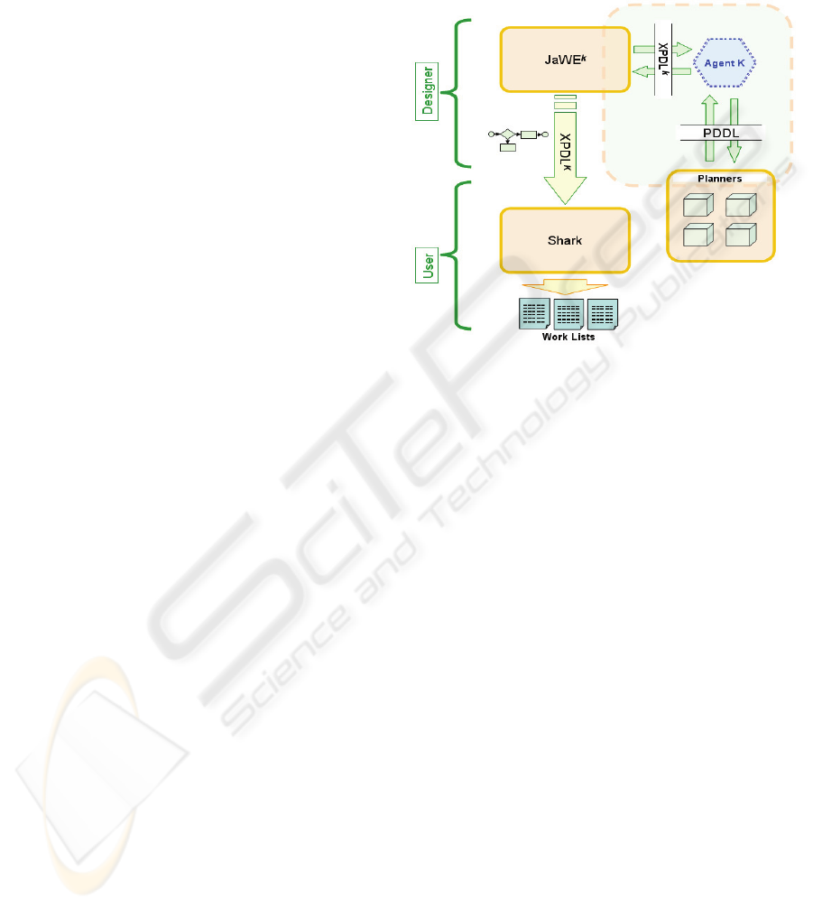
between tools. Figure 1 describes the main
components of our architecture.
Processes Modeling (JaWE
k
) : The JaWE tool
was modified to accept the new language of process
definition XPDL
k
that was derived from the original
language XPDL. Also, it was expanded with
necessary specifications for integrating AI Planning
tools.
Workflow Engine (Shark): The Shark tool was
modified in order to execute the new language of
process definition XPDL
k
. The workflow engine
instantiates the processes, generating work lists for
each step in the process. Shark also includes the
administration and monitoring of subsystems for
process instances. It is also possible to attribute to
automatic agents the execution of a specific
instance. Most of these features are specific to the
tool and comply with the WfMC specifications.
Planning Agent (Agent K): This agent has the
purpose of generating a workflow model through AI
planning. First, it converts the specifications of the
processes modeling language (XPDL for workflow)
to the domain definition language (PDDL for
planning). Later, it submits a requisition for plan
generation to the planning tool. Finally, it converts
the result (the plan) to the XPDL
k
format, returning
control to the modeling tool. We use the PDDL 2.2
(Edelkamp; Hoffman, 2004,) in this work.
Figure 1: AI Planning and Workflow integration scheme.
5 MODELING A WORKFLOW
USING PLANNING
TECHNIQUES
Based on the similarities between planning and
workflow modeling, we decide to investigate the
applications of techniques of planning in the
modeling of a workflow system. The planning agent
(Agent K) proposed in this paper manipulates data
described in a XPDL
k
format, which contains
information related to the activities of the process.
The data are manipulated in order to generate a
description of the activities in a PDDL format.
PDDL is a standard language used to define
problems to be solved by planners. Once we have a
PDDL description, it is possible to execute a
planning algorithm to generate a plan to satisfy a
goal. A goal in this domain refers to a disjunction of
situations that describe the end of the process (and
not only the satisfaction of a certain situation). For
instance, a credit request can end up being approved
or rejected. In both cases, the process is finished.
Our work shows that it is feasible to use planning
techniques in workflow modeling. In order to show
this we decided to use one or more planners that are
generally accepted for their efficiency and
BUSINESS IMPROVEMENT THROUGH AUTOMATIC WORKFLOW MODELING
229

popularity. Since a classical planner returns just one
plan for each execution, and considering that a
workflow process is a set of one or more plans, the
Agent K is also responsible for generating several
new plans in order to compose a complete workflow.
In this work, we use the FF–Fast-Forward
Planning System (Russell and Norvig, 2003).
5.1 Activities versus Operators
In the context of planning, operators represent
actions that can be executed by an agent. Each
operator is described by preconditions and effects.
Preconditions are those required to for action
execution. Effects correspond to the results of
executing an action. In the context of workflow, the
concept of an operator is not explicit in the modeling
language. Thus, we augment the language by
incorporating structures similar to production rules.
This allows the process designer to inform the
preconditions and effects related to a certain activity.
<Activity Id="Act4" Name=" Shipment Order">
<Description>
Sending the order products
</Description>
<Performer> Agent_1
</Performer>
<ExtendedAttributes>
<ExtendedAttribute
Name="RULE"
Value="
IF order_ready THEN order_shipped"/>
</ExtendedAttributes>
</Activity>
(a) XPDL Activity
(:action Shipment Order
:precondition (order_ready)
:effect (order_shipped)
)
(b) PDDL Action
Figure 2: Comparing XPDL activity with PDDL action.
It is up to the process designer to describe every
activity as well as its preconditions and effects. The
designer can also establish relations among activities
through connections, which represent flows from
one activity to another. The connections are called
transaction constraints. It is possible to associate
logical rules for their activation. However, there is
no direct relationship of cause and effect required
for the planning algorithm. In terms of planning, all
that is needed is the information contained in the
production rules. The users can use visual tools, like
JAWE, to create activities easily.
Figure 2 describes an activity using XPDL and
PDDL. The production rules are characterized by
preconditions and effects. Their syntax must closely
follow that of FOL. This makes it easy to convert a
XPDL description into PDDL.
The set of production rules associated with a
process is represented by L
r
. Each element of L
r
is
denoted by (c,e) where c is a clause that represents
conditions and e is a clause that represents effects.
Definition 1: Every activity is a tuple A =
(D,T,R) where D is the activity description,, T
represents a set of ordered pairs that correspond to
transitions between activities (T
⊆
(A
×
A)) and R is
the set of all valid rules for the activity (R
⊆
L
r
).
Prior to planning execution, each activity must
have values for D and R. After planning execution,
the planner agent returns a value for T in all the
activities required for the process.
5.2 Connections between Activities
In classical planning, an action is connected to
another in a sequential way. In the modeling of
processes, an activity can also be sequentially
connected to another. However, other compositions
may exist, which are either the result of decision
making or parallelism. These compositions are
characterized by ramifications.
There are two kinds of ramifications: splitting
(AND-Split and OR-Split connections) and joining
(AND-Join and OR-Join connections). Splitting
ramifications from the actual activity can lead to a
conditional (OR-Split) or parallel execution
(AND-Split). In a parallel execution, two or more
activities are enabled at the same time by the
workflow engine. A conditional ramification implies
a choice of a path to be followed. It means that only
one activity from the ramification of the current
activity will be enabled by the workflow engine. The
joining ramifications work as follows. An OR-Join
needs to be reached only by a branch from the
ramifications while an AND-Join requires to be
reached by every one of its branches. This means
that, an activity with an OR-Join ramification is
enabled when at least one of the previous activities
has been executed and that an activity with an
AND-Join ramification is enabled when all the
previous activities have been executed.
Figure 3 depicts the three combinations which
are permitted in the context of this work. A parallel
flow allows the simultaneous execution of two or
more activities from an AND-Split connection. Later,
the flow will converge to an AND-Join connection.
A conditional flow implies that only one edge will
be enabled. Later the flow will converge to an
ICE-B 2006 - INTERNATIONAL CONFERENCE ON E-BUSINESS
230
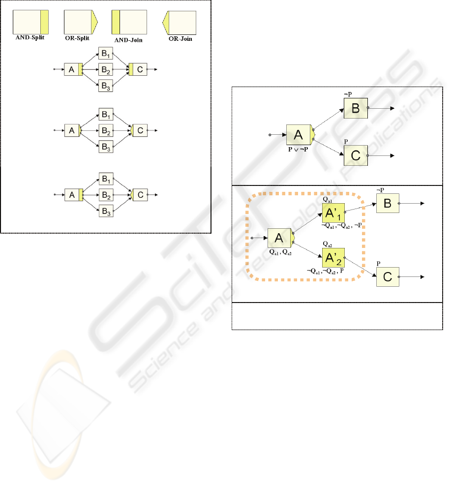
OR-Join connection, which means that it needs to be
reached by only one edge.
Finally, the flow parallel with the end selection
allows the simultaneous execution of two or more
activities. However, the convergence point must be
reached by at least activity.
a) Parallel
b) Conditional
c) Parallel with End Selection
Figure 3: Model of Branching Activities.
5.3 Mapping Activities into
Operators
There is a problem when mapping activities into
operators. Due to the possibility of flow splitting,
direct mapping is not feasible. Take the process of
credit approval. Once a credit request is completed,
an agent should execute an activity A to determine
whether the client has credit or not. Using direct
mapping, it would be impossible for a classical
planner to find a plan. This happens because the
effects of this action (Checking the credit) are
inconsistent and the result may be either credit
approval or credit rejection. In order to overcome
this obstacle, we propose the decomposition of
activity A into subactivities, one for each possible
independent effect. This decomposition is valid only
at planning time. Figure 4b shows the decomposition
of activity A into two subactivities, one for each
disjunctive effect (P and
¬
P).
Subactivity A’
1
allows the enabling of activity
B; and subactivity A’
2
makes possible the execution
of activity C. In this situation, A effects are replaced
by a list of effects that make it possible to establish a
causal link between A and A’ (In our example the
causal link is established by the clauses Q
a1
and Q
a2
).
In each subactivity, the disjunctive effect of the
original activity and other terms that correspond to
the negation of the causal link appear. This is done
so that the planner does not take one of the
subactivities into account without considering the
main activity.
The reasoning is similar to OR-Join activities.
In this situation, the subactivities must occur before
the main connection. A causal link is established
between the effect of the subactivity and the
precondition of the decomposed activity. Each
element of the disjunction makes up the precondition
of each subactivity.
a) Original Mapping
b) Decomposition
A = Checking Credit C = Credit Approval
B = Credit Rejection P = {true= has credit,
false= has no credit}
Figure 4: Decomposing activities OR-Split.
5.4 Workflow Planning
Once the activities are modeled correctly and once
the OR-activities are decomposed by the Agent K,
the next step consists in generating a description in a
PDDL format and in taking it to a planner.
A planner returns a plan, which is a sequence of
actions from an initial state to a state that satisfies
the goal. In the simplest case, modeling does not
include OR-activities. Therefore, all the activities
may be either sequential or have some degree of
parallelism. Figure 5 depicts the algorithm for
extracting a model from a plan.
BUSINESS IMPROVEMENT THROUGH AUTOMATIC WORKFLOW MODELING
231
extract_model(P){
01: for i=1 in (length(P)-1) do
02: A = elements_in(P);
03: if effect(A[i]) ∩ precond(A[i+1]) ≠ ∅
04: then
05: M := M ∪ pair(A[i],A[i+1]);
06: else
07: k = i + 1;
08: while k <= length(P) do
09: k = k + 1;
10: if effect(A[i]) ∩ precond(A[k]) ≠ ∅
11: then
12: M := M ∪ pair(A[i],A[k]);
13: exit_while;
14: end if
15: end while
16:
17: h = i + 1;
18: while h > 0 do
19: h = h – 1;
20: if effect(A[h]) ∩ precond(A[i+1])≠∅
21: then
22: M := M ∪ pair(A[h],A[i+1]);
23: exit_while;
24: end if
25: end while
26:
27: end if
28: end for
29: return M
}
Figure 5: Algorithm for extracting a Model from a Plan.
6 CASE STUDY: A WORKFLOW
FOR MANAGING
COMPLAINTS
In order to show the efficiency of our algorithms, we
implemented SisMAP, a system for automatic
modeling of workflow based on Planning. As a case
study, we used the modeling of a process related to
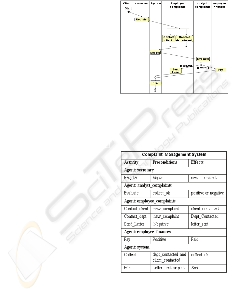
the management of complaints. The diagram of
activities of this process, following the UML syntax,
is described in Figure 6.
The process starts with the filling of a
complaint. Next, this complaint is sent to an internal
area, which is responsible for contacting the
customer in order to obtain more details. Moreover,
in parallel, the department involved with is
contacted. Based on the information resulting from
these two activities that occur in parallel, a decision
is made whether to pay to client or to send a letter to
the customer. Notice that this process contains a
decision node and parallelism of activities, which
represent challenges in automatic modeling of
workflows.
Figure 6: Diagram of activities “management of
complaints”.
The first step in modeling a workflow using SisMAP
consists of describing all activities with their
preconditions and effects. The description of all
activities is specified in Table 1.
Table 1: Description of process’s activities.
It is not necessary to describe the parallelism of
activities, which are, in this case, the activities
contact_client and contact_department. SisMAP can
automatically identify parallelism of actions and
incorporate them into a model. The decision node,
an OR-activity, is described by a disjunction of
ICE-B 2006 - INTERNATIONAL CONFERENCE ON E-BUSINESS
232
effects. In our case, the activity evaluate produces a
disjunctive effect: positive or negative.
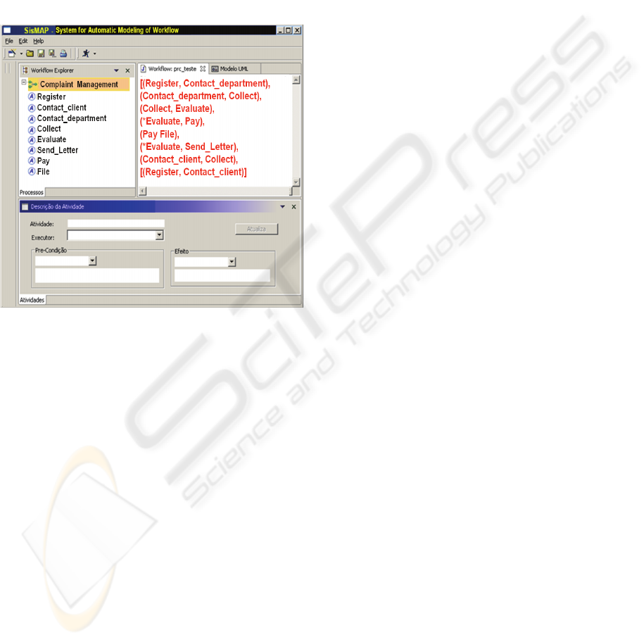
After finishing the description of activities, we
run the planner. The result of its execution is the
model depicted in Figure 7 (in the upper panel),
which is made up by pairs of actions connected to
each other. The model achieved is the same
described in Figure 6. In this way, we have a system
that is quite capable of generating sound models.
The model resulting from the planning can be easily
converted to XPDL language.
Figure 7: SisMAP Process Result.
7 RELATED WORK
In recent years, many works have been presented
with the perspective of integrating workflow
techniques and planning. A recent milestone in this
research field was the work presented by Myers and
Berry (1998) in which a study of the
correspondences between workflow and AI Planning
and Scheduling is accomplished. The authors also
present the possible contributions brought about by
the adoption of AI techniques.
Later, as a result of this research, they
developed a workflow system with reactive control
based on IA, called SWIM (Berry; Drabble, 1999).
The idea was intended to extend the workflow
paradigm so as to react to the dynamic environments
with some uncertainty. A drawback, according to the
authors, was that the automatic creation of processes
turned out to be a problem.
Another proposal uses techniques of
hierarchical and conditional planning to project
control programs that are used in automation
processes and manufactures (Castillo et al, 2003). In
this case, the planning is used to generate a control
program with hierarchical and modular
characteristics. There is a strong similarity between
the result obtained in this process and the generation
of workflow processes.
Some proposals (especially Ad-Hoc category)
aim to give flexibility to workflow execution. The
Ad-Hoc category does not have a previously defined
execution sequence. In this line, the work presented
by Bezerra and Wainer (2003) is an important
contribution. They use violations of restrictions to
define partial workflows, that is, workflows that do
not have a complete definition. Therefore, they must
be planned dynamically.
The proposal of Aler et al (2002) is closely
related to our work. The authors describe
SHAMASH, a tool for modeling processes whose
features include: the definition and use of
organization standards, automatic generation,
optimization and simulation of models. Their
architecture makes use of production rules to define
the relationship between activities and simulation
conditions as well as their optimization by using a
RETE algorithm. The best workflow model is
obtained through a search in a space of states
generated by a simulation machine that applies the
production rules created in the definition. Firstly, a
user defines activities using the authorship module.
Secondly, the activities are translated into a PDDL
format. Finally, a planner generates a plan (a
sequence of activities), which is translated to the
SHAMASH context. The nonlinear planner
PRODIGY4.0 is used to generate these plans. The
authors concluded that this scheme allowed the users
to focus on process requirements. It is up to the
planner to produce the most efficient model.
Our proposal shows the transformation of
workflow activities into planning operators in a
more consistent way. We also developed an
algorithm to obtain from classical planners a
workflow that contemplates decision nodes and
consequently conditional paths.
8 CONCLUSION
In this article, we provide ways to meet one of the
current demands of workflow tools by using
planning techniques, which is related to the
modeling of processes. When there are many
activities and levels of variables in a process model,
the modeling work − done by the human planner
aided by current tools − is hard and subject to
mistakes in process definition. It is also possible to
achieve inefficient processes. By using good
BUSINESS IMPROVEMENT THROUGH AUTOMATIC WORKFLOW MODELING
233

planning methods, sound plans can be achieved
quickly and with safety. These plans make up the
business processes.
Our proposal differs from others because it
shows the transformation of workflow activities into
planning operators in a more consistent way. We
also developed an algorithm to obtain from classical
planners a workflow that contemplates decision
nodes and consequently conditional paths.
We are investigating other planning techniques,
especially those related to dynamic planning. Many
algorithms have been developed for dynamic
environments, which we aim to integrate in the
workflow context, mainly in the management of
exceptions.
REFERENCES
Aler, R., Borrajo, D., Camacho, D., Sierra-Alonso, A.,
2002, "A knowledge-based approach for business
process reengineering, SHAMASH", Knowledge
Based Systems, 15(8):473-483, 2002.
Berry P.M., Drabble B., 1999, “SWIM: An AI-based
System for Workflow Enabled Reactive Control”
Proceedings of the IJCAI Workshop on Workflow and
Process Management, IJCAI-99, August 1999.
Boyd, S., 2000, “Workflow’s Third Wave: Process
Mediation of eBusiness”, Fujistsu’s White Paper at
http://www.i-flow.com, October.
Castillo, L., Fdez.-Olivares, J., González, A., 2003,
“Integrating Hierarchical and Conditional Planning
techniques into a software design process for
Automated Manufacturing”, 13
Th
International
Conference on Automated Planning & Scheduling
(ICAPS), Workshop on Planning under Uncertainty
and Incomplete Information.
Edelkamp, S.; Hoffman, J., 2004, “PDDL2.2: The
language for the classical part of the 4th international
planning competition”. Technical Report 195, Albert-
Ludwigs-Universitat,Freiburg, Germany, 2004.
Myers, K.L. and Berry, P.M., 1998, “Workflow
Management Systems: An AI Perspective”, Technical
Report, Artificial Intelligence Center, SRI
International, Menlo Park, CA (USA), 1998.
Planet, 2003, “PLANET Workflow Management R&D
RoadMap”, www.planet-noe.org, 2003, September
30
th
.
Russell, S. and Norvig, P., 2003, “Artificial Intelligence –
A Modern Approach”, 2
nd
ed,. Prentice Hall
Wainer, J. and Bezerra, F.L., 2003, "Constraint-based
flexible workflows", In: 9th International Workshop
on Groupware, CRIWG 2003, Autrans, France, pp.
151-158.
WFMC - Workflow Management Coalition, 2004, “The
workflow reference model”, http://www.wfmc.org,
2004, June.
WFMC - Workflow Management Coalition, 2005, “XML
Process Definition Language", Document Number
WFMC-TC-1025,http://www.wfmc.org, 2005,
October.
ICE-B 2006 - INTERNATIONAL CONFERENCE ON E-BUSINESS
234
