
HDL LIBRARY OF PROCESSING UNITS FOR GENERIC AND
DVB-S2 LDPC DECODING
Marco Gomes
1,2
, Gabriel Falcão
1,2
, João Gonçalves
1,2
, Vitor Silva
1,2
, Miguel Falcão
3
, Pedro Faia
2
1
Institute of Telecommunications, University of Coimbra, Coimbra, Portugal
2
Department of Electrical and Computer Engineering, University of Coimbra, Coimbra, Portugal
3
Chipidea Microelectronica SA, Porto, Portugal
Keywords: LDPC, HDL, DVB-S2, Iterative Decoding, Scheduling, Tanner Graph.
Abstract: This paper proposes an efficient HDL library of processing units for generic and DVB-S2 LDPC decoders
following a modular and automatic design approach. General purpose, low complexity and high throughput
bit node and check node functional models are developed. Both full serial and parallel architecture versions
are considered. Also, a dedicated functional unit for an array processor LDPC decoder architecture to the
DVB-S2 standard is considered. Additionally, it is described an automatic HDL code generator tool for
arbitrary decoder architectures and LDPC codes, based on the proposed processing units and Matlab scripts.
1 INTRODUCTION
Low Density Parity-Check (LDPC) codes (Gallager
1962; MacKay & Neal 1996) are among the most pow-
erful forward error correction codes known and can be
applied in a vast number of applications, from data
storage to telecommunications. The existence of effi-
cient coding and decoding algorithms combined with
their good decoding performance called the attention of
the scientific community and led already to their inclu-
sion in the recent digital video satellite broadcasting
standard (DVB-S2) (ETSI 2005). Although simple, the
decoding algorithm presents a significant challenge
from the hardware implementation point of view.
LDPC codes are a sub-set of linear block codes,
defined by sparse parity check matrix H, to which a
Tanner graph (Tanner 1981) can be coupled as for any
linear block code. This bipartite graph is formed by two
types of nodes, Check Nodes (CN), one per each code
constraint (H rows), and Bit Nodes (BN), one per each
bit of the codeword (H columns), with the connections
between them given by H.
The importance of the Tanner graph is reinforced
by the fact that best known LDPC decoding algorithms,
namely the Sum Product Algorithm (SPA) (Gallager
1962; Chen & Fossorier 2002), are all derived from the
Tanner Graph structure. The iterative procedure is
based on an exchange of messages between the BN’s
and CN’s of the Tanner graph, containing believes
about the value of each codeword bit with these mes-
sages (probabilities) being represented rigorously in
their domain or, more compactly, using logarithm like-
lihood ratios (LLR). The iterative procedure stops
when a valid codeword is achieved or the maximum
number of iterations is attained (in this case a decoder
failure is declared). A simple iterative decoder can thus
be constructed by considering each CN and BN of the
Tanner graph as processing units, and the connections
between them as bidirectional communication channels
through which the processed information is sent. In this
paper we propose a generic hardware implementation
for the CN and BN processing units.
A full parallel decoder is impracticable when con-
sidering codes of length 64800, as the ones that are
proposed for the DVB-S2 standard, because of the
large silicon area that would be needed for an imple-
mentation of this type, imposed not only by the high
number of processing units, but also by the huge num-
ber of connections between them (which imposes
severe routing problems).
Following this line of thought Kienle et al. (2005)
have proposed a partial parallel architecture with proc-
essing units being shared by groups of nodes, which
allows a drastic reduction of the used silicon area.
Another advantage of their proposed implementation is
the fact that it explores the particular characteristics,
namely, the periodicities, of the sub-set of LDPC codes
adopted by the DVB-S2 standard (ETSI 2005), known
as LDPC-IRA (LDPC - Irregular Repeat and
Accumulate Codes). This allows the decoder to work in
a reconfigurable way.
17
Gomes M., Falcão G., Silva V., Falcão M. and Faia P. (2006).
HDL LIBRARY OF PROCESSING UNITS FOR GENERIC AND DVB-S2 LDPC DECODING.
In Proceedings of the International Conference on Signal Processing and Multimedia Applications, pages 17-24
DOI: 10.5220/0001570000170024
Copyright
c
SciTePress

The fact that LDPC decoders can be constructed
taking a modular approach allows the usage of auxil-
iary tools/libraries in their development. It is possible
to design Matlab
©
application scripts, that according to
certain parameters, are capable of creating and con-
necting the full set of module units needed for each
decoder, according to the target architecture.
Furthermore, these application scripts will be able to
automatically generate HDL code, since the number of
module units and respective interconnections depend
only on the given parity test matrix H of the code.
In the following sections we will describe with
further detail the proposed HDL models for each
processing unit. In Section 2 we present a short de-
scription of the LDPC-IRA codes and the special char-
acteristics of the ones adopted by the DVB-S2 stan-
dard. Section 3 presents a brief review of the sum
product algorithm in the logarithmic domain (LSPA)
following the traditional flooding schedule approach.
Alternative scheduling methods that speed up the con-
vergence of LSPA algorithm are also referred in this
section. In section 4, generic hardware modules are
proposed for the basic processing units of a LDPC
decoder. Section 5 describes the particular characteris-
tics of a generic processing unit for an array processor
DVB-S2 LDPC decoder. Finally, in section 6, we
describe the procedure of automatically generating
Verilog/VHDL code for an LDPC decoder based on
simple Matlab
©
application scripts and previously
developed libraries.
2 LDPC-IRA CODES
The new Satellite Digital Video Broadcasting standard
(DVB-S2) adopted a special class of LDPC codes
known by IRA codes (Eroz, Sun & Lee 2004) as the
main solution for the FEC system. LDPC-IRA codes
ally to the powerful error correction capabilities of the
LDPC codes, a linear encoding complexity. In fact,
although the parity check matrix, H, of a LDPC code is
sparse, the generator matrix needed for encoding,
which is obtained from H through the Gaussian
elimination method, is, in general, not sparse, leading
to storage and encoding complexity problems.
By restricting the H matrix to be of the form
() () ()()
00 01 0 , 1
10 11 1, 1
2,0 2,1 2, 1
1,0 1,1 1, 1
10 0
11 0
01 1
0
110
0011
k
k
nk nk nk k
nk nk nk k
nk n nk k nk nk
aa a
aa a
aa a
aa a
−
−
−− −− −− −
−− −− −− −
−× −× −×−
⎡⎤
==
⎣⎦
⎡⎤
⎢⎥
⎢⎥
⎢⎥
=
⎢⎥
⎢⎥
⎢⎥
⎢⎥
⎢⎥
⎣⎦
HAB
……
, (1)
where A is a random sparse matrix and B a staircase
lower triangular one, we can obtain a LDPC code with
almost the same performance (less than 0.1dB loss) as
the best known LDPC codes for the same code
dimensions, with linear encoding complexity. The
obtained code is systematic,
=
⎡⎤
⎣⎦
cip
, with the
message/information bits,
01 1k
ii i
−
=
⎡⎤
⎣⎦
i
, being
associated to the A matrix, and the parity check bits,
01 1nk
pp p
−−
=
⎡
⎤
⎣
⎦
p
, to the B matrix. The corresponding
BN’s of the Tanner Graph are known by Information
Nodes (IN) and Parity Nodes (PN) respectively.
The parity bits can be recursively calculated as:
0000011 0,11
1100111 1,110
11,001,11 1,112
kk
kk
nk nk nk nk k k nk
paiai ai
paiai ai p
paiai aip
−−
−−
−
−−− −− −−−−−−
=+++
=+++ +
=+++ +
. (2)
2.1 H Periodicity
The H matrices of the DVB-S2 LDPC codes have other
properties beyond being of IRA type. Some periodicity
constraints were put on the pseudo-random
construction of the A matrices, which allows a
significant reduction on the storage requirement of their
descriptions, and also, the design of efficient decoding
architectures (Kienle et al. 2005).
The matrix A construction technique is based on
dividing the IN’s in groups of M consecutives ones. All
the IN’s of a group, say group
l
, should have the same
weight,
l
w , and it is only necessary to choose the CN’s
that connect to the first IN of the group in order to
specify the CN’s that connect to each one of the
remaining
1
M
−
IN’s of that group. The choice of the
l
w CN’s that are connected to the first IN of group l ,
is random with the restriction that the resulting LDPC
code is cycle-4 free and the number of length 6 cycles
is the shortest possible.
Denoting by
12
,, ,
l
w
cc c… the indices of the CN’s
that connect to the first IN of group
l , the indices of
the CN’s that connect to the i-th IN of that group (with
iM
≤
) can be obtained by:
() ( )
() ( )
() ( )
1
2
1mod ,
1mod ,
1mod ,
l
w
ci q nk
ciq nk
ciq nk
⎡⎤
+− −
⎣⎦
⎡⎤
+− −
⎣⎦
⎡⎤
+− −
⎣⎦
(3)
with
(
)
qnkM=−
and 360M
=
(a common factor for
all DVB-S2 supported codes).
SIGMAP 2006 - INTERNATIONAL CONFERENCE ON SIGNAL PROCESSING AND MULTIMEDIA
APPLICATIONS
18

3 SOFT-DECODING
Best known LDPC decoding algorithms (Gallager
1962) are based on an iterative message-passing
between the BN’s and CN’s of the Tanner graph,
containing believes about the value of each codeword
bit.
Given a
()
,nk
LDPC code, we assume BPSK
modulation which maps a codeword
(
)
12
,,,
n
cc c= c ,
onto the sequence
(
)
12
,,,
n
x
xx= x , according to
()
1
i
c
i
x =− . Then, the modulated vector x is transmitted
through an additive white Gaussian noise (AWGN)
channel. The received sequence is
(
)
12
,,,
n
yy y= y ,
with
iii
yxn=+, where
i
n is a random gaussian
variable with zero mean and variance
0
2N . We denote
the set of bits that participate in check
m by
(
)
Nm
and, similarly, we define the set of checks in which bit
n participates as
()
M
n . We also denote
(
)
\Nm n as
the set
()
Nm with bit n excluded and
()
\
M
nm as the
set
()
M
n
with check m excluded.
Denoting the log-likelihood ratio (LLR) of a
random variable
x
as
() ()
ln ( 0) ( 1)Lx px px===, we
designate:
•
n
LP - The a priori LLR of BN n, derived from
the received value
n
y
.
•
mn
Lr
- The message that is sent from CN m to
BN n, computed based on all received messages
from BN’s
()
\Nm n. It is the LLR of BN n,
assuming that the CN m restriction is satisfied.
•
nm
Lq
- The LLR of BN n, which is sent to CN
m, and is calculated, based on all received
messages from CN’s
()
\
M
nm and the channel
information,
n
LP
.
•
n
LQ
- The a posteriori LLR of BN n.
3.1 Traditional Flooding-Schedule
Traditionally, the LDPC iterative decoding procedure
follows the so-called flooding schedule approach which
consists in: all messages sent by BN’s are updated all-
together before being sent to CN’s processing units and
vice-versa. The Sum Product Algorithm (SPA),
proposed by Gallager, is carried out in the logarithmic
domain as follows:
- For each node pair (BN
n
, CN
m
), corresponding to
1
mn
h = in the parity check matrix H of the code do:
Initialization
:
2
2
n
nm n
y
Lq LP
σ
== , (4)
Iterative body
:
A. Calculate the log-likelihood ratio of message sent
from CN
m
to BN
n
,:
()
'
'\
mn n m
nNmn
Lr Lq
∈
=
¢
, (5)
with
(
)
(
)
()
()
1
min , LUT ,absignasignb ab ab+ ¢ ,
and
()
(
) ()
1
LUT , log 1 log 1
ab ab
ab e e
−+ −−
= + − + .
B. Calculate the log-likelihood ratio of message sent
from BN
n
to CN
m
:
'
'()\
nm n m n
mMnm
Lq LP Lr
∈
=+
∑
. (6)
C. Compute the a posteriori pseudo-probabilities and
perform hard decoding:
'
'()
nn mn
mMn
LQ LP Lr
∈
=+
∑
. (7)
,n
∀
10
ˆ
00
n
n
n
LQ
c
LQ
⇐
<
⎧
⎪
=
⎨
⇐
>
⎪
⎩
. (8)
The iterative procedure is stopped if the decoded
word
ˆ
c verifies all parity check equations of the code
(
ˆ
T
=
cH 0 ) or the maximum number of iterations is
reached.
3.2 Alternative Scheduling Methods
It is well known that SPA, following the traditional
flooding-schedule message updating rule, is an
optimum a posteriori probability (APP) decoding
method when applied to codes described by TG’s
without cycles (Kschischang et al. 2001). However,
good codes always have cycles and the short ones tend
to degrade the performance of the iterative
message-passing algorithms (results far from optimal).
Motivated by the referred problem and the speed up
convergence goal, new message-passing schedules
have been proposed (Zhang & Fossorier 2002; Sharon
et al. 2004; Xiao & Banihashemi 2004).
Considering flooding-schedule, the messages sent
by BN’s are updated all together (in a serial or parallel
manner) before CN’s messages could be updated and,
vice-versa. At each step, the messages used in the
computation of a new message, are all from the
previous iteration. A different approach is to use new
information as soon as it is available, so that the next
node to be updated could use more up-to-date (fresh)
information. This can be done, for example, following
two different strategies known by horizontal and
vertical scheduling with a considerable processing gain
in the number of iterations to reach a valid codeword
(Sharon et al. 2004).
Vertical-schedule operates along the BN’s that are
processed in a serial manner. After a BN, says n, be
processed, the messages,
'mn
Lr
, sent by each CN
(
)
mMn∈
, to all the other BN’s
()
'\nNmn∈
, are
updated according to (5) taking in account the fresh
HDL LIBRARY OF PROCESSING UNITS FOR GENERIC AND DVB-S2 LDPC DECODING
19
received information,
nm
Lq , from BN n. This way, the
next received BN to be processed receives information
more updated.
Horizontal-schedule strategy is similar to vertical-
schedule, with the only difference that it operates along
the CN’s.
4 PROCESSING UNITS FOR A
GENERIC LDPC DECODER
As already mentioned, a simple iterative decoder can
be constructed by considering each CN and BN of the
Tanner graph as processing units, and the connections
between them as bidirectional communication channels
through which the processed information is sent. Yet,
this approach presents some disadvantages (principally
for long and unstructured LDPC codes) from the
hardware implementation point of view, as the high
number of processing units required, but also the huge
number of connections between them which impose
severe routing problems. However, even for best
known hardware structured and efficient LDPC codes,
such as the one recently proposed for DVB-S2 standard
(ETSI 2005; Kienle et al. 2005) or for LDPC decoders
following different schedule approaches, the updating
procedure of a single BN or a single CN remains
unchanged which means that elementary hardware
processing units can be developed for both CN and BN
and, thus, LDPC decoders can be constructed under a
modular approach.
4.1 BN Processing Unit
A BN processor should calculate the log-likelihood
ratio messages sent from the assigned BN to its CN’s
neighbours, the a posteriori pseudo-probability
associated to the current BN and perform hard
decoding taking a decision about its bit value.
Considering a BN of weight
w , the BN processor can
be seen as a black box with
1w + inputs, from where it
receives the channel information plus
w CN messages,
mn
Lr , sent from the CN’s connected to it, and with
1w + outputs, through where it communicates the hard
decoding decision and sends the
w messages,
nm
Lq , to
the CN’s connected to it.
Observing equations (6) and (7) we note that the
message sent from BN
n
to CN
m
, can easily be obtained
by
nm n mn
Lq LQ Lr=−
. (9)
The computation procedure can thus be optimized
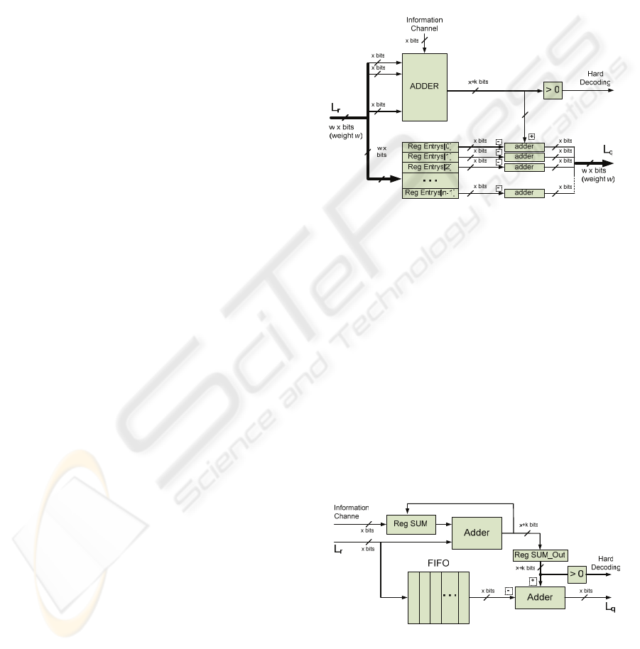
and done in serial or parallel mode.
In a parallel version the inputs are added all
together, producing the value of the a posteriori
pseudo-probability,
n
LQ . The message outputs can
then be computed simultaneously by just subtracting all
entries from the output of the referred adder. This type
of implementation requires an adder capable of adding
1w
+
inputs of x bits, as well as, w output x bits adders
in order to be able to perform the
w subtractions. This
means that a high number of gates is required to
implement just a single processing unit, but has the
great advantage of a minimum delay system (high
throughput), allowing us to lower the clock frequency
which implies a reduction in the power consumption.
...
...
Figure 1: High level HDL model for a BN processor unit -
parallel configuration.
Alternatively, in a serial version, the inputs are
added on a recursive manner as shown in figure 2. The
Reg_Sum register is initialized with the received
channel information. The output messages can be
obtained in a parallel manner as in figure 1, or using a
full serial approach as shown in figure 2, with a new
message being obtained at each clock cycle.
This implementation minimizes the hardware
complexity (measured in terms of number of logic
gates) at the cost of a significant increase in processing
time (time restrictions could require an increase in the
clock frequency). The serial implementation has also
the advantage of supporting the processing of a BN of
any weight, at the expense of little additional control.
Reg Entrys[0]
Reg Entrys[w-1]
Reg Entrys[1]
Reg Entrys[2]
Figure 2: High level HDL model for a BN processor unit -
serial configuration.
SIGMAP 2006 - INTERNATIONAL CONFERENCE ON SIGNAL PROCESSING AND MULTIMEDIA
APPLICATIONS
20
4.2 CN Processing Unit
A similar approach to the one used in the previous
section, can be followed in the computation of the
mn
Lr
messages, sent by a CN. In fact, the boxplus operation
defined in (5) can be reversed as:
x
yz xz y = ⇔ = ¢¯, (10)
where the boxminus operation is defined as:
(
)
2
LUT ,ab ab b −¯ ,
and
()
()()
2
LUT , log 1 log 1
ab ab
ab e e
+−
= −− −.
Also, Equation (5) can be rewritten in the following
way
()
'
'
mn n m nm
nNm
Lr Lq Lq
∈
⎛⎞
=
⎜⎟
⎜⎟
⎝⎠
¯
¢
. (11)
However,
()
1
LUT and
()
2
LUT functions contain
logarithmic operators whose hardware implementation
consumes a significant number of resources. Their
implementation can be significantly simplified by
approximating them by fixed point piece-wise linear
functions, namely, with powers of two based
multiplying factors (shifts and adders) (Hu et al. 2001;
Masera et al. 2005).
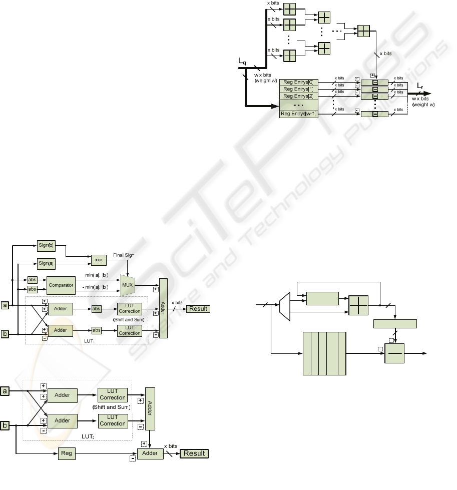
Boxplus and boxminus operations can both be
implemented at the cost of four additions, one
comparison and two corrections, each involving a shift
and a constant addition, as shown in figure 3 and figure
4.
Figure 3: Block diagram of the Boxplus unit.
Figure 4: Block diagram of the Boxminus unit.
Sometimes the boxplus operation is even more
simplified, with a small decrease in performance, by
considering a void correction factor. This simplification
of the SPA algorithm is known by Min-Sum (Chen &
Fossorier 2002; Hu et al. 2001).
Based on the proposed boxplus and boxminus
hardware modules, it is possible to adopt a serial or
parallel configuration for the CN processor (similar to
the ones described for the BN processor unit).
Nevertheless, the complexity of the boxplus operation
on a parallel implementation requires a boxplus-sum
chain of all inputs according to figure 5.
Figure 5: High level HDL model for a CN processor unit -
parallel configuration.
The advantages of one configuration compared with
the other are similar to the ones that were mentioned
for the BN processor. However, it should be noted that
the proportion of silicon area, occupied by a parallel
implementation with respect to a serial implementation,
is in this case significantly higher than the one for the
BN processor, due to the number of operations
involved in the boxplus and boxminus processing. In
fact, the number of gates required by the boxplus and
boxminus processing units is superior to the common
add and subtract arithmetic operations.
Reg SUM
FIFO
Reg Entrys[0]
Reg Entrys[n-1]
Reg Entrys[1]
Reg Entrys[2]
...
+
-
Reg SUM_Out
x bits
x bits
L
r
L
q
x bits
Figure 6: High level HDL model for a CN processor unit -
serial configuration.
5 PROCESSING UNIT FOR A
DVB-S2 LDPC DECODER
The particular characteristics of LDPC-IRA codes
adopted by the DVB-S2 standard turn possible to think
in more efficient decoder solutions that surpass the
HDL LIBRARY OF PROCESSING UNITS FOR GENERIC AND DVB-S2 LDPC DECODING
21
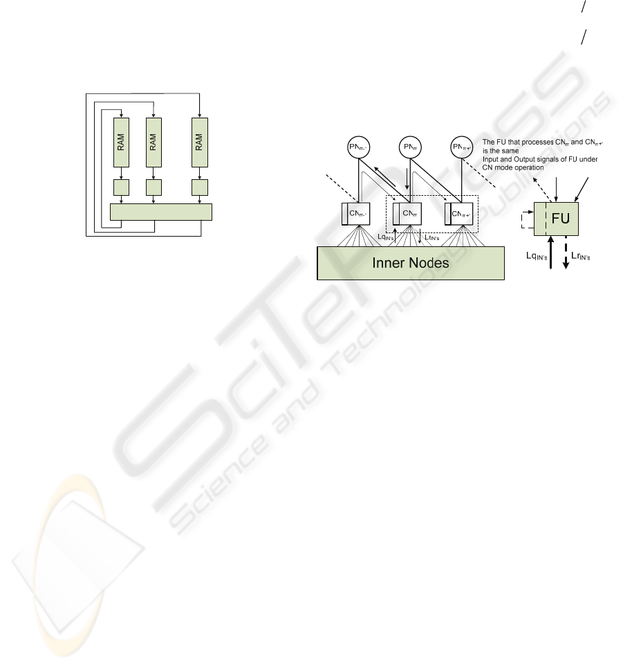
evident limitations of a full parallel architecture. In
figure 7 is presented the basic architecture of a partial
parallel array processor decoder solution for LDPC
DVB-S2 (Kienle et al. 2005). This efficient architecture
not only explores the periodicities of the adopted
LDPC-IRA codes, but also has the great advantage of
supporting all code rates and code lengths defined by
the DVB-S2 standard, through a simple reconfigurable
mechanism.
In this section we suggest a possible
implementation for each processor or functional
processing unit (FU) that merges both the functions
performed by the BN and CN units
Shuffling Network
FU FU FU
...
...
Figure 7: Array processor architecture for a DVB-S2
LDPC decoder.
Since the IN’s are divided in groups of 360
consecutives ones, with the properties of all the IN’s of
a group (i.e. their weight and the indices of the CN’s to
which each one connects) being characterized in terms
of just the 1
st
IN of that group, it turns possible the
simultaneous processing of each IN’s set, which
appreciably simplifies the decoder control. At the other
hand, considering the fact that there are BN’s and CN’s
with different weights, in order to have a processing
unit shared by different BN’s and CN’s, the serial
implementation shown in figures 2 and 6 must be
adopted. Thus, all messages are serially loaded to the
functional units, with the control being based on the
BN’s and CN’s weights.
Attending to the fact that messages sent from CN’s
to BN’s are computed based on the previous messages
received from BN’s, and vice-versa, it means that a
message value once used can be discarded, and the
memory place that it occupies be re-used to store the
new computed message. The shuffling network is
responsible for the correct exchange of the messages
between the CN’s and BN’s emulating the Tanner
Graph.
Considering the zigzag connectivity between PN’s
and CN’s, the PN’s and IN’s are updated following
different schedule methods. The traditional flooding
schedule is carried on the IN’s, while PN’s are updated
jointly with CN’s following the horizontal schedule
approach. This fact requires some modifications on the
CN processing unit from figure 6 in order to construct
the basic functional unit.
As referred, a single FU unit is shared by a constant
number of IN’s, CN’s and PN’s (CN’s and PN’s are
processed jointly), depending on the code length and
rate. More precisely, for a
(
)
,nk
DVB-S2 LDPC-IRA
code, the FU
i
, with 0, , 359i
=
, in BN mode updates
in a serial manner the following IN’s:
(
)
{
}
, 360, 2 360, , 1 360ii i i
α
+ + × + − × , with 360k
α
= .
In CN mode, the same FU updates the CN’s and PN’s:
{
}
,1,, 1jj j q
+ + − , with jiq
=
× and
()
360qnk=− .
The used 360 FU’s operate in parallel and share all the
control signals. They are sufficient to process in real
time all the
n BN’s and nk
−
CN’s of the code.
In BN mode, only IN’s are processed and the FU
layout is similar to figure 2.
MEM
1m
PN
L
q
−
m
P
N
L
q
MEM
MEM
MEM
Lq
PNm
L
r
P
N
m
-
1
m
P
N
L
p
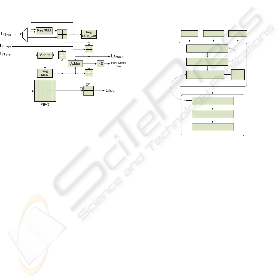
Figure 8: FU in CN mode and zigzag connectivity
between PN’s and CN’s.
In CN mode, each FU updates not only the
associated CN’s but also the corresponding PN’s (note
that per each CN restriction exists a PN bit). Attending
to the zigzag connectivity between PN’s and CN’s,
when updating a PN, say
m , according to (6), it works
as a simple passing node because the message that it
sends to the CN
m+1
is simply the message received
from CN
m
added to the channel information, and vice-
versa (see figure 8). Since each FU processes
q
consecutive CN’s, the PN’s updating can follow a
horizontal schedule approach (both PN’s and CN’s
processed simultaneously). This way, the message that
travels through CN
m , PN m and CN 1m + is kept in
the FU and only the backward message that is sent
from CN
m to PN 1m
−
,
1m
mPN
Lr
−
→
, is saved in the
external memory. The equations that describe the
operation of the FU in CN mode are:
()
'
'\
m
mn n m PN m
nINmn
Lr Lq Lq Mem
→
∈
⎛⎞
=
⎜⎟
⎜⎟
⎝⎠
¢¢
¢
(12)
()
1
'
'
mm
mPN nm PN m
nINm
Lr Lq Lq
−
→→
∈
⎛⎞
=
⎜⎟
⎜⎟
⎝⎠
¢
¢
(13)
11mm
PN m PN
LQ Mem Lr
−
−
→
=+ (14)
()
'
'
m
nm PN
nINm
M
em Lq Mem Lp
∈
⎡⎤
⎛⎞
=⎢ ⎥+
⎜⎟
⎜⎟
⎢⎥
⎝⎠
⎣⎦
¢
¢
(15)
SIGMAP 2006 - INTERNATIONAL CONFERENCE ON SIGNAL PROCESSING AND MULTIMEDIA
APPLICATIONS
22
where
()
I
Nm means the set of IN connected to CN m ,
and Mem the internal memory of the FU.
A problem arises when CN’s
m and 1m + are not
processed by the same FU. This situation occurs
cyclically whenever
(1)mod 0mq+=, which means that
if CN
m is processed by the FU
i
, then, CN 1m
+
will
be processed by the FU
i+1
. This situation was solved by
transferring the contents of memory FU
i
to FU
i+1
, with
0, , 358i = , and FU
0
initialized with the ¢ neutral
element (maximum admissible LLR value). This
significantly simplifies the system control.
Figure 9 presents the architecture of a FU in CN
mode.
Reg Entrys[0]
Reg Entrys[n-1]
Reg Entrys[1]
Reg Entrys[2]
Figure 9: High level HDL model for the FU architecture in
CN mode.
The FU system control guaranties that equations
(12) to (15) are computed according to that order.
6 AUTOMATIC HDL CODE
GENERATION WITH A
MATLAB PRE-PROCESSOR
As mentioned, a LDPC is a linear code described by a
sparse parity check matrix. Also, LDPC codes with
good error correcting capabilities have normally long
codeword widths (> 10000 bits per codeword) which
means that the hand design of the Verilog/VHDL
decoder may seem almost impossible. Besides that,
minor changes on the H matrix always have
considerable repercussions on the structure of the
correspondent LDPC decoder, even when the
architecture principles remain unchanged. Those
simple modifications may represent a considerable
amount of time in the development of the
Verilog/VHDL code of the decoder.
Considering the fact that LDPC decoders can be
constructed taking a modular approach and the basic
LDPC decoding operations, such as boxplus and
boxminus, are hardware translated by independent
modules that can be assembled accordingly to the
decoder architecture, it allows the usage of auxiliary
tools/libraries in their development.
Following these considerations, it is possible to
design Matlab
©
libraries containing the basic building
LDPC decoder blocks. Those simple blocks (for ex.
BN processing unit – parallel configuration), are fully
configurable (number of inputs, message precision,
etc.). The design of a LDPC decoder for a particular
code according to a previously defined architecture is,
thus, achieved. A simple Matlab
©
application script
receives the parity check matrix of the code, interprets
it and, accordingly, creates and connects a full set of
module units needed to implement the required
decoder. The procedure is described in figure 10.
Algorithm Tests
Algorithm Implementation
HDL Module Generation
MATLAB
Synthesis
Simulation
FPGA Implementation
HDL
HDL
Library
H matrix
Architecture
Type
Resolution
Figure 10: Automatic HDL decoder design flowchart.
7 CONCLUSIONS
In this paper we have proposed an efficient and generic
HDL library of processing units which combined with
Matlab
©
scripting for automatic HDL code generation,
allows a flexible approach to the construction of
generic and DVB-S2 LDPC decoders. This technique
considerably reduces the design development time,
especially for long codes such as the ones adopted to
the DVB-S2 standard.
REFERENCES
Chen, J. & Fossorier, M., 2002, ‘Near Optimum Universal
Belief Propagation Based Decoding of Low-Density
Parity Check Codes’, IEEE Transactions on
Communications, vol. 50, no. 3, pp. 406 - 414.
Eroz, M., Sun, F. & Lee, L., 2004, ‘DVBS2 low density
parity check codes with near Shannon limit
performance’, International Journal of Satellite
HDL LIBRARY OF PROCESSING UNITS FOR GENERIC AND DVB-S2 LDPC DECODING
23

Communications and Networking, vol. 22, no. 3, pp.
269-279.
ETSI, 2005, Digital Video Broadcasting (DVB) Second
generation framing structure for broadband satellite
applications, EN 302 307 V1.1.1.
Gallager, R., 1962, ‘Low-Density Parity-Check Codes’,
IRE Transactions on Information Theory, vol. IT-8,
pp.21-28.
Hu, X., Eleftheriou, E., Arnold, D. & Dholakia, A., 2001,
‘Efficient Implementations of the Sum-Product
Algorithm for Decoding LDPC Codes’, IEEE
GLOBECOM '01, vol. 2, pp. 1036 - 1036E.
Kienle, F., Brack, T. & Wehn, N., 2005, ‘A Synthesizable
IP Core for DVB-S2 LDPC Code Decoding’,
DATE’05, vol. 3, pp. 100-105.
Kschischang, F., Frey, B. & Loeliger, H., 2001, ‘Factor
Graphs and the Sum-Product Algorithm’, IEEE
Transactions on Information Theory, vol. 47, no. 2,
pp. 498-519.
MacKay, D. & Neal, R., 1996, ‘Near Shannon Limit
Performance of Low Density Parity Check Codes’,
IEEE Electronics Letters, vol. 32, no.18, pp.
1645-1646.
Masera, G., Quaglio, F. & Vacca, F., 2005, ‘Finite
precision implementation of LDPC decoders’, IEE
Proceedings-Communications, vol. 152, No. 6, pp.
1098-1102.
Sharon, E., Litsyn, S. & Goldberger, J., 2004, ‘An
efficient message-passing schedule for LDPC
decoding’, 23rd IEEE Convention of Electrical and
Electronics Engineers in Israel Proceedings, pp.
223-226.
Tanner, R., 1981, ‘A Recursive Approach to Low
Complexity Codes’, IEEE Trans. Inform. Theory, vol.
27, pp. 533-547.
Xiao, H. & Banihashemi, A., 2004, ‘Graph-Based
Message-Passing Schedules for Decoding LDPC
Codes’, IEEE Transactions on Communications, vol.
52, no. 12, pp. 2098-2105.
Zhang, J. & Fossorier, M., 2002, ‘Shuffled Belief
Propagation Decoding’, Signals, Systems and
Computers 2002. Conference Record of the Thirty-
Sixth Asilomar Conference on, vol.1, pp. 8-15.
SIGMAP 2006 - INTERNATIONAL CONFERENCE ON SIGNAL PROCESSING AND MULTIMEDIA
APPLICATIONS
24
