A TEMPORAL SYNCHRONIZATION MECHANISM FOR
REAL-TIME DISTRIBUTED CONTINUOUS MEDIA
Luis A. Morales Rosales, Saul E. Pomares Hernandez
Computer Science Department,
National Institute of Astrophysics, Optics and Electronics (INAOE)
Luis Enrique Erro No. 1, 72840 Tonantzintla, Puebla, Mexico.
Keywords:
Continuous media, distributed systems, synchronization media, and causal ordering.
Abstract:
The preservation of temporal relations for real-time distributed continuos media is a key issue for emerging
multimedia applications, such as Tele-Immersion and Tele-Engineering. Although several works try to model
and execute distributed continuous media scenarios, they are far from resolving the problem. The present paper
proposes a viable solution based on the identification of logical dependencies. Our solution considers two
main components. First, it establishes a temporal synchronization model that expresses all possible temporal
scenarios for continuous media according to their causal dependency constraints. The second component
consists of an innovative synchronization mechanism that accomplishes the reproduction of continuous media
according to its temporal specification. We note that the present work does not require previous knowledge of
when nor for how long the continuous media of a temporal scenario is executed.
1 INTRODUCTION
The subject of synchronization for distributed con-
tinuous media addresses the problem of preserving
temporal relations among streams (continuous media)
having geographically distributed sources. The syn-
chronization in this kind of media is carried out with-
out previous knowledge of when or for how long the
streams are or will be executed. Several works at-
tempt to resolve this problem. We can group them ac-
cording to their synchronization model into two broad
categories: synchronous and asynchronous. The main
difference between these categories relates to whether
they consider in some way or not a common reference
(virtual or physical clocks, shared memory, off-line
synchronization, etc). While a common reference is
present in the synchronous category, it is absent in
the asynchronous one. Most works fall into the syn-
chronous category (Allen, 1983; Pantelis et. al, 2000;
Colin, 1998). These works usually try to answer the
synchronization problem by measuring the period of
physical or virtual time elapsed (△
t
) between certain
points in a timeline. Such points can be the begin
(x
−
) and/or end (x
+
) events of the continuous me-
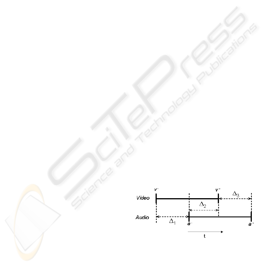
dia involved (See Fig. 1). Only few works deal with
the problem in an asynchronous manner (Grigoras et.
al, 2003; Grigoras et. al, 2005; Yutaka et. al, 1999;
Chang et. al, 2003; Kshemkalyani, 1996). They pri-
marily take into account logical dependencies instead
of temporal dependencies. One representative work is
the model introduced in (Grigoras et. al, 2003; Grig-
oras et. al, 2005), which determines the possible re-
lations of continuous media by identifying causal de-
pendencies between the begin and end events. For ex-
ample, in Fig. 1, Grigoras et al. establish the overlaps
relation as (v
−
→ a
−
∧ a
−
→ v
+
∧ v
+
→ a
+
).
Figure 1: Example of a temporal scenario.
Neither approach taken by the works in the two
general categories fulfills the requirements needed to
solve the issue of preserving temporal relationships.
This can be explained by several reasons. First, it is
not easy to have a common reference in distributed
systems since these involve the lack of a global
302
A. Morales Rosales L. and E. Pomares Hernandez S. (2006).
A TEMPORAL SYNCHRONIZATION MECHANISM FOR REAL-TIME DISTRIBUTED CONTINUOUS MEDIA.
In Proceedings of the International Conference on Signal Processing and Multimedia Applications, pages 302-309
DOI: 10.5220/0001572403020309
Copyright
c
SciTePress

time clock and shared memory. Second, solely
considering logical dependencies among begin and
end events may result in inaccurate executions. For
example, a synchronization mechanism can ensure
that the reproduction of events fulfills v
−
→ a
−
,
but the model does not specify how much time must
elapse between the reproduction of v
−
and a
−
.
In this paper we propose a solution belonging
to the asynchronous category that attempts to resolve
the problem related to possible imprecisions. To
achieve this, we work with the continuous media at
two abstract levels. At the higher level, the temporal
duration is taken into account by representing the
continuous media segments as intervals. At the lower
level, we work with intervals, considering that an
interval is composed of a set of sequentially-ordered
messages. Taking into consideration these two
abstract levels, our synchronization model translates
temporal scenarios to be expressed as subintervals
(segments) arranged according to their logical prece-
dence dependencies. This translation results in the
creation of what we call logical mappings.
The structure of this paper is as follows. We
present in Section 2 the system model, the back-
ground and some required definitions. The Temporal
Synchronization Model is presented in detail in Sec-
tion 3. We introduce in Section 4 our Synchronization
Mechanism. Finally, conclusions are provided in
Section 5.
2 PRELIMINARIES
2.1 The System Model
Processes: The application under consideration
is composed of a set of processes P = {i, j...},
organized into a group that communicates by reliable
broadcast asynchronous messages. A process can
only send one message at a time.
Messages: We consider a finite set of messages
M, where each message m ∈ M is identified by a
tuple m = (p, x), where p ∈ P is the sender of m,
denoted by Src(m), and x is the local logical clock
for messages of p when m is broadcasted. The set of
destinations of a message m is always P .
Events: Let m be a message. We denote by
send(m) the emission event of m by Src(m), and by
delivery(p, m) the delivery event of m to participant
p ∈ P . The set of events associated to M is then the
set E = {send(m) : m ∈ M } ∪ {delivery(p, m) :
m ∈ M ∧ p ∈ P }. The process p(e) of an event
e ∈ E is defined by p(send(m)) = Src(m) and
p(delivery(p, m)) = p. The set of events of a
process p is E
p
= {e ∈ E : p(e) = p}.
Intervals: We consider a finite set I of inter-
vals, where each interval A ∈ I is a set of messages
A ⊆ M sent by a participant p = P art(A), defined
by the mapping P art : I → P . Formally, we
have m ∈ A ⇒ Src(m) = P art(A). Due to
the sequential order of P art(A), we have for all
m, m
′
∈ A, m → m
′
or m
′
→ m. We denote by a
−
and a
+
the endpoint messages of A, such that for all
m ∈ A : a
−
6= m and a
+
6= m ⇒ a
−
→ m → a
+
.
2.2 Background and Definitions
2.2.1 The Happened-Before Relation for Single
Events
The happened-before relation, also known as the
causal relation, was introduced in (Lamport, 1978).
It is a strict partial order (i.e. irreflexive, asymmetric,
and transitive) defined as follows:
Definition 1. The causal precedence relation, de-
noted by “→”, is the partial order generated by the
following pair:
1. e → e
′
for all e, e
′
such that p(e) = p(e
′
) and e
occurs before e
′
on p(e)
2. send(m) → delivery(k, m) for every message m
and process k
We note that the complement to the causal prece-
dence is the concurrent relation defined as e k e
′
⇒
¬(e → e
′
∨ e
′
→ e). The precedence relation
on messages denoted by m → m
′
is induced by
the precedence relation on events, and is defined by
m → m
′
⇒ send(m) → send(m
′
).
A behavior or a set of behaviors satisfies causal or-
der delivery if the diffusion of a message m causally
precedes the diffusion of a message m
′
, and the deliv-
ery of m causally precedes the delivery of m
′
for all
participants that belong to P . Formally, we have:
Definition 2. Causal Order Delivery (broadcast
case): If send(m) → send(m
′
), then ∀p ∈ P :
delivery(p, m) → delivery(p, m
′
)
2.2.2 The Partial Causal Relation
The Partial Causal Relation (PCR) was introduced in
(Fanchon et. al, 2004) (Definition 3). It considers a
subset M
′
⊆ M of messages. The PCR induced by
M
′
considers the subset of events E
′
⊆ E that denote
E
′
= {send(m), m ∈ M
′
} ∪ {delivery(p, m), m ∈
M
′
, p ∈ P }. For any identifier p ∈ P , we have
E
′
p
= E
′
∩E
p
. The partial precedence →
M
′
⊆ E
′
×E
′
induced by M
′
is the least partial order relation (tran-
sitive and acyclic) on E
′
and it is defined as follows:
A TEMPORAL SYNCHRONIZATION MECHANISM FOR REAL-TIME DISTRIBUTED CONTINUOUS MEDIA
303

Definition 3. The partial causal relation “→
M
′
” is
the least partial order relation satisfying the two fol-
lowing properties:
1. For each participant p ∈ P , the local restrictions of
→
M
′
and → to the events of E
′
p
coincide: ∀e, e
′
∈
E
′
p
: e → e
′
⇔ e →
M
′
e
′
.
2. For each message m ∈ M
′
and p ∈ P ,
the emission of m precedes its delivery to p:
send(m) →
M
′
delivery(p, m).
2.2.3 Happened-Before Relation for Intervals
In (Lamport, 1986) it was established that an inter-
val A precedes or happens before another interval B
if all elements that compose interval A causally pre-
cede all elements of interval B. This definition is used
in the model presented in Section 3. However, it is
well known that causal ordering implicates a com-
putational high cost in terms of overhead, delay and
processing time. For this reason, in order to reduce
the cost, our mechanism presented in Section 4 uses
the definition of the happened-before relation for in-
tervals that was proposed in (Morales, 2005) (Defini-
tion 4) which is expressed only in terms of the inter-
val endpoints. This definition says that if the elements
of an interval are sequentially ordered, then ensuring
partial causal order (Definition 3) on the interval end-
points is sufficient to ensure causal ordering at an in-
terval level.
Definition 4. The relation “→
I
” on the set of in-
tervals I of a system is accomplished if it satisfies the
following two conditions:
1. A →
I
B if a
+
→
M
′
b
−
2. A →
I
B if ∃C|(a
+
→
M
′
c
−
∧ c
+
→
M
′
b
−
)
where a
+
and b
−
are the right and left endpoints
(messages) of A and B, respectively, c
−
and c
+
are
the endpoints of C, and →
M
′
is the partial causal or-
der (Definition 3) induced on M
′
⊆ M where M
′
, is
the subset composed by the endpoint messages of the
intervals in I. The second condition is the transitive
property. Now, we present the simultaneous relation
for intervals as follows:
Definition 5. Two intervals, A and B, are said to
be simultaneous “|||” if the following condition is sat-
isfied:
A|||B ⇒ a
−
k b
−
∧ a
+
k b
+
Finally, we present the definition of causal delivery
for intervals based on their endpoints as follows:
Definition 6. Causal Broadcast Delivery for Inter-
vals
If (a
+
, b
−
) ∈ A×B, send(a
+
) →
M
′
send(b
−
) ⇒
∀p ∈ P, delivery(p, a
+
) →
M
′
delivery(p, b
−
), then
∀p ∈ P, delivery(p, A) →
I
delivery(p, B)
2.3 Temporal Synchronization
Model
In order to achieve the synchronization between con-
tinuous media in distributed systems, we propose to
determine temporal relations based on the identifica-
tion of logical precedence dependencies. To achieve
this, we translate temporal scenarios to be expressed
in terms of the precedence relation and the simulta-
neous relation; we call these translations logical map-
pings. More explicitly, in our work, a logical mapping
decomposes a temporal scenario into data segments
(events) that are arranged according to their possible
precedence dependencies.
2.4 Logical Mappings
The process to create logical mappings (Table 1) in-
volves taking every pair of intervals in the system that
compose a temporal scenario, and translating each
pair into four data segments, which are determined
according to the possible precedence dependency of
the discrete events that compose them. These data
segments, according to our definition, become new
intervals. The resulting intervals are only expressed
in terms of the happened-before relation and the si-
multaneous relation
1
.
Table 1: Logical Mapping.
∀(X, Y ) ∈ I × I
A(X, Y ) ← • {x ∈ X : x → y
−
}
if x
−
→ y
−
or
• ⊘ otherwise
B(X, Y ) ← • {y ∈ Y : x
+
→ y}
if x
+
→ y
+
or
• {x ∈ X : y
+
→ x}
if y
+
→ x
+
or
• ⊘ otherwise
C(X, Y ) ← X − (A(X, Y ) ∪ B(X, Y ))
D(X, Y ) ← Y − B(X, Y )
W (X, Y ) ← C|||D
S(X, Y ) ← A →
I
W →
I
B
In order to consider the seven basic relations and
their inverses, and to maintain the model simplified,
we first identify the X and Y intervals for each pair
of intervals in the system. The X interval will be the
interval with the first left endpoint, and the Y interval
will be the remaining interval. This is done to ensure
1
We consider in our work that an interval can be empty.
In such case, the following properties apply:
• ⊘ →
I
A ∨ A →
I
⊘ = A
• ⊘|||A ∨ A|||⊘ = A
SIGMAP 2006 - INTERNATIONAL CONFERENCE ON SIGNAL PROCESSING AND MULTIMEDIA
APPLICATIONS
304

Figure 2: X overlapsY relation and its logical mapping
A →
I
(C|||D) →
I
B.
that for every pair, x
−
→ y
−
or x
−
||y
−
at all times.
Once the X and Y intervals are identified, the model
segments each pair into four subintervals, A, B, C
and D (see Table 1). We now proceed to construct
the general causal structure S = A →
I
W →
I
B,
where W determines if overlaps exist between the
present pair. For example, for the overlaps relation
defined in (Allen, 1983), the logical mapping is equal
to A →
I
(C|||D) →
I
B (See Fig. 2). Our model
defines five possible logical mappings (Table 2, right
column), which we call: precedes, overlaps, ends,
starts, and simultaneous. These five logical mappings
are sufficient to represent the thirteen relations estab-
lished in (Allen, 1983). As shown in Table 2, we are
now able to express every possible temporal relation
by only considering the interval happened-before re-
lation and the interval simultaneous relation.
2.5 Synchronization Mechanism
Our synchronization mechanism carries out two
main functions that allow the continuous media to be
presented according to the temporal model previously
presented. The first function makes the translation of
temporal relations (logical mappings), and the second
function ensures the presentation of the intervals
(data segments) according to the resultant logical
mapping.
In order to carry out the temporal synchroniza-
tion, our mechanism, which is based on the resultant
logical mapping, determines if an interval must begin
to be delivered or not according to whether it satisfies
or not its causal dependency. For example, in Figure
2, interval A precedes interval D. Therefore, interval
D will not begin to be delivered until all messages
of A have been delivered. When the intervals are
simultaneous in this case, C and D, the messages of
C can be delivered in any order with respect to the
messages of D.
General description. Internally, the mecha-
nism uses two kinds of ordered messages: causal
messages and FIFO messages. We have three differ-
ent causal messages: begin, end, and cut. The begin
and end messages are the left and right endpoints of
the original intervals, and cut is a control message
used by the mechanism to inform about an interval
segmentation. FIFO messages (fifo
p) are used
only inside an interval. We note that all causal and
FIFO messages carry data of the continuous media
involved. In order to ensure the causal order delivery
at an interval level according to Definition 6, our
algorithm uses vector clocks (Fidge, 1989) and the
immediate dependency relation (IDR) (Pomares et.
al, 2004). We use the IDR relation to determine the
sufficient causal control information that must be
attached per message. Next, we describe the main
components of the mechanism.
2.6 Data Structures
Local states. The state of a process p is de-
fined by three data structures: V T (p), CI(p) and
last
fifo(p).
• V T (p) is the vector time. For each process p there
is an element V T (p)[j] where j is a process identi-
fier. A process can only send one message at a time.
The size of V T is equal to the number of processes
in the group. The element V T (p)[j] represents the
greatest number of messages of the identifier j and
“seen” in causal order by p. It is through the V T (p)
structure that we are able to guarantee the causal
delivery at an interval level.
• CI(p) is the control information structure. It is
a set of entries c
k,t
= (k, t) where (k, t) is a mes-
sage identifier (the message diffused by the process
identifier k with the local message clock value t).
Structure CI(p) also contains information about
the causal history of p.
• last
fifo(p) is the fifo control information
structure. It is a structure composed by a set of
entries (k, t), where (k, t) is a message identifier.
The last
fifo structure has information about
the last (f if o
p) messages received by p. These
(fifo
p) messages represent potential causal
messages.
Messages. The mechanism uses causal messages
(begin, end, cut) and FIFO messages (f if o p). A
message m, in general, is composed of an iden-
tifier (k, t), an attached causal information H(m),
and continuous media data in the structure called
data. For f if o p messages, structure H(m) is al-
ways H(m) = ⊘. Formally, a message m is a tuple
m = (k, t, T P, H(m), data), where:
• k is the identifier of sender k = Src(m).
• t = V T (p)[k] is the (local) clock value of p for the
identifier k when a causal message m (begin, end,
A TEMPORAL SYNCHRONIZATION MECHANISM FOR REAL-TIME DISTRIBUTED CONTINUOUS MEDIA
305
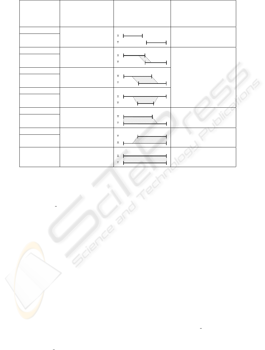
Table 2: Allen’s relations and their corresponding logical mappings.
Allen’s
Relations
Endpoints
Interval Temporal
Relation
Logical Mappings
Xbefore Y x
+
→ y
−
Precedes:
Y after X A →
I
B
Xmeets Y x
+
||y
−
Y meet-by X
Xoverlaps Y x
−
→ y
−
→ x
+
∧ Overlaps:
Y overlap-by X x
+
→ y
+
A →
I
(C|||D) →
I
B
Xincludes Y x
−
→ y
−
∧
Y during X y
+
→ x
+
Xstarts Y x
−
k y
−
∧ Starts:
Y started-by X x
+
→ y
+
(C|||D) →
I
B
Xfinishes Y x
+
k y
+
∧ Ends:
Y finished-by X x
−
→ y
−
A →
I
(C|||D)
Xequals Y x
−
k y
−
∧ Simultaneous:
x
+
k y
+
C|||D
or cut) is sent. The value of t indicates the sequen-
tial number to which causal message m belongs.
• T P is the type of message
(begin, end, cut, fifo
p).
• H(m) contains identifiers of messages (k, t)
causally preceding causal message m, which de-
notes the begin and/or end of other intervals. The
information in H(m) ensures the causal delivery
of message m. Structure H(m) is built before a
causal message is broadcasted, and then it is at-
tached to the causal message.
• data is the structure that carries the media data.
2.7 Example Scenario
Construction of logical mappings. We explain the
creation of logical mappings in the example of the
overlaps relation shown in Fig. 3. The referenced
lines correspond to the code shown in the Table 3.
In this example, segment A must first be determined.
To achieve this, we map the left causal boundary
a
−
with the begin send event send( x
−
= x
1
),
and the right causal boundary with the send event
send(a
+
= x
k
). The right endpoint a
+
is deter-
mined by the last (fifo
p) message received by par-
ticipant j before the begin send event send(y
−
) (lines
16-20). Once we know the causal boundaries of A,
we determine the set of messages that compose it
(A = {x
1
, x
2
, ..., x
k
}). After interval A is identified,
we proceed to determine the causal boundaries of C
and D. At this point, we can identify the left causal
boundaries c
−
= x
k+1
and d
−
= y
1
. However, it
is only until the end send event of endpoint x
+
and
its corresponding delivery event that we can identify
the right endpoints of C and D. With the end send
event send(x
+
= x
n
) we establish that c
+
= x
n
,
and consequently, C = {x
k+1
, x
k+2
, ..., x
n
}. At
the reception of x
+
by participant j, our algorithm
sends a cut message (lines 49-51) which establishes
the end of interval D(d
+
= y
l
) and the beginning
of interval B(cut = b
−
= y
l+1
). As a result, we
have D = {y
1
, y
2
, ..., y
l
}. Finally, with the send
event of y
+
, we have b
+
= y
m
, and consequently,
B = {y
l+1
, y
l+2
, ..., y
m
}.
In general, our mechanism considers three impor-
tant rules to create logical mappings:
1. When x
−
→ y
−
: the right endpoint a
+
is deter-
mined by the last (f ifo
p) message received by
participant j before the send event of y
−
, where
j = P art(Y ).
2. When x
+
→ y
+
: at the reception of x
+
by par-
ticipant j, we generate on j a cut message (only if
SIGMAP 2006 - INTERNATIONAL CONFERENCE ON SIGNAL PROCESSING AND MULTIMEDIA
APPLICATIONS
306

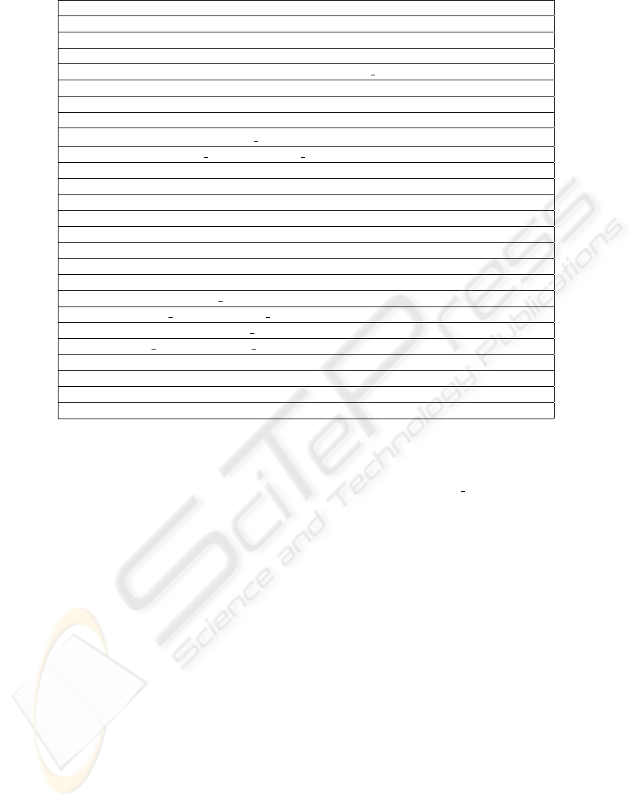
Table 3: Specification of the synchronization mechanism.
Initially
1. V T (p)[j] = 0, ∀j : 1, ..., n
2. CI(p) ← ⊘
3. last f if o(p) ← ⊘
4. Act = 0
For each message m diffused by p with the process identifier i
5. send(Input : T P = {begin|end|cut|fifo p})
6. V T (p)[i] = V T (p)[i] + 1
7. If not (T P = f ifo p) then
8. If not (T P = begin) then /*Construction of the H(m)for end and cut messages*/
9. H(m) ← CI(p)
10. if (T P = end) then
11. Act = 0 /*Indicates that process p is inactive*/
12. endif
13. else /*Construction of the H(m) for begin messages*/
14. Act = 1 /*Indicates that process p is sending an interval*/
15. ∀(s, r) ∈ CI(p)
16. if ∃(x, l) ∈ last f if o(p) | s = x then /*Adding info about f ifo p messages
to CI(p)*/
17. if not ((s, r) = max{(x, l), (s, r)}) then
18. CI(p) ← CI(p) ∪ (x, l)
19. endif
20. endif
21. H(m) ← CI(p)
22. last f if o(p) ← ⊘
23. endif
24. CI ← ⊘ /*Erases the CI(p) on each causal message sent*/
25. else */Construction of the H(m) for f if o p messages*/
26. H(m) ← ⊘
27. endif
28. m = (i, t = V T (p)[i], T P, H(m), data)
29. sending(m)
For each message received by p with process identifier j
30. receive(m) in p with i 6= j and m = (k, t, T P, H(m), data)
31. If t = V T (p)[k] + 1 then /* FIFO delivery condition*/
32. If not (T P = f ifo p) then
/*Causal delivery condition*/
33. If not (t
′
≤ V T (p)[l])∀(l, t
′
) ∈ H(m)) then
34. wait()
35. else /*Causal delivery procedure*/
36. delivery(m)
37. V T (p)[k] = V T (p)[k] + 1
A TEMPORAL SYNCHRONIZATION MECHANISM FOR REAL-TIME DISTRIBUTED CONTINUOUS MEDIA
307
38. If ∃(s, r) ∈ CI(p) | k = s then
39. CI(p) ← CI(p) \ {(s, r)}
40. endif /*Updating CI(p) with a more recent message*/
41. CI(p) ← CI(p) ∪ {(k, t)}
42. ∀(l, t
′
) ∈ H(m) /*Clears CI(p) and last fifo(p) */
43. If ∃(s, r) ∈ CI(p) | l = s and r ≤ t
′
then
44. CI(p) ← CI(p) \ (s, r)
45. endif
46. If ∃(x, l) ∈ last f if o(p) | l = x and l ≤ t
′
then
47. last f if o(p) ← last f if o(p) \ (x, l)
48. endif
49. If Act = 1 and not(T P = cut) and not(T P = begin) then
50. send(cut) /*Sending a cut message*/
51. endif
52. endif
53. else /*FIFO delivery procedure*/
54. delivery(m)
55. V T (p)[k] = V T (p)[k] + 1
56. If ∃(x, l) ∈ last f if o(p) | k = x then
57. last f if o(p) ← last f if o(p) \ (x, l)
58. endif /*Updating last f if o(p) with a more recent message*/
59. last f if o(p) ← last f ifo(p) ∪ (k, t)
60. endif
61. else
62. wait()
63. endif
j is sending an interval), which determines the be-
ginning of interval B (cut = b
−
= y
l+1
) and the
end of interval D(d
+
= y
l
).
3. When y
+
→ x
+
: at the reception of y
+
by
participant i = P art(X), we generate on i a
cut message (only if i is sending an interval),
which determines the beginning of interval B
(cut = b
−
= x
q+1
) and the end of interval
C(c
+
= x
q
).
Carrying out causal order delivery. The re-
sultant logical mapping for the example scenario is
A →
I
(C|||D) →
I
B. To ensure interval causal
delivery in terms of their endpoints (Definition 6) we
need to ensure that:
• delivery(a
+
) →
M
′
delivery(c
−
),
• delivery(a
+
) →
M
′
delivery(d
−
),
• delivery(c
+
) →
M
′
delivery(b
−
) and
• delivery(d
+
) →
M
′
delivery(b
−
)
Since a
+
= x
k
, c
−
= x
k+1
, d
+
= y
l
and b
−
= y
l+1
, the procedure of deliv-
ery(a
+
) →
M
′
delivery(c
−
) and delivery(d
+
)
→
M
′
delivery(b
−
) is accomplished by the FIFO
property implemented by lines 6 and 31. The
procedure of delivery(a
+
) →
M
′
delivery(d
−
) is ac-
complished in the following way. Initially, message
a
+
= x
k
is sent as fifo
p. To consider it as a causal
message, process j includes information concerning
x
k
in its causal history (lines 16-20), and attaches
this information to structure H(m) of the message
d
−
= y
1
before its send event (line 21).
The causal delivery condition (line 33) ensures
that the beginning of interval D (d
−
) will be de-
livered only after the delivery of x
k
, and the FIFO
condition (line 21) ensures that x
k
will be delivered
only after the delivery of all messages x
h
∈ A ⊆ X,
such that h < k . For the requirement of delivery(c
+
)
→
M
′
delivery(b
−
), message b
−
= y
l+1
has attached
information on its structure H(m) about the message
c
+
= x
n
(lines 15-21). The causal delivery condition
(line 33) ensures that the beginning of interval B
(b
−
) will be delivered only after the delivery of x
n
,
and the FIFO condition (line 21) ensures that x
n
will
be delivered only after the delivery of all messages
x
q
∈ C ⊆ X, such that q < n.
SIGMAP 2006 - INTERNATIONAL CONFERENCE ON SIGNAL PROCESSING AND MULTIMEDIA
APPLICATIONS
308
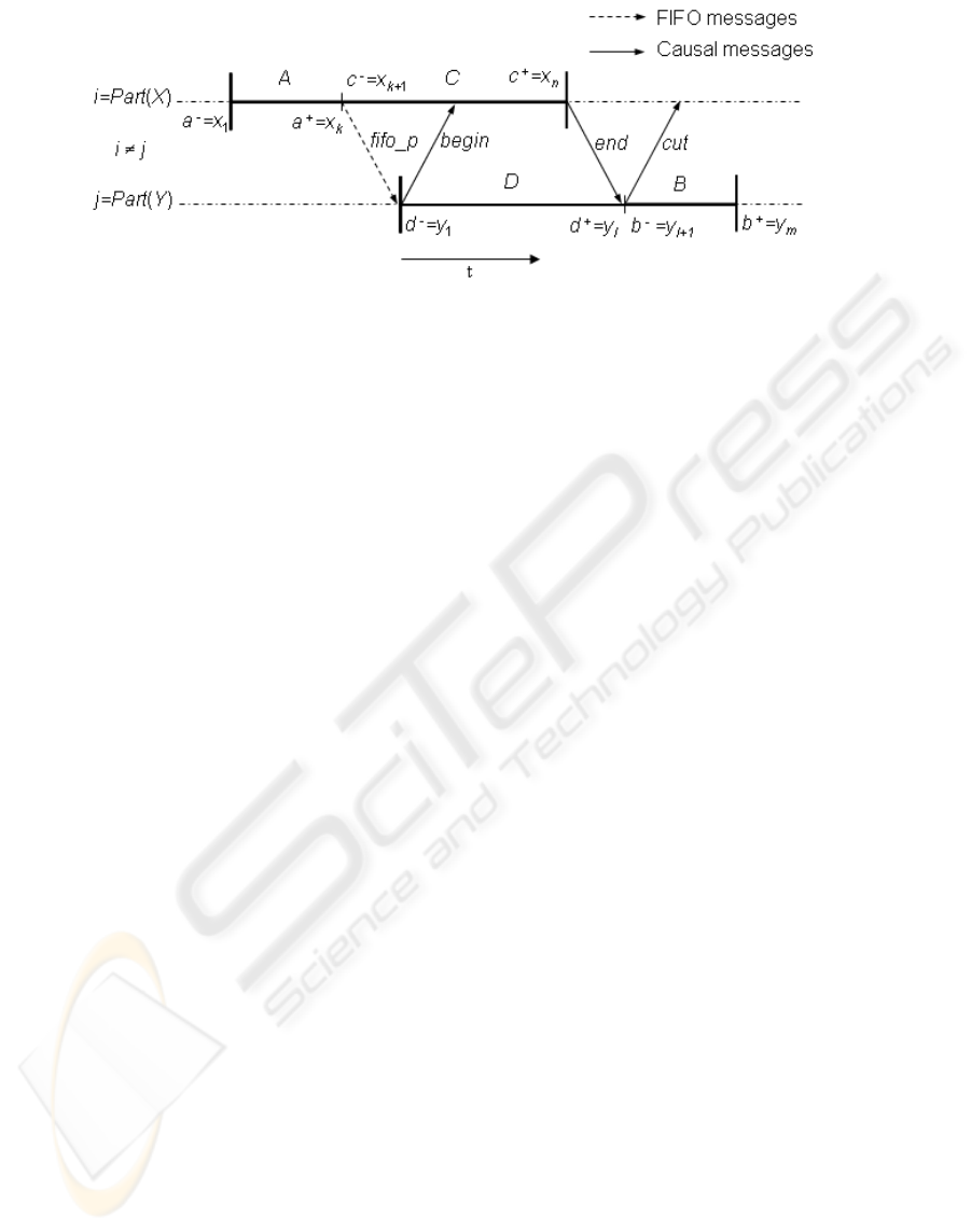
Figure 3: Construction of the logical mapping (A →
I
(C|||D) →
I
B) for the overlaps relation.
3 CONCLUSIONS
An innovative temporal synchronization mechanism
has been presented. The mechanism addresses in
an asynchronous manner the problem of preserv-
ing temporal relations for real-time distributed media
streams. The core of our mechanism is the delivery
of streams according to the resultant logical mapping
which is based on the causal dependencies of the con-
tinuous media involved. The mechanism uses the par-
tial causal relation and the immediate dependency re-
lation to reduce the causal overhead. Further work is
needed to enhance our mechanism so that it can sup-
port real network conditions (loss of messages, life-
time of messages, etc.). Our attention is focused in
this direction, and we expect to publish some interest-
ing contributions shortly.
REFERENCES
James F. Allen. (1983). Maintaining Knowledge about
Temporal Intervals. In Communications of the ACM,
Vol 26, Num 11, 832-843.
Pantelis Balaouras, Ioannis Stavrakakis, Lazaros F. Mer-
akos. (2000). Potential and Limitations of a Teleteach-
ing Environment based on H.323 Audio-Visual. In
Communication Systems. Computer Networks, Vol 34,
Num 6, 945-958.
Colin Perkins. (2003). RTP Audio and Video for Internet.
Addison Wesley, USA, ISBN: 0672322498.
Romulus Grigoras, Philippe Mauran, Girard Padiou,
Philippe Queinnec. (2003). Ordonnancement Causal
de Flux Repartis Multimedias. In Formalisation des
Activites Concurrentes FAC’2003.
Cezar Plesca, Romulus Grigoras, Philippe Queinnec, Girard
Padiou. (2005). Streaming with Causality: A Practical
Approach. In ACM Multimedia 2005, Singapore, 6-
11.
Yutaka Ishibashi, Shuji Tasaka, Yoshiro Tachibana. (1999).
A Media Synchronization Scheme with Causality
Control in Network Environments. In Proceedings
26th Conference on Local Computer Networks, Low-
ell, Massachusetts, USA, IEEE Computer Society,
232-241.
Anthony Y. Chang, Jason C. Hung. (2003). An Integrated
Temporal Composition Model for Synchronization
Specification. In Proceedings of the 17th Interna-
tional Conference on Advanced Information Network-
ing and Applications (AINA’03), 2003, Xi’an, China.
IEEE Computer Society 2003, ISBN 0-7695-1906-7,
189-193.
Kshemkalyani Ajay D. (1996). Temporal Interactions of
Intervals in Distributed Systems. In Journal of Com-
puter and System Science, Vol 52, Num 3, 287-298.
Lamport L. (1978). Time, Clocks, and the Ordering of
Events in a Distributed System. In Communications
ACM, Vol 21, Num 7, 558-565.
Fanchon J, Drira K, Pomares Hernandez S. (2004). Abstract
Channels as Connectors for Software Components in
Group Communication Services. In Fifth Mexican In-
ternational Conference on Computer Science (ENC
2004), IEEE Computer Society, 88-95.
Lamport L. (1986) On Interprocess Communications: I.
Basic Formalism. In Distributed Computing, 1, 77-85
Luis Morales. (2005). Algoritmo de Sincronizaci
´
on de
Flujos Continuos en Tiempo Real. Master’s Thesis
in Computer Science, INAOE. Num. XM1086. Clas-
sification: XMM -M67-2005-XM1086, Tonantzintla
Puebla, Mexico.
Mattern Fidge. (1989). Virtual Time and Global States of
Distributed Systems. In Parallel and Distributed Al-
gorithms, North-Holland, 215-226.
Pomares Hernandez S, Fanchon J, Drira K. (2004). The
Immediate Dependency Relation: an Optimal Way to
Ensure Causal Group Communication. Annual Re-
view of Scalable Computing, Editions World Scien-
tific, Series on Scalable Computing, Vol 6, 2004, pp
61-79.
A TEMPORAL SYNCHRONIZATION MECHANISM FOR REAL-TIME DISTRIBUTED CONTINUOUS MEDIA
309
