
SCATTERING COEFFICIENTS OVER 3-D FLAT DIELECTRIC
SURFACES
Iñigo Cuiñas, Manuel García Sánchez, Ana V. Alejos
Dept. Teoría do Sinal e Comunicacións, Universidade de Vigo, ETSE Telecomunicación, Rúa Maxwell, 36310 Vigo (Spain)
David Martínez
Dept. Ingeniería Eléctrica, Universidad de Oviedo, Ed. Polivalente de Viesques, Mod.8, 1, Gijón (Spain)
Keywords: Reflection, scattering, dielectric surface.
Abstract: Indoor radio channel planning tools implement different models to simulate propagation mechanisms as
transmission or reflection. Specular reflection formulation is commonly used instead of more complex
scattering models, as that is easier programmed as well as it is faster than scattering. In this work, results
from measurements are presented, and modelled by means of traditionally reflection procedures, as well as
by applying scattering pattern computations. Beckmann’s scattering model is used as it was formulated, and
then modified to take into account antenna pattern effects in the measurements. Comparison between
measurements and simulations are also presented, showing good agreement.
1 INTRODUCTION
Indoor radio channel propagation is strongly
conditioned by the environment. In this way, radio
link performance considerably varies depending on
the existence of line of sight between transmitter and
receiver, as well as on the multipath pattern of the
scenario. So, as building structure and furniture are
determinant elements in the definition of multipath,
they also determine the indoor radio link
performance.
Several models have been developed to analyse the
result of the incidence of a propagating wave on a
surface. That phenomenon can be limited to the
main direction, being known as reflection, or
considered all around. Any obstacle in the radio
channel generates its own scattering pattern, which
depends on the electromagnetic characteristics of the
material, the surface roughness, the frequency, and
the angle of incidence. Along this paper,
measurement results are presented, showing that
there are several scattering directions as important as
the main reflection one. And so, models that just
consider the reflection but not the scattering can not
be accurate in low reflective environments.
A Physical Optics based model is presented, and
compared to measurement results in the 5.8 GHz
band. Various slides of different materials have been
used as obstacles to force scattering phenomena, and
measurements have been taken. Simulation and
measurement results fit better than previous models.
Results provided can be used in simulation tools. If
just needing a fast and accurate planning tool, a
good modelling of reflection phenomena is enough.
But the actual word is more complicated than the
simulated one: instead of reflection, scattering is the
result of the incidence of a wave on an obstacle of
any kind, even on a flat soft wall.
Section 2 contains the description of the
measurement set-up used, as well as the
measurement campaign performed. Section 3
contains the models used to obtain the
electromagnetic characterisation from specular
reflection measurements. Section 4 describes the
Physical Optics based Beckmann formulation to
describe the scattering in the incidence region.
Finally, sections 5 and 6 show the results obtained
and the conclusions extracted.
2 SCATTERING MEASUREMENT
OVER STRUCTURAL
ELEMENTS
2.1 Measurement Set-up
The procedure to measure the scattering pattern due
to a wall consists of illuminating it with a directive
194
Cui
˜
nas I., Garc
´
ıa S
´
anchez M., V. Alejos A. and Mart
´
ınez D. (2006).
SCATTERING COEFFICIENTS OVER 3-D FLAT DIELECTRIC SURFACES.
In Proceedings of the International Conference on Wireless Information Networks and Systems, pages 194-199
Copyright
c
SciTePress

transmitting antenna, while a receiver antenna is
moved, plotting a semi circumference centred in the
incidence point of the transmission. The receiver
antenna is always pointed to the transmitter target.
Transmitter antenna is placed at a fixed angle
respect to the normal to obstacle surface, in a static
location. Receiver antenna locations are selected
along an arc, jumping one degree between adjacent
ones. An automated set up has been designed and
built, integrating the mechanical movement to the
vector network analyser control.
The mechanical system performs the measurement
in three steps, described in figure 2. Reflection due
to metallic slab is used as a reference (unitary
amplitude) to determine the reflection coefficient
due to the wall.
A vector network analyser has been used to sweep
the spectrum between 5.725 and 5.875 GHz, at each
position.
Tx
Rx
Figure 1: Measurement set-up.
1
Tx
Rx
2
Metallic
slab
Tx
Rx
3
Material
under test
Figure 2: Measurement procedure.
2.2 Measurement Campaign
Reflection and scattering coefficients due to a wall,
for different incidence angles, are obtained by
comparing measurement outcomes from the obstacle
and from the metallic slab. Materials considered are
the metallic surface, used as a reference, a brick
wall, and a chipwood panel.
At each receiver location, at a fixed incidence angle,
the measured frequency response includes the
coupling between antennas, the reflection
contribution on the obstacle, and a complete
multipath pattern. Filtering in time domain, all
contributions but reflection on the wall are
eliminated, resulting the amplitude and phase of the
field received after reflection. The scattering pattern
at a fixed incidence angle is obtained applying the
previous procedure to all receiving locations.
Reflection coefficient for metallic slab is assumed to
be -1; and scattering coefficients are defined by
equation:
spec
slabmetallic
obstacle
spec
r
slabmetallic
r
obstacle
S
S
E
E
,21
,21
−
=
−
=Γ
(1)
From measurement outcomes, and computing a
value at each observation angle, a scattering pattern
is obtained at each incidence angle.
Figures 3 to 5 show measured scattering patterns in
the 5.8 GHz band, with parallel polarization,
corresponding to a metallic surface, a brick wall and
a chipwood panel. They are obtained for an angle of
incidence of 20 degree.
Figure 3: Measured scattering pattern for conductive
surface, parallel polarisation, incidence 20 degree.
Figure 4: Measured scattering pattern for brick wall,
parallel polarisation, incidence 20 degree.
SCATTERING COEFFICIENTS OVER 3-D FLAT DIELECTRIC SURFACES
195


Figure 10: Multilayer model geometry.
Internal successive reflections model tries to explain
the transmission and reflection phenomena as a
result of the coherent sum of several multipath
components generated in both boundaries of the
obstacle with free space.
Multilayer model is intended to explain the
behaviour of complex slab obstacles, which can be
composed by several superposed layers.
All these models use the electromagnetic parameters
of the materials composing the obstacle to compute
transmission and reflection coefficients, in a more or
less complicated formulation.
4 CHARACTERISATION OF
SCATTERING COEFFICIENTS
As shown by measurements, the effect of walls over
propagating waves is considerably more complex
than just specular reflection. The incidence of a
wave on a wall generates a scattering phenomenon
in all space directions, defining a scattering pattern.
4.1 Beckmann Model
A good characterisation of scattering due to rough
surfaces has to include all-direction effects.
Beckmann’s formulation fits this condition, and it is
a classical method to characterise this kind of
surfaces (Beckmann 1987). So, it is used in the
processing of the measurement results.
Reflected and scattered fields are the basis to define
the scattering coefficients. Figure 11 gives the axis
criterion of the model.
The rough surface is defined by ξ, being z=0 its
mean level. It is assumed the mean extended to z>ξ
is the free space.
),( yx
ξ
ξ
=
(2)
The electric field strength, as well as its derivative
respect to surface normal, are estimated by using
Kirchhoff approximations (Physical Optics). So, it
can be assumed the total field in a point on the
surface is the same that in a tangent plane to the
surface at the same point. The larger the roughness
curvature radius is, the better the approximation is.
Figure 11: Beckmann model geometry.
One-dimensional rough surfaces are defined by the
following equation:
)(),( xyx
ξ
ξ
=
(3)
So, normal vector to surface is always in XZ plane,
and local incidence angle is defined by:
))('arctan(
1
x
ξ
θ
θ
−=
(4)
Scattering coefficient is defined from the field
scattered in any direction and that reflected in the
specular direction by a flan perfectly conductive
surface with the same size of the obstacle:
surfaceconductivereflected
scattered
E
E
E
E
,20
2
==
ρ
(5)
Assuming an electrically large obstacle, presenting a
surface extended from x=-L to x=L, the scattering
coefficient is defined as:
∫
−
+
⋅−=
L
L
jvxjv
dxeba
L
zx
ξ
ξ
θ
ρ
)'(
cos4
1
1
(6)
where
zkxsinsinkv
ˆ
)cos(cos
ˆ
)(
2121
θ
θ
θ
θ
+−−=
r
12
21
cos)1(cos)1(
sin)1(sin)1(
θθ
θ
θ
Γ−−Γ+=
Γ
++
Γ
−=
b
a
This is the general formulation of scattering
coefficient by Kirchhoff approximation. This
equation can be simplified in those situations the
integral has analytical solution, or can be extended
to random surfaces which pattern is defined by its
statistics instead of a deterministic function.
If the surface is flat, ξ=0 and ξ'=0. Then, the
equation is transformed into
)(
cos2
)(
cos2
11
Lvsinc
b
Lv
Lvsinb
x
x
x
θθ
ρ
−
=⋅
−
=
(7)
SCATTERING COEFFICIENTS OVER 3-D FLAT DIELECTRIC SURFACES
197

Besides, if the surface is perfectly conductive, and
the electric field is polarised perpendicularly to
incidence plane (vertical polarisation in the
measurement campaign), scattering coefficient can
be defined as:
)(
0
Lvsinc
x
=
ρ
(8)
With finite conductivity surfaces, there is no general,
exact and explicit solution, but some approximations
can be applied. Generally, these solutions come from
converting a and b in constants using their means for
any local incidence angles. When surface pattern
ξ(x) is symmetric, this mean value can be obtained
from Γ(θ=θ1). A more simply approximation is
obtained by multiplying by Γ(θ=θ1) the scattering
coefficient assumed perfectly conductive. This will
be a good approximation in situations when
{}
1
)('arctanmax
θ
ξ
<<x
, (9)
which is fitted by surfaces with soft slopes, or with
large curvature radii.
As a general conclusion, scattering due to non-
conductive surfaces is affected by finite conductivity
only if local reflection coefficients are dominated by
local incident angle more than by electromagnetic
properties of scattering material.
4.2 Application of Beckmann
formulation
Application of Beckmann formulation is planned by
three different strategies. Successive proposals have
growing computational cost and complexity, but
they give better concordance to actual situations.
This can be checked by comparison with
measurements. Obstacles are considering with flat
surface and with determined electromagnetic
characteristics.
First option (figure 12) consist on the direct
application of Beckmann formulation, considering
an incidence field on a flat surface, with an
incidence angle determined by direct propagation
path between transmitter antenna and the centre of
illumination. This case does not consider the
radiation pattern of the antenna.
Second option (figure13) is more advanced and
consists on dividing the surface in several parallel
segments of the same width and assumed infinite
length. Local incidence angle at each segment is
taken into account when applying Beckmann
method.
Figure 12: Direct application of Beckmann model.
Figure 13: Application of Beckmann model by segments.
Figure 14: 3D Application of Beckmann model.
Third option (figure 14) consists on determine the
illuminated surface on the obstacle, taking into
account the radiation pattern of the transmitter
antenna (Arias 1996). This surface is divided into
rings, and then each ring is divided in several
patches. Beckmann formulation is applied on each
patch, considering the local incidence angle at each
of them.
5 RESULTS
In this section, outcomes from measurement
campaign are presented and explained. First among
them are related to electromagnetic characterisation
of different materials from specular reflection
induced effects. Then, measured scattering patterns
are compared with those computed by applying
Beckmann formulation following the three strategies
previously described.
WINSYS 2006 - INTERNATIONAL CONFERENCE ON WIRELESS INFORMATION NETWORKS AND SYSTEMS
198
Once reflection coefficients are measured, and
applying the three models exposed in previous
section, the electromagnetic characterisations of
brick wall and the chipwood panel have been
obtained. The fitting of reflection models provides
the electromagnetic characteristic parameters of each
material (dielectric constant: 5.0-j0.2 for brickwall,
and 3.3-j0.1 for chipwwod). Using these
characteristic parameters, and taking into account
the geometric distribution of the experimental
elements (obstacle, transmitter and receiver antennas
relative locations), Beckmann formulation was
applied following the three strategies enunciated in
previous section.
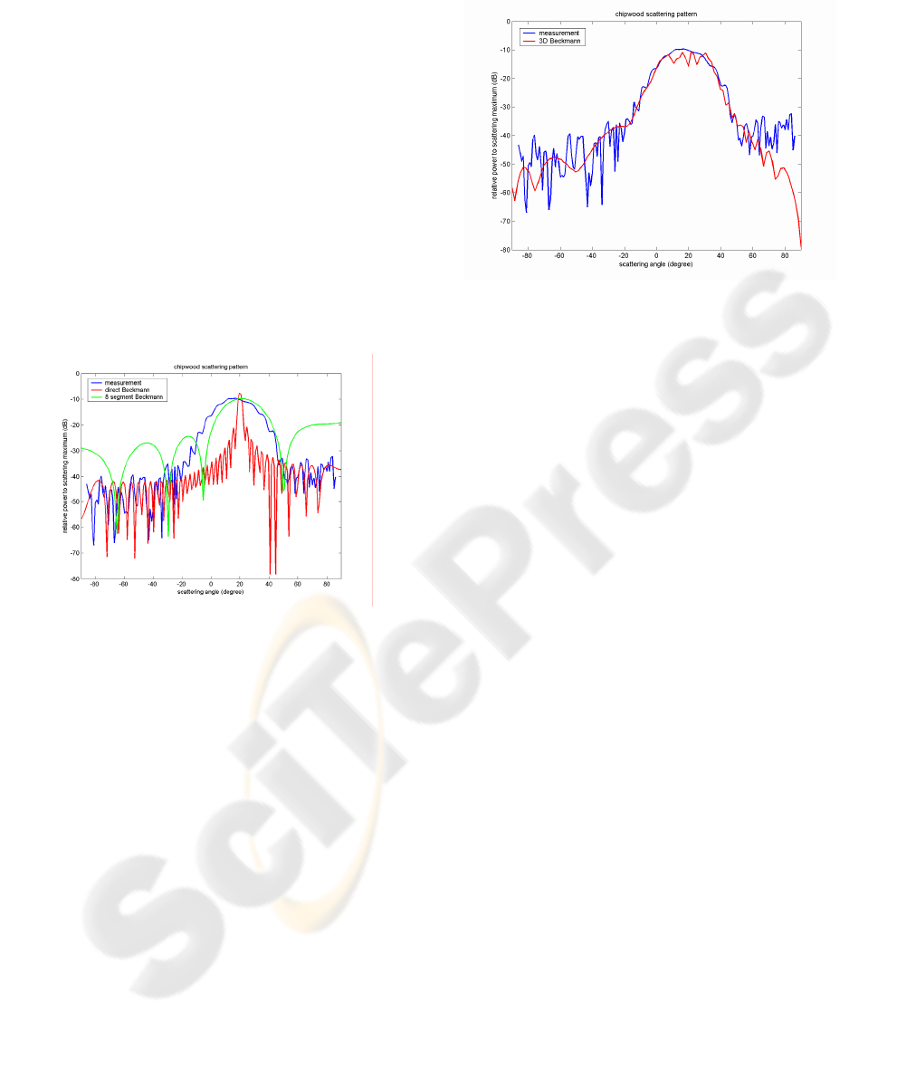
Comparisons among measured scattering patterns
and computed patterns using Beckmann in one step,
by segments, and by patching the illuminated area
are shown in figures 15 and 16. Results indicate
better fitting when Beckmann application takes into
account the geometry of the problem.
Figure 15: Scattering patterns, chipwood panel, parallel
polarisation, incidence 20 degree.
6 CONCLUSION
Results of a measurement campaign of scattering
pattern over flat obstacles are presented. From
measurement outcomes, the involved materials are
electromagnetically characterised in the 5 GHz band.
Moreover, modelling of scattering patterns
generated by flat obstacles is proposed, based on
Beckmann formulation. Among three possible
strategies of implementation, that based on patching
the illuminated area on the obstacle surface, and then
considering local contributions from every patch, is
tested and provides the best results.
Comparison among simulation results and actual
situation measurements show the good behaviour of
the algorithm, the better as the flatter and more
conductive the material is.
As low reflective materials presents reflection paths
in several directions of the incident region,
simulation tools taking into account scattering
patterns instead of just specular reflection will obtain
better predictions.
Figure 16: Scattering patterns, chipwood panel, parallel
polarisation, incidence 20 degree
ACKNOWLEDGEMENTS
This work has been supported by Xunta de Galicia,
Project Ref. PGIDIT05TAM32201PR.
REFERENCES
Arias, A.M., Lorenzo, M.E., Pino, A.G., 1996. A novel
fast algorithm for Physical Optics analysis of single
and dual reflector antennas. IEEE Transactions on
Magnetics.
Beckmann, P., Spizzichino, A., 1963-1987. The scattering
of electromagnetic waves from rough surfaces, Artech
House.
Cuiñas, I., García Sánchez, M., 2000. Building material
characterisation from complex transmissivity
measurements at 5.8 GHz. IEEE Transactions on
Antennas and Propagation, vol.48, pp.1269-1271.
Cuiñas, I., García Sánchez, M., 2001. Measuring,
modeling and characterisation of indoor radio channel
at 5.8 GHz. IEEE Transactions on Vehicular
Technology, vol.50, pp.526-535.
SCATTERING COEFFICIENTS OVER 3-D FLAT DIELECTRIC SURFACES
199
