
MOBILE AND COMPUTER COMMUNICATIONS THROUGH
COLOUR SIGNALS – AN APPROACH NOTE
Rajarshi Sanyal
Reliance Infocomm, Mumba, India
Keywords: Colour Circle, Video BTS / BSC, RGB Encoder , RGB Decoder.
Abstract: The objective of this paper is to discuss a methodology for achieving mobility through colour signals
applicable for wireless networks. The colour is used as the address of the wireless nodes in the network and
for carrying the signaling and the bearer traffic. The present day video systems that can generate millions of
colours, in its electronic form have been utilized for setting up a wireless network, serving mobile stations
or computers as its nodes. A specific colour level is assigned for a user as its address and for exchange of
data. Theoretically, the number of users that can be served by such colour circle has no upper cap, because
the possible colour combinations are virtually infinite. But it is constrained by the sampling frequency of the
available video technologies. The paper provides a basic introduction of the technology and attempts to
compare with the prevalent wireless technologies on various aspects. The technology finds application for
Wireless Computer Networks, Closed User Networks and for Mobile Networks.
1 INTRODUCTION: THE
COLOUR CIRCLE AND
WIRELESS NODES
Isaac Newton said, “Indeed rays, properly expressed,
are not coloured.”
Spectral power distributions (SPDs) exist in the
physical world, but colour exists only in the eye and
the brain. Colour is the perceptual result of light
having wavelength from 400 to 700 nm that is
incident upon the retina. The question is, whether
the colour, generated by the electronic video systems
and perceived by the human retina can be utilized to
render individual / discrete identities to millions of
network nodes which can eventually form a mobile
or computer network.
The nodes of the wireless network for mobile or
computer are represented as specific colour levels in
the colour circle. A band of saturation level is spread
across the colour vector, a sub-band of which is
meant for signaling and the remaining for bearer
traffic. For a mobile network, the coordinate of the
Mobile Station in the colour circle is decided during
provisioning. Similarly, for a computer network, the
IP address (and subnet mask), of the computer or
peripheral decides the position of the node in the
colour space domain. Hence for a mobile or
computer network, the MIN and the IP address
(subnet mask) needs to be a function of the phase of
the colour vector and the band of saturation level for
transcoding voice and signaling.
MIN (E.212 NP) / MDN (E.164 NP) = f (Ø , S
B
) for
mobile network.
IP (Class A, B and C) = f (Ø, S
B
) for computer
network,
Where S
B
=> the band of saturation level allotted to
the user for signaling and bearer data
Figure 1: Space coordinate representation of the Wireless
Nodes in the colour space domain.
Ø
Transcoded
Voice
Signaling
Data
S
B
73
Sanyal R. (2006).
MOBILE AND COMPUTER COMMUNICATIONS THROUGH COLOUR SIGNALS – AN APPROACH NOTE.
In Proceedings of the International Conference on Wireless Information Networks and Systems, pages 73-78
Copyright
c
SciTePress
2 DESIGN BASIS OF A
WIRELESS COMPUTER
NETWORK BASED ON
COLOUR SIGNALS
The basic architecture of a single MAC Colour
Computer network (wireless) provides mobility
within a large Location Area. However, it is also
possible to actuate mobility across multiple MAC
Networks.
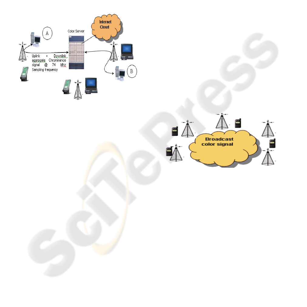
Figure 2: Architecture for Wireless Computer Network.
Node A Initiates to set up a wireless connection with
Node B. It generates a colour train within the
saturation band allotted for signaling (Pat. No.
188052, Govt of India, October 1995).
The signaling data contains the IP Address (Sub net
mask information) of Node A and Node B. The
video repeater, which acts as an access point,
collects the information from various sources,
aggregates as a common Chroma Signal and
forwards it to the colour server. The colour server
receives the colour signals from all the sources (the
repeaters) and forms an aggregate chrominance
signal for the downlink which is broadcast in the
network area. The colour server (which is the heart
of the network and actuates all the virtual routing
functionalities), generates a colour train within the
saturation band allotted for the Node B. The Node B
acknowledges the connection request .The colour
server sets up a semi permanent connection between
Node A and B on the assigned Ø and S
B
for Node A
and Node B, respectively.
Using the HDTV 1080i technology , which has a
colour sampling frequency of 74.25 Mhz (each
colour sample corresponds to a bit) , and assuming
that each wireless node enjoys a forward and reverse
data rate of 2Mbps, the number of simultaneous
users that can be accommodated in a single colour
circle is 37. The deployment architecture can be the
same followed in WLAN where each colour circle
creates a Basic Service Set (BSS) and multiple BSSs
form an Extended Service Set. The Colour server
will essentially perform the functionality of a
Distribition System (DS) which actuates
intercommunication between multiple access points.
The power requirement in the handset to achieve an
uplink data rate of 2 Mbps depends on its distance
with the access point. However, the access points are
inexpensive dumb video repeaters which do not have
any discrete address in the network . Setting up a
colour hot spot will be cheaper and easier compared
to the existing wireless access technologies. Also the
number of the repeaters in the network area can be
increased to minimize the power requirement of the
wireless nodes.
2.1 Network Architecture of a
Standalone PCS Wireless
Network (Closed User Group
and not Linked to External
Legacy Networks)
Figure 3: Network Architecture of PCS network.
The mobile station consists of the chrominance
signal transmitter, which generates colour as a
function of the dialed E.164 number. In a closed user
environment with limited users, the numbering plan
will be fairly simple. Hence the algorithm for
generating the color as a function of the E.164
Number can be housed in the Mobile Stations.
Assuming that we use the HDTV 1080i technology ,
and the digital vocoder transcodes the voice at a
sampling frequency of 8 KHz , the number of users ,
that can communicate in a colour circle
simultaneously in a given network on a single
channel / carrier frequency = 74.25 x 10^3 / 8 =
9280 (HDTV 1080i specifications ). This however
does not take into account the interference factors ,
which will lessen the spectral efficiency to some
extent.
WINSYS 2006 - INTERNATIONAL CONFERENCE ON WIRELESS INFORMATION NETWORKS AND SYSTEMS
74
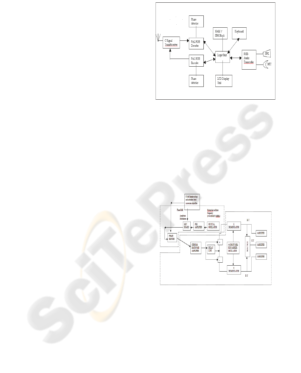
2.1.1 Functional Specification of the Mobile
Station
The Mobile Station will be capable for setting up a
forward and reverse channel with the network for
voice and signaling. It consists of the following
functional blocks (Sanyal, Patent App.No.
0163/MUM/2006 , Govt. of India). The system
components for supporting the supplementary
services are not included.
• NAM & SIM Holder Interface – Number
Assignment module which stores all the
MS related parameters , like MIN/IMSI ,
MDN , Channel Frequency (UHF or VHF)
• Colour Generator and transmitter: Mainly
used for making an outgoing call and to
enable full duplex communication while in
a call.
o E.164 Number to Hue and
saturation level converter for
generation of the colour as a
function of the B Party Number
(Dialed Number)
o Video Encoder
o Phase shifter
o Video UHF/VHF Transmitter
• Colour Receiver
o Video Transreceiver
o Phase detector
• Logic module : to invoke and respond to
different signaling messages and
accordingly decide to make or break the
speech circuit.
• Audio Unit
o Audio PreAmp & AMP
o Audio to RGB transcoder and vice
versa
o AM Bandpass filter
• Keyboard encoder
• Display Unit : LCD display unit
• Power supply Unit
Figure 4: Block diagram of Keyboard encoder.
When a number is dialed, the subcarrier frequency
is passed through an amplitude modulator (to actuate
the saturation level) and is phase shifted (to form
the hue) by a phase shifter to synthesize the desired
C signal which is a function of the dialed number.
The amplitude and the phase are determined by a
logic unit (as shown in the diagram in Fig. 4) which
is interfaced to the keyboard generator (Patent
App.No. 0163/MUM/2006, Govt. of India, February
2006).
Figure 5: Keyboard Encoder for PCS Mobile Station.
MOBILE AND COMPUTER COMMUNICATIONS THROUGH COLOUR SIGNALS – AN APPROACH NOTE
75
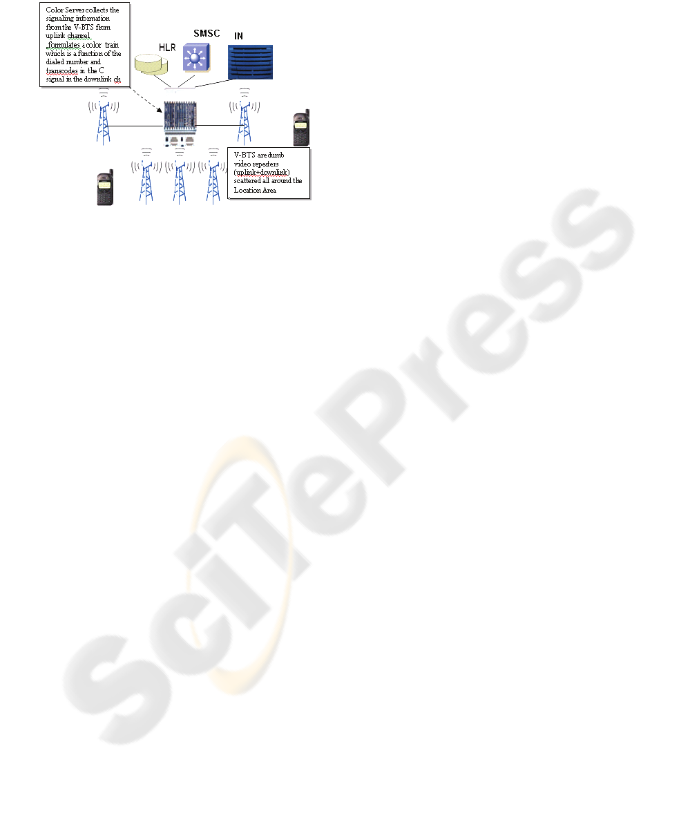
2.2 Deployment Architecture for a
Mobile Network
Figure 6: Mobile Network on Colour Signals.
Each Color Circle pertains to a single Location area
and not subdivided into multiple orthogonal cells, as
is present in the existing technologies like GSM or
CDMA . The BTS is replaced by Video
Transreceivers (termed as V-BTS ) placed all over
the network coverage area which can establish an
uplink and downlink channel in UHF / VHF with the
handsets (Sanyal, Patent App. No. 0163/MUM/2006,
Govt. of India). The chrominance signal transmitted
from the V- BTS is primarily a broadcast signal
containing colour information , sampled at a
specific frequency ( for HDTV , the sampling
frequency if 74.25 Mhz) for all its users in a given
network coverage area. Each handset after receiving
the chrominance signal demodulates it and filters out
the colour signal (in terms of R – G – B Levels )
pertaining to the specific hue and the band of the
saturation level in digitized form. Within the specific
band of the saturation level allotted for the
subscriber , say Band A (ranges 10% to 35 % ) , a
specific sublevel say Band A1 carries the signaling
information (for paging , Alert with Info , etc) and
the Band A2 , carries the digitized voice
information. The heart of the network is a colour
server which processes all the colour information.
The colour server interoperates with the MS through
the V-BTS / V-BSC and exchanges the SS7
signaling information with the core network
accordingly. The speech circuit between the A and
the B party is established over the band of saturation
level tied up with the colour level that has been
assigned for both the parties.
The functional specification of the mobile station is
the same as that show for the CUG PCS network,
except for the fact that the Keyboard encoder does
not need to hold the algorithm which ports the dialed
E.164 number to color generator. This function
instead exists in the colour server .
The primary functions of the colour server are the
following.
1. Performs all the colour signal processing for the
access network
2. Formulates the colour train which is a function
of the dialed E.164 mobile number (of the same
serving market).
3. Performs the Signaling operations (on SS7) with
the core network
4. Interoperates with the V-BTS/V-BSC for the air
interface related operations.
5. Interfaces with the Legacy Networks (on
associated mode of signaling and PCM Voice
trunks on F Links and on A links on quasi
associated mode ).
6. Call Data Record generation for Mediation /
Billing
7. Call routing for the legacy network
8. SSP Functionality for Intelligent network
operations
9. Supports Supplementary Services
2.2.1 Advantages
¾ Eliminates the need of complex time and space
switching matrix present in modern days mobile
networks.
¾ No need of frequency re-use , needs lesser
number of channel frequencies compared to
GSM or CDMA.
¾ No need of complex planning of macro / micro /
pico cells. Coverage area can be split up into
broader areas and scattered with Video
Repeaters .
¾ Instead of increasing the number of cells to
increase coverage, as in GSM/CDMA , it is only
required to add more inexpensive video
repeaters to increase the size network area ,
until the maximum number of subscribers that
can be catered by a single color server is not
reached. Power Requirement of the Mobile
Station depends on the number of repeaters
placed in the coverage area. No power misuse
due to increased signaling, as in GSM or
CDMA.
¾ Signaling overhead is much less , resulting in a
cheaper network. No complex handoff
mechanisms required (like soft handoff or hard
handoffs) or other operations related to mobility
management.
WINSYS 2006 - INTERNATIONAL CONFERENCE ON WIRELESS INFORMATION NETWORKS AND SYSTEMS
76
¾ Reduction in the backhaul / transport. The calls
within the same V-BTS can be processed
locally and need not be taken towards the colour
server .
¾ Faster deployment, low maintenance cost of the
network, less manpower required for operations.
¾ Can be built upon the existing television /cable
TV network . Satellite transponders meant for
video communication can also be used for voice
and data.
The following study shows a comparison of the
proposed technology for mobile networks and GSM
in terms of the network capacity and spectral
efficiency.
2.3 Capacity Calculation
In GSM, the radio spectrum in the bands 890-915
MHz for the uplink (mobile station to base station)
and 935-960 MHz for the downlink has been
reserved in Europe for mobile networks. The uplink
and downlink band , each of 25 Mhz , is divided in
124 channels. Each of the 124 channels can support
8 separate connections with one time-slot per
connection . Theoretical limit of 124 channels x 8
connections per channel = 992 connections per cell.
But, many frequencies in any particular cell are not
used to avoid conflicts with neighbors, resulting in
much reduced support of simultaneous calls.
Capacity in terms of Call Connections per Mhz of
Bandwidth in GSM = 992 / 25 = 40 or lesser.
Span of a cell in GSM = few Kilometers radius. Size
is constrained by technology.
The 1080i HDTV theoretically requires a 37 MHz
video bandwidth. Sample rate for 1080i HDTV is
74.25 Mhz. The subscriber’s speech will be
transcoded through the VOIP codec, which requires
a sampling frequency of 8khz (data taken for VOIP
Codec specification). Simultaneous calls supported
= 74.25Mhz / 8 KHz = 9280.
Capacity in terms of users per Mhz of Bandwidth =
9280 / 37 = 251.
Span of a cell = An entire coverage area can be
made up of a single cell, and size of the cell is not
constrained by technology , the determining factor
being the call attempts that is required to be
supported.
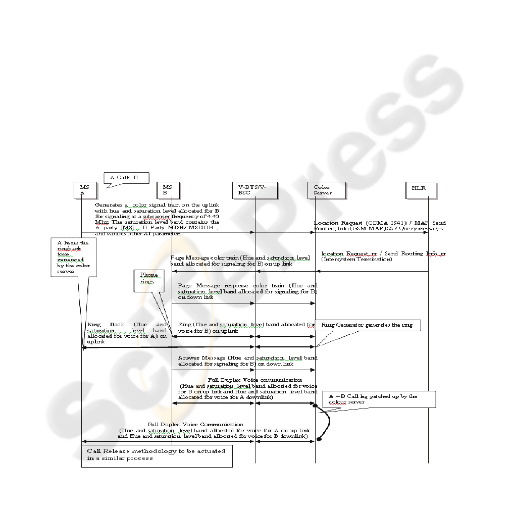
Figure 7: Call flow for a call initiated by the A party towards the B party is shown below (ANSI 41 – D Specification / ITU-
T MAP 2 Specification).
MOBILE AND COMPUTER COMMUNICATIONS THROUGH COLOUR SIGNALS – AN APPROACH NOTE
77
3 EXPERIMENTAL SETUP FOR
VOICE COMMUNICATION ON
COLOUR SIGNALS
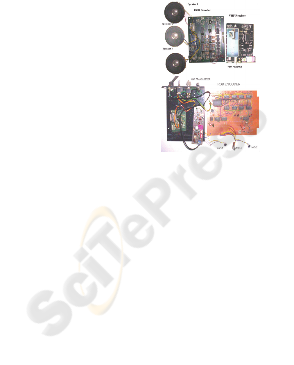
The experiment was performed based on the primary
colours (Red , Green , Blue) .With the setup, three
VHF colour transmitters ,each capable of
transmitting red , green and blue colour levels
respectively were transmitting modulated Saturation
level (voice transcoded to colour with the aid of a
suitable driver) on these basic colour levels (RGB)
.The receiver decodes the three different voice
signals transmitted on the three basic colour levels
and feeds the signals to three different speaker
outputs. The audio output in each channel was
distinct with no distortion.
The phase and the voltage of the basic color signal
(RGB ) are determined by the following equations.
The equation of the illuminance signal (Y) is
Y = 0.30 R + 0.59 G + 0.11 B
Hence R-Y = 0.7R - 0.59G - 0.11B
R –Y is maximum when G and B are 0.
Similarly , B-Y = 0.89B – 0.59G – 0.3 R
B-Y is maximum when G and R are 0.
When there was no audio input , and hence no signal
pertaining to the Green and Blue section , and when
a constant voltage output of 1 volt was obtained
from Red color output (in the chroma section of the
video transmitter) , the Magnitude of the composite
chroma signal is |C| = √ (R-Y)
2
+ (B-Y)
2
= 0.7v
The phase angle of the color vector , in that situation
which governs the hue is
Φ = tan
-1
(R-Y) / (B-Y)
= - 66.80
O
REFERENCES
Sanyal, Rajarshi, 1995. A system of wireless networking
of computers in the UHF”, Patent
Document (Pat. No. 188052, Govt of India, October
1995)
Sanyal, Rajarshi, 2006.Framework for Realizing Mobile
Network Through Colour Signals. Patent App.No.
0163/MUM/2006, Govt. of India, February 2006).
ANSI 41 – D Specification / ITU-T MAP 2 Specification
HDTV 1080i Specification
Figure 8: Triple Audio Receiver and Transmitter on Basic
Colour Signals (RGB) as carrier signals and built upon
PAL VHF Transmitter and Receiver.
WINSYS 2006 - INTERNATIONAL CONFERENCE ON WIRELESS INFORMATION NETWORKS AND SYSTEMS
78
