
VARIOUS PROCESS WIZARD FOR INFORMATION SYSTEMS
Using Fuzzy Petri Nets for Process Definition
Jaroslav Prochazka, Jaroslav Knybel, Cyril Klimes
Department of informatics and computers, University of Ostrava, 30. dubna 22, Ostrava, Czech republic
Keywords: Process, workflow, wizard, process wizard, Petri net, fuzzy Petri net, IF-THEN rules.
Abstract: The new approach in information system automation is process or workflow management. For unskilled
user is important, when the business processes of company are described. Then, according to this
description are users led correctly in their work. The business (application) model can be caught in finite
state machines and its variations. Petri net can be used for process definition in process wizard. Sometimes
unclear state occurs, for its description can be fuzzy logic IF-THEN rules used. We explain what process
wizard is, what should contain and outline how it could be implement in IS QI. We also introduce Petri nets
with fuzzy approach for process description.
1 INTRODUCTION
Today’s open global market changes the nature of
business. Company that wants to be able to compete
must leave traditional organization structure and not
convenient leading methods. Company should be
focused on customer and should be managed by
market requirements. From an inner point of view,
company should focus on processes and team
cooperation. The base of all these changes is the use
of (new) information technologies. The processes
are the roots of every working organization. Modern
organization that wants to be able to compete on
market in global society should be based on
automation processes (Carda, Kunstová, 2001).
Workflow means whole or part automation of
enterprise process, during which are documents,
information or tasks handed over from one process
participant to another, according to a set of
procedural rules so, that it contributes the
performance of global enterprise objectives.
Workflow system defines, creates and manages the
process flow. This system is able to interpret process
definition, communicate with workflow participants
and if needed, run other applications (Hollingsworth,
1994). As a real workflow system, we consider the
one that provides:
– Graphical workflow design, which defines the
flow of tasks and activities, roles to activities.
– Rules defining the logic of process without
programming.
– Exception solving.
– Monitoring of process instances, measurement.
– Process simulation, testing, statistic reports.
– Database interface (from its IS).
– Document affiliation.
Enterprise infrastructure is set up by combination
of its processes. Unfortunately is this infrastructure
not completely described and documented, because
the major part are advances designed and held in
employees heads or are overspread through different
directives or are respected as an informal rules.
Some of them are between employees handed on
oral form. Any improvement or extension demands
infrastructure documentation first.
In recent state the process support in information
systems is not spread. There exist several solutions
on the market, where user can define company’s
processes and these definitions join with information
system’s functions. Such system can show, what was
previous process step or user can see possible
following steps according to current process state.
One of these tools is IS SAP and process tool ARIS,
other one is e.g. Baan IS. QI IS also contains support
for process management.
Unfortunately process or process participants can
include elements that are not clear. When we use
strict process definition, we are not able to capture
these elements. One approach how to include
unclear elements into process description is the use
of fuzzy approach.
235
Prochazka J., Knybel J. and Klimes C. (2006).
VARIOUS PROCESS WIZARD FOR INFORMATION SYSTEMS - Using Fuzzy Petri Nets for Process Definition.
In Proceedings of the Eighth International Conference on Enterprise Information Systems - AIDSS, pages 235-242
DOI: 10.5220/0002441102350242
Copyright
c
SciTePress
Useful tool for process (workflow) management
is process wizard. This tool can lead user through
whole process according to his operations and
current system states.
Our research intention deals with process wizard
design for QI information system, so some practical
samples are shown in IS QI, but majority of
appointed ideas is usable generally. This paper is
promoted by research intention DAR of Czech
academy of science 1M6798555601.
1.1 QI and Processes
As said, QI information system contains also
implementation of workflow. Nowadays, in IS QI is
implemented process management without
possibility of automatic IS functions call. We briefly
introduce technological solution of QI system
function (form) implementation. Data is stored in
database. This database is only storage; it does not
implement any functions. Stored data does not make
sense at all, for the sake of security. The most
important part is application server (AS) – here is
data collected together. AS consists of data interface,
object server and stores application logics as well.
Application forms display user data. Important
component, which defines data in form, is called
data set (DS). It is user defined selection set and
represents part of application logics as well.
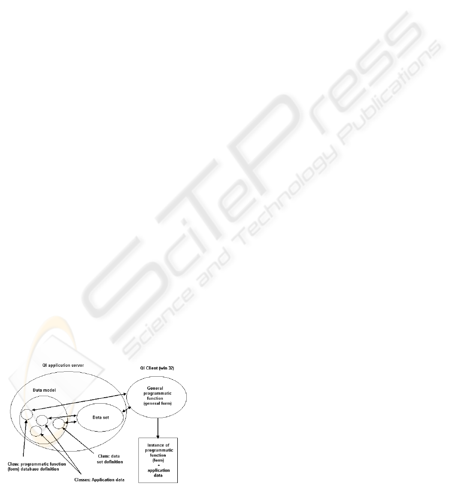
Win client comprises general programmatic
functions implementation (general form, general
report – so called functional objects). DB stores not
only user (application) data, but also concrete form
and report definitions – their size, position, included
components (buttons, fields, etc.), and connected
data sets. Before the called form is opened, the
general function of win client has to ask application
server for these definition data. This implicates, that
called form must exist, must be created first. QI
architecture depicts following figure 1.
Figure 1: QI application technology.
If we want to automate the process as deep, that
the system functions will be opened (generated)
automatically, there have to exist several variants of
given functions (forms) for each branch of process
or for different processes. Let us introduce an
example. One bill form with appropriate checks and
data fields is necessary for insertion to system. Other
one (with quite different checks and fields) we need
for supervisor’s authorization. It denotes, except
complete process description, to develop all possible
variants of programmatic functions (forms and
reports) that can be used in processes. Such
approach is neither effective nor practicable.
Besides, any change in process definition brings
revision of all programmatic functions supporting
this process. Therefore is our aim to design wizard
to generate called programmatic functions
automatically according to given templates or
patterns with possibility of user modification (what
data can user see and use).
2 PROCESS WIZARD
This chapter introduces what the wizard is, and what
are its features. The name could in reader invoke
mighty capability, but in IT, the wizard is usually
called a program or a component, which helps user
or developer to create or finalize some document,
application class, application component, form or
anything else. This is done step by step and it has its
beginning and its end.
We can define software wizard as component
with following qualities:
– All wizard data compose a single transaction.
– Steps are processed in sequence from given
beginning to given end.
– There exist one starting step, several
intermediate steps, and one ending step.
– The wizard validates its state before advancing
to the next step.
– There can be several different paths to reach the
ending step.
– It is possible to navigate back to review and
update values entered in previous steps.
– A wizard can be cancelled before completion.
QI process wizard should lead user through
whole process or through its important part. Every
form is based on given data set (DS), if there is more
than one DS included in form, there should be
hierarchy or synchronization of data sets. These
hierarchies and synchronizations have to be included
ICEIS 2006 - ARTIFICIAL INTELLIGENCE AND DECISION SUPPORT SYSTEMS
236

into wizard as well. From above facts result
fundamental assumptions for process wizard. For
dynamical form generation according to valid
process, we need:
1. Process description – description of application
domain, for this purpose can be used Petri net or
finite state machine (FSM).
2. User defined data – this is, what user want to
see, update or validate.
3. List of relevant DS (which can be used for given
form) including their hierarchy and possible
synchronizations.
4. Storage for application data and for model data
(process description) as well.
We come up from stored process description, user
defines application data, which he/she wants to work
with, then is generated (dynamically created) form
that matches all given requirements. Storing
mechanisms are already included in IS QI and also
are in all other IS.
Let us shortly discuss item 1. Formalisms based
on FSM are often used for process description. But
there exist also other tools for process modelling in
IT, namely UML activity diagrams, BPMN
(Business Process Management Notation), ARIS
notation and many others. One of our arguments,
why we have chosen Petri net for process modelling
is that these tools mentioned above do not have
mathematical apparatus as Petri nets do. The second
one is possibility of use fuzzy Petri net for unclear
process definitions. We used paper (Boerger, 2002)
for our decision-making as well. Chapter 3 deals
with process description and Petri nets.
We use in process wizard known and usual
approaches and technologies, these are Petri nets and
automatic code generation. Asset of our solution is
using them all together and also inclusion of fuzzy
approach into enterprise process modelling. Using
this solution, no UI screen forms need to be pre-
defined (implemented), they are automatically
generated whenever needed. Only templates for
generation have to be defined (see chapter 4.1). This
brings advantage for application customisation and
for change implementation. We believe that variable
visual process description and automatic generation
of UI screens and functions is better than to lock
processes into application code.
For user steps automation is process model
(description) used. User is led throughout his/her
working procedure. Thanks to fuzzy approach it is
possible to automate also some system decisions
where user otherwise should make decision. So it
brings more automation into information system.
But user can be still the one, who manages
application.
2.1 MVC Model Architecture
To insert concepts said in this paper to IT
architecture, we use really known MVC model. This
technology was first used in Smalltalk programming
language class library. It is typically used in user
interface (UI) programming, and it is also known
from Java Swing class library. Though this
technology is older than 20 years, it is still often
used in IS and web projects. Basic technology
feature is implementing program component using
three following classes:
– View: this object represents visual graphical
component.
– Controller: catches inputs via graphical
component and reacts on it (perform action on
model and view). Controller is binding between
model data and their graphical representation.
– Model: object represents graphical component
data (domain model).
Using MVC technology for implementing user
interface, it is common, that model is shared
simultaneously by more than one graphical
component (e.g. same data can be in textual grid
form but also in a graphical tree form).
In our case, the wizard, user works with, is a
view (the graphical component). Wizard can contain
also controller, which handles all user inputs and
perform these changes on model.
When we come back to the beginning of this
chapter and read once more the 7 points, which
define wizard, we realize, that model of wizard
should be a directed acyclic graph with weighted
edges. Model represents this graph with a modified
adjacency list. Each node of the graph corresponds
to one wizard step. A node either refers to or directly
stores domain data relevant to the step. Besides that,
a node holds references to the adjacent nodes.
Directed graph G is a pair G = (V, E), where
V = {v
1
, v
2
, …, v
n
} is a set of points called vertices
or nodes
E = {e
1
, e
2
, …, e
m
} is a set of lines or curves called
edges.
A directed acyclic graph is a graph with no
directed cycles. That is, for any vertex v, there is no
directed path starting and ending on v.
Using marked edges, we can describe every path
through graph. There exist several ways, how to
VARIOUS PROCESS WIZARD FOR INFORMATION SYSTEMS - Using Fuzzy Petri Nets for Process Definition
237
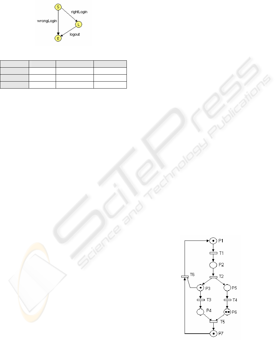
describe it. One is a list of names of edges; the
second one is a matrix or a table (see following
example, figure 2 depicts graph described by table).
Figure 2: Graph for login path.
Start (S) Login (L) End (E)
Start (S) rightLogin wrongLogin
Login (L) logout
End (E)
It is important to stress, that terminology of
graph theory is not unified, so above written
definitions can be little bit different from these
reader knows (Demel, 2002).
3 PROCESS DESCRIPTION
It is possible to describe application domain or
process transitions using finite state machines
(FSM). They are strictly formal and have
mathematical apparatus, thus they are suitable for
process modelling, simulation and automatic
generation. Although FSM is really spread, it has
several limitations, namely parallelism modelling,
distribute system modelling and huge state amount
for complex process description. Consequently
another formalism based on FSM is used: Petri nets.
Petri net concept is known from 1966, for
detailed description see (Peterson, 1981). This
concept comes out from decomposition of system to
subsystems described by finite state machines. These
machines work independently, but can be
coordinated. From its beginning, Petri nets has come
a long way, and nowadays are intensively studied.
Petri nets are used mainly for analysing, designing
and modelling parallel and distributed systems as
well as for parallel architecture description, compiler
or computer net description or programming
languages semantics description. Petri net is a
special biparital graph. It is composed from several
types of elements:
– Places: are used for expressing modelled system
states; circle usually represents places.
– Transitions: describe system changes; places are
usually represented by rectangles.
– Arcs: are unconditionally oriented and connect
place with transition or transition with place. Arc
cannot connect two places or two transitions.
Every ordered pair (place, transition) or
(transition, place) can be at most connected by
one arc. Arcs are usually represented by arrow.
– Inhibitory arcs: are special sort of arcs, this arc
can connects given place with chosen transition.
Inhibitory arcs are usually represented by line
with circle on transition’s side.
– Marking: represents actual system state using
tokens. Token is depicted by small circle and can
be used only in places. Every place can have
given number of modelled system tokens.
System states are modelled by mark flow. Initial
system state is usually called M
0
.
Formal definition for Petri net (sometimes called
P/T Petri net as Place/Transition) is following. Not
marked Petri net is a senary:
PTN = (P, T, A, IA, AF, IF)
Where:
P is a finite non-empty set of places
T is a finite non-empty set of transitions
P ∩ T = ∅ (their intersection is an empty set)
A ⊆ (P x T) ∪ (T x P) is a finite set of arcs
IA ⊆ (P x T) is finite set of inhibitory arcs
AF: (A ∪ IA) → N is an arc function
IF: P → N
0
∪ {ω} is initialisation function.
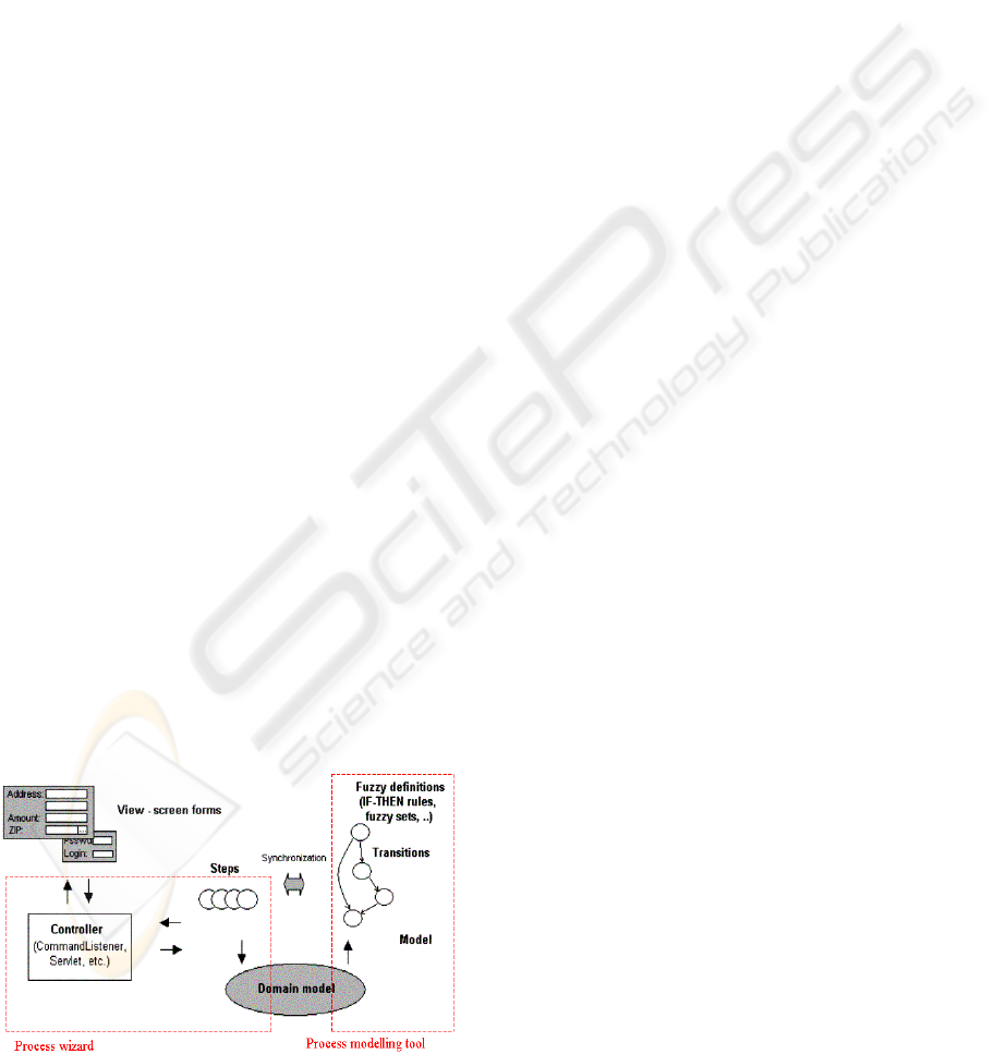
Figure 3 depicts example of Petri net with places P1,
P2, …, P7 and transitions T1, T2, …, T6, there
exists also inhibition arc (P3, T6). We can describe
initial net marking using given ordering by seven (1,
0, 1, 0, 0, 2, 1).
Figure 3: Petri net example.
ICEIS 2006 - ARTIFICIAL INTELLIGENCE AND DECISION SUPPORT SYSTEMS
238

As we said above, we can extend Petri net
concept with unclear (fuzzy) elements for the
purpose of process modelling. When modelling
process sometimes we need depict state, which we
do not know if occurs or not (so called vagueness
phenomenon). Standard Petri net expresses states
using tokens. Token is included into place, if given
expression is true (1), if false (0), token is not
included. How to model unclear state? We can
employ fuzzy values (“small”, “much”, “middle”,
etc.) into Petri net. To work with these values we use
fuzzy logics, specifically IF-THEN rules. There
exist several ways, how to combine Petri nets with
fuzzy sets (Cardoso, Camargo, 1999). In one of
them, the net models reasoning systems. The
components comprise knowledge representation,
most of the time the transitions are associated with
fuzzy rules and the whole net depicts an expert or
control system (Chen, 1999, Gomes, 1999). The
second general approach devotes to the modelling of
dynamic physical systems and the transitions denote
possible state changes (Cardoso, 1999, Kunzle et al,
1999).
Our approach includes fuzzy logic by following
way. Token holds fuzzy set definition, arcs are
evaluated by natural language expressions and
finally transitions represent fuzzy relation
corresponding to given IF-THEN rule. Relation
creation depends on chosen inference method.
Closer explanation of inference methods is out of
range of this paper, for more information see
(Dvořák, Habiballa, Novák, Pavliska, 2003).
Fuzzy Petri net extends Petri net formal
definition with:
– D: set of expressions
– h: P → D function represents relation place –
expression
– a: P → [0, 1] function represents place value
–
θ
, l: T → [0, 1] functions represent value
transition.
Let us introduce an example to clarify binding
between fuzzy IF-THEN rule and structure of fuzzy
Petri net. Our example records situation, when
subscriber wants to buy a lot of goods (costs a lot)
and has huge debit (not more than we tolerate),
system should make decision if sell everything or
not. IF-THEN rule will look like:
IF D is huge AND R is huge THEN P is low
Where: D is subscriber‘s debit
R is subscriber‘s purchase request
P is our permitted purchase amount
Following figure 4 depicts given fuzzy Petri net.
Figure 4: FPN implementing IF-THEN rule.
In outlined example system allows only low
amount purchase according to defined IF-THEN
rule. From this example is obvious that the system
can decide what to do without a human intervention.
System’s decision is based only on IF-THEN rules
and current values (D, R).
Petri nets are applied in many IT and automation
fields. We use Petri nets as a formal visual tool for
process modelling. Using fuzzy Petri net is possible
to shift decision making on system in some cases.
That is the reason, why we include fuzzy Petri net
into process modelling tool.
How to implement (source codes or approaches)
Petri nets even fuzzy Petri nets is out of the scope of
this paper, see e.g. (Dvořák, Habiballa, Novák,
Pavliska, 2003).
4 WIZARD DESIGN
As said above, Controller has to change model
according to user changes and user interface and
application data according to changes in a model.
Model (process) is represented by directed acyclic
graph. Each node of the graph corresponds to one
wizard step. A node either refers to or directly stores
domain data relevant to the step. Besides that, a node
holds references to the adjacent nodes (previous
nodes and possible following nodes). Wizard node
class should contain functions for:
– Adding outgoing edge of node (node can have
more than one outgoing edges),
– Returning the outgoing edge chosen for forward
transition,
– Storing and returning incoming edge used for
reaching current node, it is used for backward
transition,
– Validation (if node holds) – returns valid edge.
All nodes refer to application domain data. This
data is stored in a database, so Node class should
VARIOUS PROCESS WIZARD FOR INFORMATION SYSTEMS - Using Fuzzy Petri Nets for Process Definition
239
contain functions also for storing, loading and
validating data (e.g. right format, not empty values).
Besides this, each wizard step is UI screen form to
be generated and should depict application data.
Which screen form should be generated is defined
also in process model. Templates describe form
structure, controls and synchronizations. Each
wizard step need input data validation, if there is
anything wrong taking into account domain model
standing, the wizard does not traverse to another
step. Everything is again defined in wizard template
(see chapter 4.1). The last wizard step is
confirmation. Confirmation node does not define
any properties; it only applies wizard data to the
application domain model, when the wizard finishes.
The whole wizard transaction is then performed on a
domain model.
An edge defines the path from one wizard step to
another and holds the references to its source and
target nodes. An edge class should implement the
following important functions:
– Get source node for an edge,
– Get target node for an edge,
– Validation (if edge holds) – returns true if
forward move is allowed.
The wizard controller class should implement
following important functions:
– Get source node and current node,
– Get possible forward and backward traverses
(for moving to next or previous node).
We outlined wizard main functions. These are
edge validation rules, traversal commands, node’s
edge list and node and model synchronization. But
for our purpose and for user-friendly usage, we need
corresponding user interface (UI). Situation of
solution architecture depicts figure5
Figure 5: wizard architecture.
4.1 Implementing Wizard to QI
There exist two approaches how to implement
process wizard to QI information system. The first
approach is a complete generation of a UI screen
form (we need to work with) using templates. Screen
form is automatically generated always, whenever
called. The second one uses complete existing form
with marks. When user calls form, only specified
parts are shown, using marks. First we need to
examine the object model of QI, if there exist
appropriate objects for process wizard. Basic data
set dealing with processes and workflow in QI
information system is Workflow DS. The core of
this DS is object Process, this has relation to
Programming function object. Process wizard is a
software component, which reads the Petri net state
and calls/generates programming functions or its
subclasses according to the state (understand,
according to process description), see figure 5.
Process wizard is a component without its own
separate data objects; it reads existing ones. Because
of this fact, we do not need alter data model or data
sets. Now we can discuss 2 mentioned approaches.
The first approach – complete generation using
templates – has some prerequisites. We need to
group all possible data sets with abstract forms or
with processes. This step is important to reduce the
set of valid data sets. Why use all data sets, when the
bill form uses only customer data set, bill data set
and bill items’ data set. If we don’t do this, we can’t
prepare DS synchronizations. We use process
approach, it means only necessary data is shown and
used in every moment user performs the process.
Other data is neither requisite (shown) nor
accessible. That is one of process approach
advantage. It results the necessity of only reduced
count of data sets (only valid ones) at given process
step. For form design and element positioning are
used templates. Following example shows possible
structure of a template.
<form name=”Bill” title=”Bill-In”>
<container name=”Cust” DS=”Cust”>
<column title=”Name” field=”Name”>
<column title=”Pay” field=”Pay”>
<column title=”Amount” field=”Amount”>
</container>
<container name=”Items” DS=”Item”>
……
</container>
<synchronization>
……
</synchronization>
ICEIS 2006 - ARTIFICIAL INTELLIGENCE AND DECISION SUPPORT SYSTEMS
240
<control>
<column=”Amount” cType=”NOT-NEGATIVE”>
</control>
</form>
Container is a logical part of a form that can be
visually divided by line, empty space or by
bookmark. Generator (wizard) reads these templates
and generates required form using data from valid
data set. These templates can also contain sections,
where the data set synchronizations can be defined
as well as data controls (control section, the type of
control defines attribute cType, here the amount is
not allowed to be negative). This approach needs to
design all templates and implement into wizard
generative mechanism.
Second approach deals with existing forms, so
this doesn’t solve our objectives, but it is also one
possible approach. We need to design and
implement complete maximal forms with marks.
These marks are applied also on controls and data
sets together with synchronization. If no field from
DS is used, complete DS is used neither. Controls
are joined with particular fields. When we don’t
include field, control is included neither. Using this
approach we can simply solve data set
synchronizations and data controls. Controls and
synchronizations are in current application designed
by experienced engineers; it is not easy to automate
this step. Finally, calling the form is a sort of
customisation. Before calling form, we only need to
specify which marks use. This can we specified
directly in process description or by user while
operating. Final “generated” form has only data user
needs. The problem is that we need to design all
forms supporting company’s processes before using
application. These states of application are presently
almost the same only difference is the use of marks.
Wizard based on both approaches reads current
state from Petri net; it means the process description.
According to this description wizard calls
programming functions, this means calling marked
form or generating required form using template.
Wizard methods mentioned above should be
provided by formal mechanism (Petri net) and
should be provided via interface.
4.2 Process Modelling Tool
Process wizard and process modelling tool are two
different components. They can be implemented
together, but conceptually are two different modules
(subsystems), see figure 5. The first one – wizard is
designed for screen form calling. It can call existing
ones or generate them completely. We have
designed process wizard working prototype and now
we are finding the ways, how to implement
modelling tool. Process modelling tool supplements
wizard providing formal mechanism for process
modelling or description. Such mechanism catches
the process model and provides current state to
wizard via some interface. This interface can be
functional (functions or methods are invoked to
detect state) or data (states are handed over data).
As said process description encoded into formal
tool is read by process wizard and according to its
state is given form called or generated. Formal
mechanisms that are used for this purpose are FSM
or Petri nets. We have chosen Petri net for process
modelling because it has strict mathematical
apparatus that can be used for simulation and
algorithm modelling. The second reason was
possibility of use fuzzy Petri net for unclear process
definitions.
The first design issue is to map all process
elements to Petri net. It means that activities,
participants, sources (PC, people, money, machine),
documents (bill, contract, directive, guideline) and
all its relations have appropriate position in Petri net.
For example activity can be represented by place,
and when place includes the token, activity is
performed. This task we need to do before we
include fuzzy elements to Petri net (before we use
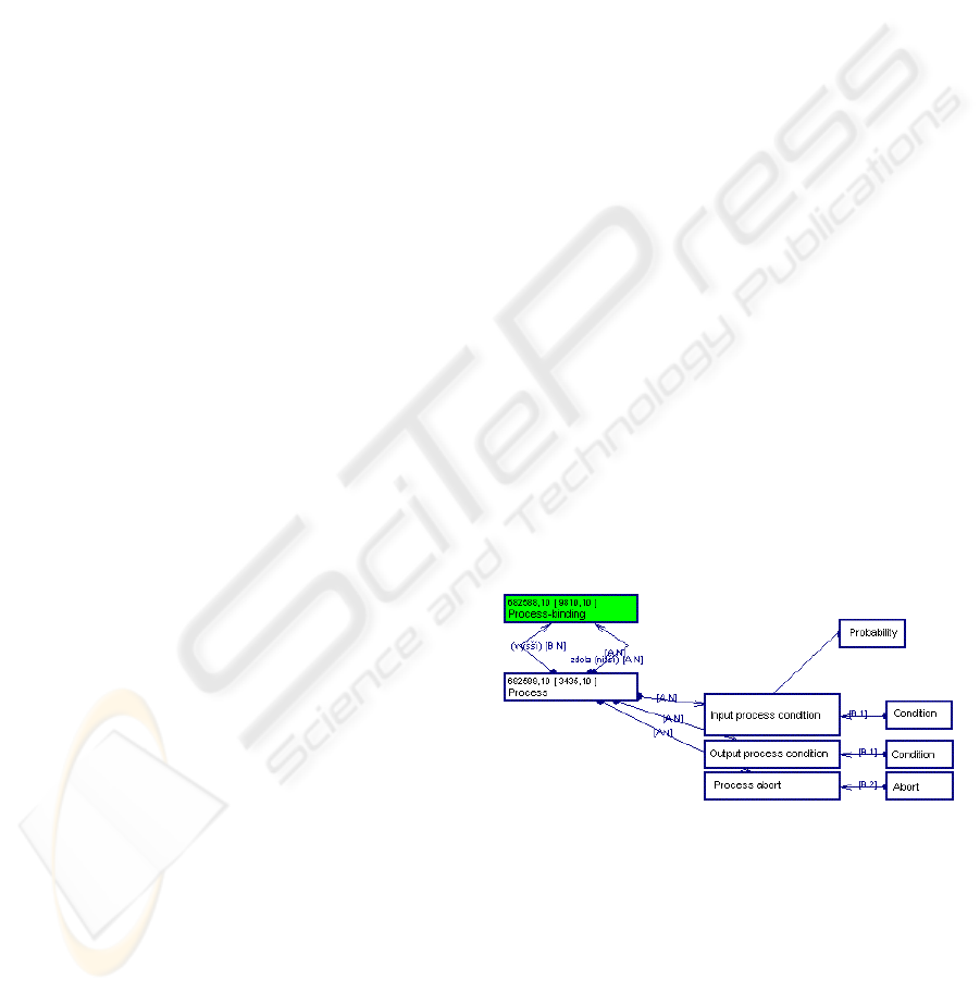
fuzzy Petri net). As we said above that the main data
set is the one called Process. We need to alter it to
include artefacts of Petri net. System should know
when can activity starts, when it ends, activity can
be also aborted without finishing etc. We introduce
new objects for these situations; see figure 6.
Figure 6: Fragment of Data Set Process.
Other design issues deals with inclusion fuzzy
elements to information system, mainly how to
represent fuzzy sets and rules, how to store them and
how to put all these elements together. We are
dealing with the use of existing LFLC system
developing at our university by team of professor
Novak. It can communicate with IS via XML. Other
solution is to implement it directly into information
system. Here are listed some fuzzy design issues:
VARIOUS PROCESS WIZARD FOR INFORMATION SYSTEMS - Using Fuzzy Petri Nets for Process Definition
241

1. Representation and data structure for fuzzy set.
2. Definition of IF-THEN rules.
3. Storing mechanism for fuzzy sets and rules.
4. Defuzzification (methods for defuzzificaton).
How to define data structure for fuzzy set is
fundamental part of solution. Using Process DS
there is possibility to represent fuzzy set as a normal
set with list of natural language expressions.
IF-THEN rules can be easily represented as
programmatic function – macro. Macro is a code in
IS QI macro-language, which is used for
programming controls and complex functions that
cannot be easy implement by using analytics
modelling. There exist several types of macros in QI
(client or AS macro, field or form macro, etc.) We
can write IF-THEN rule as a simple macro with a
new type RULE. Thanks to Process object and
Programmatic function object relation is ensured
connection between rules and Petri net. This can be
easy solution for first two issues.
The third issue deals with storing fuzzy sets and
rules. Both mentioned solutions use only system
parts and system tools (programmatic function, data
set, macro), thus are storing mechanisms already
implemented.
The last issue is defuzzification. For its
implementation advance, we can again use macro
that defines mathematical formula for getting
number from fuzzy set (centre of gravity, least of
maxima or mean of maxima).
5 CONCLUSION
This paper deals with workflow and its automation
in information systems. We briefly described QI
information system and a vision of a process wizard.
We outlined our objectives, process description
using formal tool (Petri net), wizard functions and its
design issues using MVC architecture.
We believe that the process automation and
automatic generation is the way, how to easy adapt
system for different users and implement changes.
While modelling process, unclear states can occur.
This is not possible to model by strict Petri net, thus
we introduced fuzzy IF-THEN rules and fuzzy Petri
nets. Fuzzy Petri nets can also automate some
decision making without a human intervention.
The last part deals with possible solutions for
process wizard and process modelling tool. The first
wizard solution is based on generation using
templates; the second one is based on existing
marked forms customisation. Process modelling tool
(Petri net) design issues are listed also, together with
fuzzy elements inclusion issues. Possible solutions
for QI information system were outlined.
REFERENCES
Boerger, E., 2002. Computation and Specification Models:
A comparative Study. In. Seminar on Theory and
application of abstract state machines. Dagstuhl.
Burbeck, S., 1992. Applications programming in
Smalltalk-80: How to use Model-view-controller.
ParcPlace.
Carda, A., Kunstová, R., 2001. Workflow: enterprise
process management. Grada. Praha, 1
st
edition.
Cardoso, J., Camargo, H. (Eds.), 1999. Fuzziness in Petri
Nets. Physica-Verlag.
Cardoso, J., 1999. Time Fuzzy Petri Nets. Fuzziness in
Petri Nets. Physica-Verlag.
Chan, S., M., 1999. Knowledge Base Verification Using
Fuzzy Petri Nets. Fuzziness in Petri Nets. Physica-
Verlag.
Demel, J., 2002. Graphs and its application. Academia.
Praha, 1
st
edition.
DC Concept, 2003. Solution engineer manual. Brno. DCC
Internal document.
Dvořák, A., Habiballa, H., Novák, V., Pavliska, V., 2003.
The software package LFLC 2000 its specificity,
recent and perspective applications. Computers in
Industry. Nr. 3/2003, vol. 51.
Gomes, L., 1999. Fuzzy Modelling for Reactive Real-Time
System Control Using Reactive Petri Nets. Fuzziness
in Petri Nets. Physica-Verlag.
Herrington, J., 2003. Code generation in Action. Manning.
Greenwich, 1
st
edition.
Hollingsworth, D., 1994: The workflow reference model.
Management Coalition.
Jouravlev, M., 2005. The easy wizard project.
http://www.superinterface.com/easywizard.htm.
Klimeš, C., Melzer, J., 2003. The first elastic information
system: QI. In TSW conference 2003. Tanger, s.r.o.
Ostrava.
Knybel, J., Pavliska, V., 2005. Representation of Fuzzy
IF-THEN rules by Petri nets. In. ASIS 2005
conference. Rožnov p. Radhoštěm.
Knybel, J., Procházka, J., 2005. Using formal methods for
QI information system. International workshop on
Data-Algorithm-Decision Making. AV Praha DAR
2005/41.
Kunzle, L., A., et al. 1999. Temporal Reasoning in Fuzzy
Time Petri Nets. Fuzziness in Petri Nets. Physica-
Verlag.
Looney, C., G., 1988. Fuzzy Petri Nets for Rule-Based
Decisionmaking. In. IEEE Transactions on Systems,
Man and Cybernetics. Vol. SMC-18, No. 1.
Peterson, J., L., 1981. Petri nets. Theory and the
Modelling of Systems. Englewood Cliffs. Prentice
Hall.
Procházka, J., 2005. Process wizard for information
systems. In MEMICS 2005 conference. Znojmo.
ICEIS 2006 - ARTIFICIAL INTELLIGENCE AND DECISION SUPPORT SYSTEMS
242
