
A FEATURE COMPUTATION TREE MODEL TO SPECIFY
REQUIREMENTS AND REUSE
E. E. Roubtsova
Open University of the Netherlands
Postbus 2960, 6401DL, Heerlen, the Netherlands
S. A. Roubtsov
Technical University Eindhoven
Postbus 513, 5600MB, Eindhoven, the Netherlands
Keywords: Requirements, feature computation tree, composition, formal methods, goals of reuse, methodology, specifi-
cation, temporal logic.
Abstract: A large subset of requirements for complex systems, services and product lines is traditionally specified by
hierarchical structures of features. Features are usually gathered and represented in the form of a feature tree.
The feature tree is a structural model. It represents mainly composition and specialization relations between
features and does not provide the possibility to specify requirements in the form of ordering relations defined
on functional features. Use case scenarios are usually employed for specification of the ordering relations.
However, use case scenarios comprise isolated sequences of features, and therefore they may be inconsistent
and even may contradict each other and the feature tree. Moreover, some use case scenarios defining relations
on features may be incomplete.
In order to support consistent specification of requirements, we suggest using a pair of related models: a feature
tree model and a feature computation tree model. The pair of such related feature tree models provides the basis
for the method of consistency checks of requirements. It introduces a united view on the system’s behavior
at the stage of requirement specification and facilitates specification of forbidden sequences and construction
complete sequences from incomplete ones. It allows designers to precisely specify the desired reuse and to
find that a certain sort of reuse is not possible. Understanding already at the stage of requirements engineering
that a subsystem cannot be reused without modification saves effort and money spent on development. The
proposed method and models are explained using a case study of design of a system for electronic cards
production.
1 INTRODUCTION
Building configurable and reusable systems is a
promising way to tackle the problem of software evo-
lution. Configuration and reuse are achievable after
gathering system requirements and relating them in
such a manner that would provide the possibility of
avoiding design errors at an early stage of a system’s
life cycle.
The textual specification of requirements is the
most common form for requirements engineering.
However, it supports neither a proper overview of the
requirements for the system under design (Felty and
Namijoshi, 2003; Muller, 2004) nor a requirements
reference model for configurable systems such as, for
example, product lines. A possible alternative pro-
posed in this area is a feature tree model (Griss et al.,
1998; Svahnberg et al., 2002; van Gurp, 2003), which
allows for a system’s functional requirements to be
gathered and presented in a compact and visualized
form.
However, the feature tree model does not solve all
the problems of requirements specification for config-
urable systems. First of all, this model is structural, it
represents mainly composition and specialization re-
lations between functional requirements-features and
does not provide the possibility to specify require-
ments in the form of ordering relations defined on
functional features. For this purpose use case scenar-
ios and UML sequence diagrams are traditionally em-
ployed (Cockburn, 2000). However, use case scenar-
ios or UML sequence diagrams (OMG, 2003; Dou-
glass, 2003) consider isolated sequences of features.
Each sequence presents only one path of the system’s
behavior. So, such sequences can be inconsistent
and even contradict each other (Felty and Namijoshi,
2003) as well as the feature tree model. A united view
on the system’s behavior, similar to that which the
118
E. Roubtsova E. and A. Roubtsov S. (2006).
A FEATURE COMPUTATION TREE MODEL TO SPECIFY REQUIREMENTS AND REUSE.
In Proceedings of the Eighth International Conference on Enterprise Information Systems - ISAS, pages 118-125
DOI: 10.5220/0002443401180125
Copyright
c
SciTePress

feature tree model provides on the system’s structure,
usually does not exist at the stage of requirements
specification.
The second problem is that any use case specifica-
tion inevitably suffers from excessively ’positive’atti-
tude of users and requirements engineers: they tend to
specify what the system has to do and forget to spec-
ify what the system should not do. As a result, very
often some undesired system behavior remains unde-
fined at the requirements specification stage.
Thirdly, the goal of system reuse, although very
well understood as desirable, often remains specified
only informally because the feature tree model, be-
ing structural and static, has its limitations regarding
behavioral aspects of reuse.
Thus, the feature tree model needs to be accom-
panied by some behavioral model which would help
requirement engineers build a mental image of a sys-
tem’s behavior in terms of features and their reuse.
The model should be related to the feature tree model,
has to present the behavior of the system at a high
level of abstraction, and needs to be rigorous enough
to enable the use of formal methods to check for con-
sistency of requirements and define the desired reuse.
In this paper, we propose using a pair of related
models: a feature tree model and a feature computa-
tion tree model. We name the proposed behavioral
model a feature computation tree model to emphasize
its connection to the traditional feature tree model.
The pair of such feature models solves all the three
problems mentioned above.
1. It provides the basis for the method of consistency
checks of requirements that we propose in this paper.
2. It introduces a united view on a system’s behav-
ior at the stage of requirement specification and facil-
itates the specification of forbidden behavior.
3. It allows designers to precisely specify the desired
reuse and to show that some sort of reuse is not pos-
sible. Understanding already at the stage of require-
ments engineering that a subsystem cannot be reused
without modification saves effort and money spent on
development.
We present tool support for all three tasks. The tool
provides the building of a feature computation tree
from sequences constructed from requirements and
features of the traditional feature tree. The tool pro-
vides automated consistency checks of requirements.
Revision and extension of the set of requirements is
also supported. The tool also provides several pat-
terns of reuse to help designers understand and pre-
cisely formulate the desired reuse.
The paper is aimed to demonstrate the proposed
models and methods in use. The approach is ex-
plained using a case study of a modular system for
production of electronic cards, and therefore some of
the formal definitions are replaced by informal expla-
nations. Section 2 describes the feature tree of a mod-
ular system for production of electronic cards. The
section also presents the requirements for the sys-
tem. The approaches to consistency checks of re-
quirements, to specification of forbidden sequences
and to formalization of the notion of reuse are demon-
strated in Section 3. Section 4 discusses tool sup-
port for the proposed models and methods. Section 5
presents related work and conclusions.
2 A MODULAR SYSTEM FOR
PRODUCTION OF
ELECTRONIC CARDS
To explain the approach proposed in this paper, we
use an example of the modular system for production
of electronic cards DC-9000 (DATACARD, 2005), as
one of the authors was involved in resolving conflicts
of requirements and configurations of such a system.
A system for production of electronic cards is com-
posed from different modules to provide needs of dif-
ferent users. Some users of this system need to pro-
duce anonymous cards storing a certain amount of
electronic money. Other users produce personalized
cards providing access to an account number, and
having a name, an address and sometimes a photo of
a card holder on their surface.
A card is ready, if it is correctly initialized electron-
ically and, in case of a personalized card, it is printed
correctly (correct magnetic stripe, thermal printing of
the text and graphics) and the information about this
card is saved in a database for further tracing the card
during its entire life cycle, e.g. for performing trans-
actions with the card holder’s account, blocking of
stolen or lost cards, etc.
The DC-9000 equipment allows for any specific
features required for a user to be introduced into the
system not only by using different hardware modules
but also through functions of its application interface.
A variety of hardwaresignals is sent by differentmod-
ules after card production completion or in the event
of failure. A specific user application can utilize those
signals in a different way, e.g., as triggers for sending
data images of produced cards to a database or, other-
wise, for sorting out defective cards.
Abstracting from all details of this complex pro-
cess, we consider the following important functional
features of the system:
• AC - production of an anonymous e-card;
• PC - personalization of an e-card. This implies
writing into the card electronic personal data (sub-
feature PC
e
) and printing personal data onto the
card surface (sub-feature PC
p
);
• DB - registration of an anonymous card in the
database;
A FEATURE COMPUTATION TREE MODEL TO SPECIFY REQUIREMENTS AND REUSE
119
• DB
p
- registration of a personal card in the
database;
• DF - separation of defective anonymous cards.
• DF
p
- separation of defective personal cards. Sep-
aration is required both when the card is incor-
rect electronically (sub-feature DF
e
) and in case
of printing failure (sub-feature DF
p
).
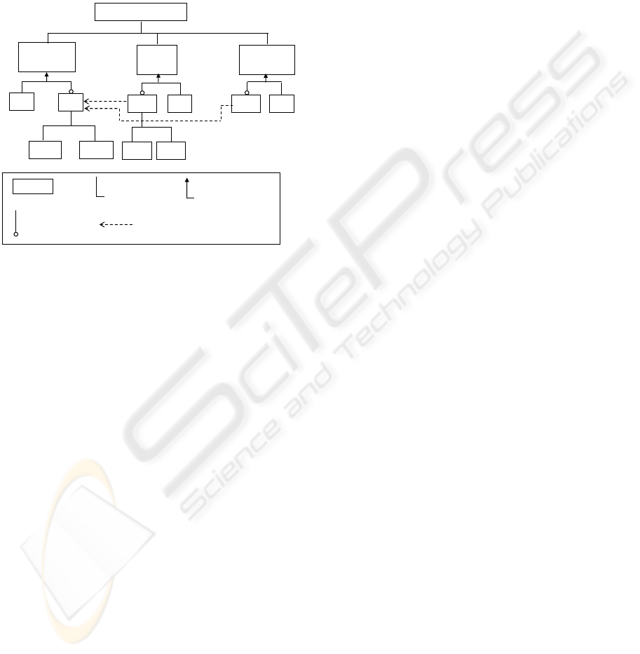
E-CardProduction
Electronic
production
PC
PC
e
PC
p
DF
Database
storing
com position
optionalfeature
aFeature
dependency
DB
p
DF
e
DF
p
DF
p
AC
orspecialization
Defect
control
DB
Figure 1: Traditional feature tree.
Figure 1 presents the functional features of the sys-
tem in the form of a traditional feature tree (Griss
et al., 1998; Svahnberg et al., 2002; van Gurp, 2003).
A traditional feature tree allows for representing com-
positions of features, specialization (inheritance) rela-
tions on features as well as mutual dependencies be-
tween features. In common case xor (not used in our
example) and or specializations as well as optional
features (both shown in Figure 1) allow designers to
configure end-products differently providing variabil-
ity of the system design.
The use of relations between features depends on
the behavioral specification of an end-product. In
particular, this means that the order in which fea-
tures are implemented is also important. Obvi-
ously the correct order of high level features should
be Electronic production, Def ect control and
D atabase storing (Figure 1). However, for the spe-
cialized features it is not so obvious. For example,
features-inheritors AC, DF, DB, PC
p
, DF
p
, etc. in
different configurations may have very different or-
dering relations, and this is not visible in the tradi-
tional feature tree.
Clarifying ordering relations of features at this ab-
stract level of system presentation can prevent mis-
takes in specification and implementation. In practice
such relations are established by use cases (Cockburn,
1997) specifying allowed sequences. Sometimes the
sequences are incomplete. In the next section we
demonstrate by example that such form of clarifica-
tion of feature ordering leaves room for mistakes.
2.1 Formalizing Requirements for
the Systems Producing
Anonymous and Personalized
E-cards
Requirements are usually specified textually (Muller,
2004). Requirements engineers can use the names of
features from the feature tree and manipulate them as
blocks to derive sequences from the text and present
them as use cases (Cockburn, 2000), UML sequence
diagrams (Cockburn, 1997) or sequential processes
in the process algebra notation (Baeten and Wei-
jland, 1990) or as property-formulas in the linear
logic (Felty and Namijoshi, 2003; Berard et al., 2001).
Now, let us imagine that one of our customers
needs to produce anonymous cards, and another one -
personalized cards.
The requirements of the customer who needs
anonymous cards are the following:
1.1. A produced card is either registered in the
database or separated as defective. The allowed se-
quences for the system producing anonymous cards
are: AC · DB and AC · DF . (The names of features
are taken from Figure 1).
1.2. The information about defective cards should not
appear in the database. The requirement is informal.
The requirements of the customer who needs to
produce personalized cards are the following:
2.1. The system for production of personalized e-
cards is supposed to reuse the system for production
of anonymous cards. The requirement is informal.
2.2. The personalized e-card is produced from an
anonymous one by writing into the card additional
electronic personal data (sub-feature PC
e
). After that
the personal data is printed onto the card surface (sub-
feature PC
p
). So the incomplete allowed order is:
AC · ... · PC
e
· ... · PC
p
.
2.3. Information about correctly produced personal-
ized e-cards should appear in the database. The re-
quirement is informal and can be understood differ-
ently. One understanding is that sequence AC · PC
e
·
DB
p
· PC
p
is allowed. Another understanding is that
sequence AC · PC
e
· PC
p
· DB
p
should be imple-
mented.
2.4. Defective cards are separated during production,
so the allowed sequences are AC · DF ; AC · PC
e
·
DF
e
; and AC · PC
e
· PC
p
· DF
p
.
In practice the requirements for both systems can
be presented by use cases. Each use case is unfolded
into a use case scenario (Cockburn, 2000). An exam-
ple of a use case scenario for production of an anony-
mous card is shown in Figure 2.
ICEIS 2006 - INFORMATION SYSTEMS ANALYSIS AND SPECIFICATION
120

Figure 2: Use case scenario.
The descriptions of requirements given above are
the descriptions of the system features-requirements
at the highest level. Presentation of the requirements
as sequences is a necessary step in communication
with customers. However, the set of sequences, pre-
sented, e.g., by use case scenarios, does not give a
complete view on the system behavior because the se-
quences can be inconsistent in the sense that required
sequences joined together can still produce forbid-
den behavior or even contain features unspecified in
the feature tree of the system. So, the requirements
should be checked on consistency.
Moreover, some requirements, for example, 1.2
(about forbidden sequences) and 2.1 (about reuse) are
informal. What should be reused from the system pro-
ducing anonymous cards? We can think of reusing
separate features, sequences of features or the com-
plete behavior of the first system. Another important
question is: what may be reused without violation of
the other requirements? Next section presents an ap-
proach to consistency checking of requirements and
to formalizing the notion of reuse.
3 AN APPROACH TO
CONSISTENCY CHECKING OF
REQUIREMENTS AND
FORMALIZING THE NOTION
OF REUSE
Although the requirements are often incomplete, any
attempt to build from them a picture of complete sys-
tem behavior can be considered as a basis for con-
sistency checking, for completing some incomplete
requirements, for formalizing informal requirements
and for retrieving new ones.
We suggest building a feature computation tree
from allowed sequences which represents dynamics
of the system in an abstract way. The feature com-
putation tree built from features collected by the tra-
ditional feature tree can be further used to validate
consistency of requirements and absence of forbidden
features.
If an inconsistency is found during analysis of a
feature computation tree, then the requirements are
revised or new possible sequences are added to the
tree. Some forbidden sequences can be generated
from the feature computation tree to let a designer to
make a decision if those sequences are really forbid-
den or missing in the set of requirements. As we will
show later, the feature computation tree model also
clarifies the requirement for desired reuse.
3.1 Feature Computation Tree
A feature computation tree is an abstract variant of a
process tree (Baeten and Weijland, 1990), in which
actions are replaces by functional features.
A feature computation tree G
p
=(A, N, E) is a
graph which has a unique path from the node root
to every other node. The root has no input edges.
• A is a set of functional features.
The set of features of a system producing anony-
mous e-cards is A = AC, DF, DB.
• N is a set of nodes, represented by points.
A node n ∈ N of the tree represents an abstract
state of a system under design. A node marks a
starting and/or finishing points of a process imple-
menting a feature. The root represents the initial
state.
• E is a set of arcs.
An arc e =(n
,n”,a) ∈ E of the tree is labelled
by a feature name a ∈ A. An arc labelled by a
stands for a complete process implementing feature
a. Process a can be of different level of complexity,
however, it always has a starting point represented
on the feature computation tree by node n
. The
process can have several outputs, however, all of
them can have an arc connecting each of them to
an abstract final state of the process. Such a final
state is represented on the feature computation tree
by node n”. The final nodes has no output edges.
For example, in Figure 3, arc AC stands for the
process ”Production of an anonymous e-card”, DF -
for the process ”Separation of defective cards”, and
DB represents the process ”Registration of an anony-
mous card in the database”.
Thus, a path in a feature com-
putation tree is a sequence of arcs
((n
1
,n
2
,a
1
), (n
2
,n
3
,a
2
), ..., (n
m−1
,n
m
,a
m−1
)).
There is a unique sequence of features that corre-
sponds to each path: a
1
,a
2
, ..., a
m−1
. A path which
starts from the root is called a root path.
If the designed behavior is cyclic, then a cycle is
represented by two paths: one path for the cycle’s
body and the other path for the cycle’s exit. Repeated
cycle’s bodies are replaced by dots: ”...”. An
infinite sequence of features can be represented by its
repetition rule, e.g. ”abaabb . . . ”, allowing control
over the progress of the repetitions.
A FEATURE COMPUTATION TREE MODEL TO SPECIFY REQUIREMENTS AND REUSE
121

3.2 Feature Computation Trees for
the Systems Producing
Anonymous and Personalized
E-cards
The high-level feature computation tree of the system
for production of anonymous e-cards is shown in Fig-
ure 3. This tree combines two specified sequences
1.1.AC· DF and 1.2.AC· DB in such a way that, if
the features in sequences are the same from the root,
then they are merged. The algorithms of such merg-
ing is described in (Roubtsova and Kuiper, 2002).
As we can recognize in Figure 3, an anonymous
e-card is successfully produced if its informational
image is saved in the database of the system (pro-
cess DB is finished). Otherwise, if a defective e-
card is produced, then the card is separated and the
information about this card should not be kept in the
database (process DF is finished). So, from this tree
we can derive two forbidden sequences DF · DB and
DB · DF and formalize the requirement 1.2, which
says that the information about defective card should
not be saved in the database. We deliberately over-
simplified the picture, but even based on this picture,
we have refined the initial requirements.
Building a feature computation tree from the se-
quences defined in the requirement 2.4 for the system
producing personalized cards we get the feature com-
putation tree shown in Figure 4a on the left hand side.
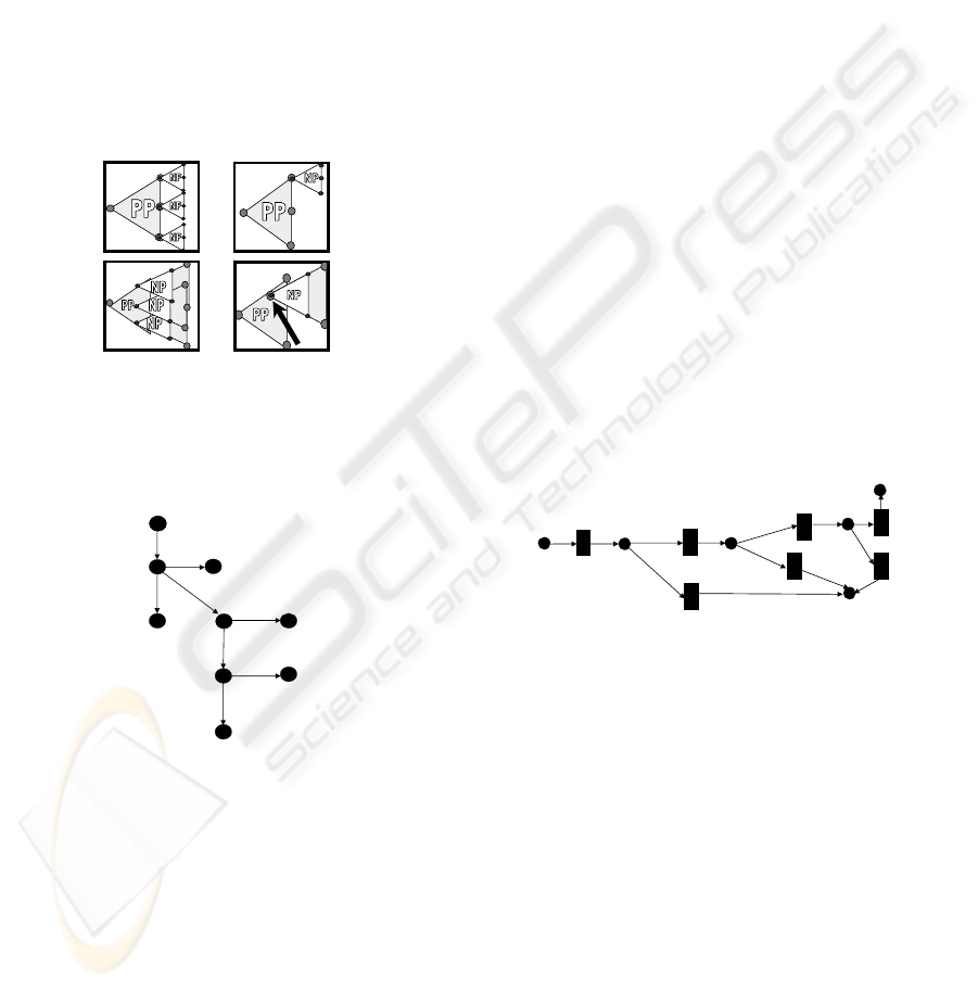
DF
AC
root
DB
Figure 3: The feature computational tree for a system pro-
ducing anonymous e-cards.
In order to prove that a sequence is consistent with
a feature computation tree, we can use the method for-
mally presented in (Roubtsova and Roubtsov, 2003).
The method derives a computation tree from another
computation tree using hiding and blocking tech-
niques defined in process algebra (Baeten and Wei-
jland, 1990). To prove that a sequence is consis-
tent with a computation tree, it is required to find a
path implementing this sequence on the tree. During
derivation of the specific sequence the features start-
ing other paths are blocked. Any sequence started by
the blocked action is cut down. The features that do
not belong to the specific sequence, but situated on
the chosen path, are made invisible (hidden). Hidden
features allow continuing the sequence of the chosen
PC
e
G
PC
p
G
AC
G
PC
e
DF
e
PC
p
DF
AC
DF
p
a
PC
e
DF
e
DB
p
PC
p
DF
AC
DF
p
PC
e
DF
e
DB
p
PC
p
DF
AC
DF
p
cb
Figure 4: Feature computation trees for a system producing
personalized e-cards.
path.
For example, in order to prove that the production
sequence AC · ...· PC
e
· ...· PC
p
(requirement 2.2) for
the feature computation tree is presented in Figure 4a,
we block features DF, DF
e
,DF
p
and have as the re-
sult the sequence AC · PC
e
· PC
p
that matches with
the production sequence (Figure 4a, right hand side).
Two versions of the feature computationtree shown
in Figures 4b and 4c comply with the requirement
2.3 (regarding registration of correct cards in the
database). This is a signal to a requirement engineer
to choose one of them.
In order to make this choice, the forbidden se-
quences should be discovered by means of building
all possible sequences of features from the feature
computation tree and the textual requirements. For
example, sequences AC · DB and AC ·PC
e
·DB
p
are
not allowed because they save the information about
incompletely produced and not printed cards. Se-
quences AC·DF·DB , AC·PC
e
·PC
p
·DF
p
·DB
p
are
not allowed because they save the information about
defective cards.
The forbidden sequence AC · PC
e
· DB
p
is imple-
mented by the computation tree 4c. It can be proven
using the hiding and blocking technique. So, the
feature computation tree (Figure 4b) with sequence
AC · PC
e
· PC
p
· DB
p
is accepted as the correct one
for the system producing personalized cards.
ICEIS 2006 - INFORMATION SYSTEMS ANALYSIS AND SPECIFICATION
122
3.3 Formalizing the Requirement for
Reuse
Now, the requirement 2.1 about reuse needs to be for-
malized.
The feature computation tree allows building some
patterns of reuse.
The patterns of reuse manipulating feature compu-
tation trees are shown in Figure 5. Pattern (1) means
extending all paths of a reused tree by a new tree. Pat-
tern (2) presents extending one path of a reused tree
by a new tree. Pattern (3) means inserting a new tree
into all paths of a reused one. Pattern (4) implies in-
serting a new tree after a specific feature that appears
in a reused tree.
1
2
3
4
Figure 5: Reuse patterns. Feature computation trees are
visualized as triangles with labels PP and NP. PP stands
for a reused process and NP - for a new process.
PC
e
DF
e
DB
p
PC
p
DF
AC
DB
DF
p
Figure 6: Feature computation tree for a system producing
both types of e-cards. Case of incorrect reuse.
Building a system producing personalized cards we
can insert a new feature computationtree after the fea-
ture AC of the computation tree of the system produc-
ing anonymous cards (Figure 6). The resultant tree of
such a design decision will include the forbidden se-
quence AC · DB identified in the previous subsection
3.2. So, we conclude that such complete reuse is in-
correct. The only one path AC ∗ DF of the system
producing anonymous cards can be reused. In order
to produce a personalized card after the feature AC
only the feature PC
e
should be started.
Since the system for production of anonymous
cards cannot distinguish the type of the card, a new
feature computation tree that gives the type of the
card should be built at the beginning of the process
and one path of this tree should be extended by the
feature computation tree shown in Figure 3 and the
other - by the feature computation tree shown in Fig-
ure 4b. In other words, different feature computation
trees and therefore systems should be built for pro-
duction of cards of different types and for production
of cards of both types.
3.4 A Feature Computation Tree
Model as an Internal Model for
Other Models
The features can be ordered using other popular spec-
ification notations like sequence diagrams (OMG,
2003), state charts (Harel and Kupferman, 2002) or
Petri Nets (Murata, 1989; Kindler and Vesper, 1998).
The two latter notations can combine sequences of
features together. An example of the Petri Net model
is shown in Figure 7. Building the Petri Net of the
system we have assumed that transitions (boxes) are
labelled by the names of features and places (cycles)
represent the beginning and end states of processes
implementing features.
AC
PC
e
PC
p
DF
e
DF
DB
p
DF
e
Figure 7: Petri Net for the system producing personalized
e-cards.
When it comes to consistency checks using for-
mal model checking algorithms, all the models like
state charts and Petri Nets are transformed into an
internal computation tree model called in Petri Nets
theory (Reisig, 1985) a reachability graph. At the
feature-based level of abstraction this model is essen-
tially a feature computation tree. So, introducing this
model at the very beginning, we are able to use it as
a basis for logic of reasoning, automated consistency
checks and constructive notion of reuse.
That is why we suggest using the feature computa-
tion tree model for the requirement engineering. Be-
sides, the feature computation model could be de-
rived from any model used by the designer, it allows
him/her to formalize and validate consistency of re-
quirements at a high level of abstraction.
A FEATURE COMPUTATION TREE MODEL TO SPECIFY REQUIREMENTS AND REUSE
123

4 TOOL SUPPORT
In the area of requirements engineering there are three
points of particular attention that are not covered by
modern tools.
Firstly, the process of formalizing requirements is
not covered by modern specification tools (Geppert
and Schmid, 2002). Although there are tools that
support proving formally written logical expressions
(theorem provers) (Clarke et al., 1999; Berard et al.,
2001), the step of getting logical expressions from in-
formal requirements is not yet implemented.
Secondly, the precise design notations are weakly
linked to the variety of requirements specification
techniques, which makes it difficult to trace require-
ments within designs.
Thirdly, so far there was no support for specifica-
tion of reuse goals.
We have made a tool-prototype that addresses all
tree above mentioned issues.
1. The tool helps to formalize requirements as func-
tional features and to specify desired or/and forbid-
den output related to the specified features.
The tool provides a list of available functional fea-
tures derived from the system’s feature tree. This
list can be used by the requirements engineer to
represent requirements as sequences.
The tool is able to build feature computation tree
from given sequences and to check their consis-
tency. Using the feature computation tree the set of
statements about impossible outputs of the system
is formulated and presented to the requirements en-
gineer for control.
2. Designers of a system may traditionally use differ-
ent standard notations. These notations should be
related to the requirements. It has to be possible to
trace them back to the requirements. As a large va-
riety of specification notations can be transformed
to our computation tree model, there is always a
possibility to make such a transformation with tool
support and to validate the results by the require-
ments. At the moment we have implemented sup-
port for transformation of a set of sequence dia-
grams to a feature computation tree.
3. We have proposed a taxonomy of reuse goals on the
basis of a logic of reuse (Roubtsova and Roubtsov,
2004). The logic of reuse is aimed to express re-
lations between the part of the system which is
reused and the new part. The reused part is ei-
ther a sequence or a subtree. The joining points
are the nodes of the tree. Each node represents the
end point of a successfully fulfilled feature func-
tionality. The reuse relations are numerous but the
types of computation tree logic formulas represent-
ing them are classified. In the tool, we use visual
images of reuse patterns, like the ones shown in
Figure 5. Choosing an image designer automati-
cally gets the formal expression of the reuse goal
and the corresponding procedure for correctness
checks.
5 RELATED WORK AND
CONCLUSION
To reduce the cost for and time spent on implementa-
tion, the possible conflicts of requirements should be
found at the stage of requirements engineering.
The group of feature interaction detection ap-
proaches (Felty and Namijoshi, 2003; Cheng and
Ohta, 1995) presents features by linear temporal logic
formulas and checks their possible conflicts pair by
pair. If a new requirement is added to the set of n
requirements then n pairwise checks of requirements
should be fulfilled. The feature interaction detec-
tion approaches do not create a general view on the
designed system and do not formalize the notion of
reuse suitable for the case.
The group of process-oriented approaches (Basten
and van der Aalst, 2001; Wehrheim, 2002) do not
relate modelling to requirements and do not formu-
late the desired reuse. This makes it difficult to use
process-oriented approaches at the stage of require-
ments engineering and to validate consistency of re-
quirements. This group of approaches uses an exis-
tential definition of reuse. It means that the process
models of an old and a new system are produced and
the old one should be derivable from the new one by
hiding and blocking new actions in the new process
model. This definition of reuse claims that if some
sequence of hiding and blocking operations, such that
allows deriving the old system can be found, then the
new system reuses the old one. The existential ap-
proach can cause mistakes, because, in general, dif-
ferent sequences of hiding and blocking operations
may allow deriving the old system, and the proven
reuse may not correspond to the desired reuse. The
process-oriented approaches do not answer the ques-
tion as to how to apply hiding and blocking operations
in order to prove the desired reuse.
We have defined a feature computation tree model
to complement the traditional feature tree model. This
makes it easier to formulate requirements in terms of
sequences of features and to automate building a fea-
ture computation tree from such requirements. This
prevents appearance of features that are unspecified
in the feature tree. Due to the lack of room we have
not formally defined the relation between the feature
tree and the feature computation tree in the paper: it
is a subject of another work.
The feature computation tree model supports the
ICEIS 2006 - INFORMATION SYSTEMS ANALYSIS AND SPECIFICATION
124

level of abstraction that is sufficient for requirements
engineering. It generates an image of the system be-
havior, supports consistency checks of requirements
and stimulates specification of forbidden sequences
and other constraints. One class of such constraints
is the class of reuse constraints. The combination of
the feature computation tree model and the logic of
reuse provides flexibility in the specification of reuse.
Different reuse possibilities become clear and can be
formalized with the help of the feature computation
tree model. Moreover, with the help of the tree, the
impossible reuse can be found.
We have applied our method so far for resolving
conflicts of requirements and configurations at the im-
plementation and testing stages of complex systems
development. By means of this paper we would like
to show how beneficial it would be to apply the ap-
proach at the stage of configuration specification or
specification of system extensions.
ACKNOWLEDGMENTS
The authors thank Prof. Jan Friso Groote from the
Technical University Eindhoven, Prof. Mehmet Ak-
sit, Dr. Arend Rensink and TRESE research group
from the University of Twente and also Dr. Gerrit
Muller from the Embedded Systems Institute (Eind-
hoven) for useful discussions of the paper.
REFERENCES
Baeten, J. and Weijland, W. (1990). Process Algebra. Cam-
bridge University Press.
Basten, T. and van der Aalst, W. (2001). Inheritance of
behaviour. The Journal of Logic and Algebraic Pro-
gramming, 46:47–145.
Berard, B., Bidoit, M., Finkel, A., F.Laroussinie, Petit, A.,
Petrussi, L., Schnoebelen, P., and McKezie, P. (2001).
Systems and Software Verification. Model-Checking
Techniques and Tools. Springer-Verlag.
Cheng, K. and Ohta, T., editors (1995). Feature Interactions
in Telecommunications III, October 11-13, 1995, Ky-
oto, Japan. IOS Press.
Clarke, E., Grumberg, O., and Peled, D. (1999). Model
Checking. MIT Press, Cambridge, MA.
Cockburn, A. (1997). Structuring Use Cases with Goals.
Journal of Object-Oriented Programming Sep-Oct
and Nov-Dec.
Cockburn, A. (2000). Writing Effective Use Cases.
Addison-Wesley.
DATACARD (2005). DATACARD 9000 Series
System. Retrieved October 20, 2005 from
http://www.identisys.com/documents.
Douglass, B. (2003). UML 2.0: Incremental Im-
provements for Scalability and Architecture.
www.rtcmagazine.com/pdfs/2003/04/.
Felty, A. and Namijoshi, K. (2003). Feature Specification
and Automated Conflict Detection. ACMTransactions
on Software Engineering and Mothodology, 12(1):3–
27 .
Geppert, B. and Schmid, K. (2002). Requirements Engi-
neering for Product Lines. -An Overview- . In Inter-
national Workshop on Requirements Engineering for
Product Lines, REPL’02, pages 1–4, Essen, Germany.
Griss, M., Favaro, J., and d’Alessandro, M. (1998). In-
tegrating feature modeling with the RSEB. In Fifth
International Conference on Software Reuse (Cat.
No.98TB100203), pages 76–85, Los Alamitos, CA,
USA. IEEE Comput. Soc.
Harel, D. and Kupferman, O. (2002). On Object Systems
and Behavioural Inheritance. IEEE Transactions On
Software Engireering, 28(9):889–903.
Kindler, E. and Vesper, T. (1998). ESTL:A Temporal Logic
for Events and States. In: Desel, J.; Silva LNCS 1420,
ICATPN’98, pages 365–384.
Muller, G. (2004). CAFCR:AMulti-view Method for Em-
bedded Systems Architecting:Balancing Genericity
and Specificity. Technical University Enidhoven.
Murata, T. (1989). Petri Nets: Properties, Analysis and Ap-
plications . Proceedings of the IEEE, 77(4):541–580.
OMG (2003). UML 2.0 specification. Retrieved October
20, 2005 from http://www.omg.org/uml/.
Reisig, W. (1985). Petri Nets. An Introduction. Springer-
Verlag.
Roubtsova, E. and Kuiper, R. (2002). Process semantics for
UML component specifications to assess inheritance.
ENTCS V 72(3), Editors P.Bottoni, M. Minas.
Roubtsova, E. and Roubtsov, S. (2003). UML-based Tool
for Constructing Component Systems via Component
Behaviour Inheritance. ENTCS V.80, Editors T.Erts,
W. Fokkink.
Roubtsova, E. and Roubtsov, S. (2004). Constraints of Be-
havioural Inheritance . Springer LNCS 3047, Editors:
Flavio Oquendo, Brian Warboys, pages 115–134.
Svahnberg, M., van Gurp, J., and Bosch, J. ( 2002). A Tax-
onomy of Variability Realization Techniques. Tech-
nical paper ISSN: 1103-1581, Blekinge Institute of
Technology, Sweden.
van Gurp, J. (2003). On the Design and Presentation
of Software Systems. Rijksuniversiteit Groningen,
Groningen.
Wehrheim, H. (2002). Checking behavioural subtypes via
refinement. In B. Jacobs and A. Rensink, editors,
FMOODS 2002: Formal Methods for Open Object-
Based Distributed Systems, pages 79–93.
A FEATURE COMPUTATION TREE MODEL TO SPECIFY REQUIREMENTS AND REUSE
125
