
RECOVERY SERVICES FOR THE PLANNING
LAYER OF AGENTS
Khaled Nagi, George Beskales
Computer and Systems Engineering Department,Faculty of Engineering, Alexandria University, Egypt.
Keywords: Software agents, planning layer, recovery services, agent robustness, agent simulation.
Abstract: Software agents represent aim at automating user tasks. A central task of an agent is planning to achieve its
goals. Unexpected disturbances occurring in the agent execution environment represent a serious challenge
for agent planning. In this work, a recovery model for the planning process of agents is proposed to cope
with disturbances caused by system failures; which often lead to system crashes. The proposed recovery
model supports the Hierarchical Task Networks (HTN) planners which represent a broad family of planners
that are widely used in agent systems. A prototype for the proposed recovery services is implemented to
demonstrate the feasibility of the proposed approach. Furthermore, a simulation is built and many simulation
experiments were conducted to gain insight about the performance of the proposed recovery model.
1 INTRODUCTION
Software agent systems are introduced to ease auto-
matable tasks of the end user. One of the important
features that are required to exist in the developed
agents is robustness. Relying on agents to perform
critical tasks necessitates that they possess a high
level of reliability to overcome possible failures in
any of the agent components or in its environment.
Various agent architectures tend to group agent
components into subsystems, i.e. layers. Typical
layers found in existing agent systems can be classi-
fied into the following:
Cooperation Layer: this layer is responsible for
the social ability of the agent. Interaction and com-
munication with other agents in the environment are
handled by this layer in order to allow goal sharing
and plan execution sharing.
Planning Layer: having set a goal to achieve, the
agent begins to generate a plan -which can be con-
sidered as a set of actions- to reach that goal. The
agent accepts the current state of the environment,
the goal to achieve and the possible actions allowed
in the environment. The agent then attempts to gen-
erate a plan that accomplishes these goals.
Execution Layer: This layer is responsible for
executing the planned actions in the agent environ-
ment. This layer is also responsible for scheduling
the tasks for execution to avoid invalid tasks inter-
leaving. Execution layer may include interface com-
ponents that are required to submit the agent actions
to the environment, e.g. database interfaces
.
1.1 Robustness of Agents
Robustness of agents has long been considered by
agent system developers to provide a reliable execu-
tion of agents. A robust agent can be defined as an
agent that is capable to identify and overcome a fi-
nite set of failures in order to allow transparent con-
tinuation of agent operation.
Robustness should cover all layers of the agent to
handle all possible failures/disturbances at each
layer. Most of previous work in this context concen-
trated on the cooperation layer and the execution
layer. Our recovery model addresses the planning
layer to handle disturbances due to system failures;
either hardware or software. Typical types of distur-
bances are the crash of the agent, and hence the loss
of its generated plans, or unplanned changes of the
state of the agent environment, which may make the
generated plan invalid. We assume the correctness
of the planning algorithms and hence the validity of
the generated tasks. Therefore, our solution does not
handle crashes due to logical errors in the plan itself.
Naturally, after a disturbance occurs, the agent
has to restart the planning process from scratch if no
recovery services are provided. Recovering of the
generated plan minimizes the penalty of these dis-
turbances by restoring a valid plan and returning it to
the planner.
138
Nagi K. and Beskales G. (2006).
RECOVERY SERVICES FOR THE PLANNING LAYER OF AGENTS.
In Proceedings of the Eighth International Conference on Enterprise Information Systems - SAIC, pages 138-146
DOI: 10.5220/0002443601380146
Copyright
c
SciTePress

2 RECOVERY MODEL
A recovery model is built to provide a robust plan-
ning process of agent systems. A lot of planning
algorithms can be exploited to perform the planning
of the agent goals. One family of these planners is
the Hierarchical Task Networks (HTN) (Erol, et al.,
1994) and (Erol, 1995). The planners under this fam-
ily achieve a plan for a set of goal tasks by decom-
posing them into more primitive tasks. The decom-
position process is repeated until the most primitive
tasks are achieved. There are many implementations
for HTN such as NOAH, NONLIN, MOLGEN,
UMCP, SHOP, SHOP2 (Nau et al., 2003) and oth-
ers. This family of planners is adopted to be sup-
ported by the proposed recovery service to prove the
concept of plan recovery.
2.1 Overview of HTN Planning
HTN planners accept the initial state of the envi-
ronment, the goal tasks, and the definition of the
problem domain as input. The output of the planner
is a plan that can achieve the goal tasks.
Tasks are classified to primitive and non-
primitive tasks. Non-primitive tasks are abstract
tasks that must be decomposed by the planner to a
set of more primitive tasks. Primitive tasks are the
tasks that can be achieved by a single action (opera-
tor).
An environment state S is a set of ground atoms
that are true in the environment. The initial state at
the beginning of planning is denoted as S
0
. An op-
erator
α
is an action that can be executed in the
agent environment. It can be represented by a tuple
(head, parameters, precond, del, add), where head is
the operator name, parameters are its variable pa-
rameters, precond is a list of precondition that must
be true in the environment state before execution of
the operator, del is a list of terms to be removed
from the state after execution, and add is a list of
terms to be added to the state.
Define a function named RESULT that maps a
pair of a state and an operator to another state:
RESULT: S × Op Æ S
A plan P is a set of operators with a dependency
between them. Formally, a plan P= {{(n
1
:
α
1
),…,
(n
k
:
α
k
) },<
p
}, where
α
i
is an operator in the plan with
labels n
i
to distinguish similar operators. Define a
function PL_RESULT that maps an initial state and a
plan to a final state:
PL_RESULT: S × P Æ S.
PL_RESULT applies the operators in plan P succes-
sively in their precedence order against an initial
state S
0
to achieve a final goal state S
g
. A method m
is used to decompose a non-primitive task. A
method m can be defined as follows:
m = (head, parameters, precond, subtasks, <
m
),
where head is the method name, parameters are a
list of method parameters, precond are the precondi-
tions of the method, subtasks are a set tasks that can
accomplish the goal task, and <
m
is the dependency
relation between tasks in subtasks. A problem do-
main D is defined as a tuple (At,Op,Me) , where At is
a list of all possible atoms in this domain, Op is a list
of possible operators and Me is a list of possible
methods. A planning problem Pr= (D,S
0
,T) consists
of a problem domain D, an initial state S
0
and goal
tasks T. Its solution is a plan P that can achieve the
goal tasks.
Generally, an HTN planner, e.g. SHOP2, repeat-
edly picks (and removes) some task from T, decom-
poses it to more primitive tasks and returns them to
T until the most primitive tasks remain in T. At this
point, each primitive task can be achieved by a sin-
gle operator. The operators used are appended to the
output plan and the plan is then returned to the exe-
cution layer after all tasks are achieved.
2.2 Assumptions
We assume that the agent environment is open, i.e. it
can be modified by other external entities, and his-
tory-independent, i.e. the outcome of an operator
does not depend on the previously executed opera-
tors. Also, it is assumed that the execution process of
the agent checks the satisfaction of all operator pre-
conditions before executing.
Plan execution can begin before the completion
of its generation. In other words, generated tasks of a
partially developed plan can be executed by the
agent. This feature is especially important in agent
systems where planning can take considerable time,
which motivates the necessity of recovery. Some
planners cannot allow early execution of plans for
certain reasons such as the use of backtracking algo-
rithms where a generated task be removed at a late
planning step. We adopt the more general case
where early execution of partially developed plans is
allowed.
2.3 Architecture of the Proposed
Recovery Model
Figure 1 depicts the architecture of the proposed
recovery model. A typical agent system is used as a
basis for the recovery service. The agent system
consists of three typical layers: Execution Process,
Planner, and Cooperation Process. The plan recov-
RECOVERY SERVICES FOR THE PLANNING LAYER OF AGENTS
139
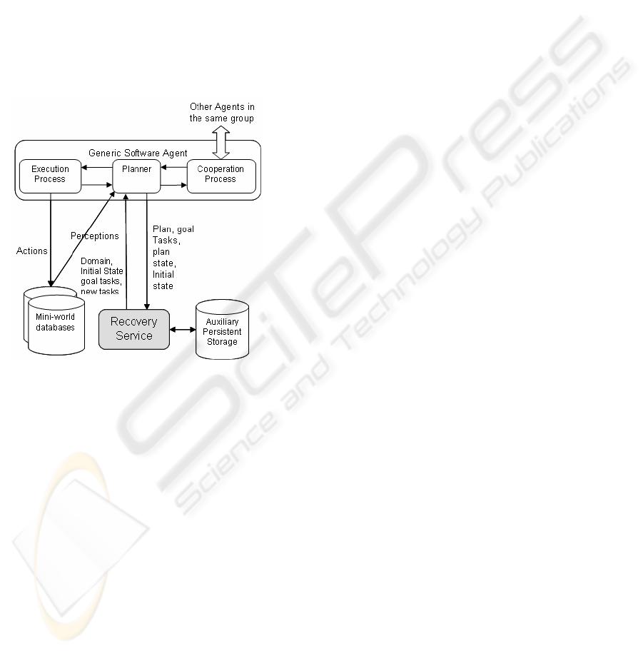
ery service is tightly coupled with the planning
process to provide recoverable plans. The planner
initially submits the planning problem which is rep-
resented by the tuple (D,S
0
,T). Every time the plan-
ner generates a new task, it has to submit it to the
recovery service so that the persistent image of the
plan can be updated. Through its interaction with the
execution process, the planner communicates the
schedule and the state of execution of the plan to the
recovery service module. Upon disturbance, the re-
covery service module recovers a valid plan with
respect to the new environment state and returns it to
the planner so that it can continue planning. The
recovery service uses a persistent storage unit to
store an image of the submitted planning informa-
tion so that it can be retrieved after a crash occurs.
Figure 1: Agent system architecture with integration of
planning recovery service.
The traditional data structures used in the HTN
planner, and which are also used in the recovery
module, are the plan P, the goal tasks T, the initial
state S
0
, the planning state S
p
and the problem do-
main D. Additionally, we introduce a new data
structure, the Plan Task List (PTL), to enable suc-
cessful recovery of plans. These data structures rep-
resent the state of the planner at any point of time
and hence they have to be stored and maintained by
the recovery module. The PTL data structure pre-
serves the following:
– tasks hierarchy, i.e. the parent-child relation be-
tween generated tasks,
– operators used to achieve primitive tasks,
– methods used to decompose non-primitive tasks,
– tasks that are already achieved or decomposed
which are discarded from the goal tasks T.
Formally the PTL can be represented as follows:
PTL={(t
i
, subtasks
i
, m
i
, α
i
, θ
i
), <
p
}, 0 ≤ i ≤ no of
nodes in the tasks hierarchy; where subtasks
i
are the
subgoals of t
i
, α
i
is the operator to achieve t
i
, m
i
is
the method used to decompose t
i
to subtasks
i
, and
θ
i
is the used binding that unifies the operator or the
method with the task. Subtasks
i
and m
i
must be equal
to φ whenever t
i
is primitive, and α
i
must be φ if t
i
is
non-primitive. Also, subtasks
i
, m
i
, α
i
and
θ
i
must be
equal to φ if t
i
∈
T because at this point the task t
i
is
not yet achieved by an operator, in case of primitive
task, or decomposed, in case of non-primitive task.
Each task in the goal tasks T is initially copied to
PTL. When a task is decomposed, its subgoals are
associated with it without deleting it from PTL.
In (Beskales, 2005), we prove that this set of data
structures is necessary and sufficient for a correct
recovery of plans according to procedures men-
tioned in the next section.
2.4 Logging and Recovery
Procedures
In order to allow the recovery service to do its func-
tion, logging procedures must be implemented to
record newly generated tasks by the planner and to
update the PTL structure accordingly. These proce-
dures are: Initialize, SubmitPrimitiveTask, Submit-
NonPrimitiveTask and UpdateTaskExecStatus. Due
to space limitation, a pseudo code for each of these
procedures is omitted. They can be found in
(Beskales, 2005). The procedure Initialize must be
invoked at beginning of planning. It stores new
planning problems in the persistent storage and ini-
tializes the PTL structure. The procedures Submit-
PrimitiveTask and SubmitNonPrimitiveTask must be
invoked by the planner after a primitive task is
achieved by an operator and a non-primitive task is
decomposed using a method, respectively. They
store the subtasks and the used method in case of a
non-primitive task, or the used operator in case of a
primitive task. The PTL and P structure are updated
accordingly. All modified structures are updated in
the persistent storage. The procedure Up-
dateTaskExecStatus should be invoked by the execu-
tion process when a task is executed or by the plan-
ner if it has a full knowledge about the execution
status of tasks from the execution process. The pro-
cedure RecoverPlan, listed below, is invoked by the
planner after occurrence of disturbances. It retrieves
the stored planning data from the persistent storage
and starts to evaluate the validity of each item with
respect to the current environment state. Only valid
plan operators are returned in the plan while invali-
dated tasks are removed from the plan and are added
ICEIS 2006 - SOFTWARE AGENTS AND INTERNET COMPUTING
140
to the goal tasks for replanning. The returned data
represents a consistent state for the planner, from
which it continues processing.
recoverPlan(State S
c
): P, T, S
0
, S
p
{
/*invoked after a disturbance. New en-
vironment state is S
c
*/
if(crash occurred)
restore(D,P,T,PTL,S
0
,S
p
);
S
c
'=S
0
; // S
c
' is the supposed state
iterate over t
∈
P in prec. order <
p
{
if(t.execStatus = 'completed'){
S
c
'= RESULT(S
c
', t.α);
removeTask t from PTL and P;
}
}
S
0
=S
c
; //update S
0
to the current env.
state
if(S
c
==S
c
'){
return P,T,S
0
,S
p
;
}else { //S
c
≠S
c
'
S
p
=S
c
;
iterate over t
∈
PTL in depth first
traversing in precedence order (<
p
){
if((t == primitive
∧
t.α.precond
is not satisfied by S
p
)
∨
(t is
not primitive
∧
t.m.precond is
not satisfied by S
p
)){
Task[] SubTasks =
φ
;
Task[] Dependents = {t};
Loop until SubTasks and Dependents
stabilize{
SubTasks = SubTasks
∪
{t'
∈
PTL: ancestor(t'',t')
∧
t''
∈
Dependents
∪
SubTasks};
Dependents = Dependents
∪
{t'
∈
PTL: t'' <
p
t'
∧
t''
∈
SubTasks
∪
Dependents};
}
Dependents = Dependents–SubTasks;
For each task t
s
∈
SubTasks{
PTL.removeTask(t
s
);
T.removeTask(t
s
);
PTL.removeBinding(t
s
.
θ
);
T.removeBinding(t
s
.
θ
);
if(t
s
is primitive
∧
t
s
∈
P)
P.removeTask(t
s
);
}
For each task t
p
∈
Dependents{
PTL.removeBinding(t
p
.
θ
);
T.removeBinding(t
p
.
θ
):
T.addTask(t
p
);
Task t'=PLT.searchForTask(t
p
)
t'.operator = t'.method =
t'.bindings = t'.subtasks =
φ
;
if(t
p
is primitive
∧
t
p
∈
P)
P.removeTask(t
p
);
}
}else // t.precond is satisfied by S
p
S
p
= RESULT(S
p
,t.α);
}
}
update (P,T,PTL,S
0
,S
p
);
return P,T,S
0
,S
p
;
An example of plan recovery is shown in Figure
2. After generating a plan P=(t
0
, t
1
, t
2
, t
3
, t
4
) with
remaining goal tasks T={t
5
,t
6
,…}, and assuming that
t
0
and t
1
are executed, a disturbance occurs. Invoca-
tion of the recovery procedure will result in the fol-
lowing:
– Removing all completed tasks, i.e. t
0
and t
1
.
– Traversing the non-completed tasks in P and
checking their validity with respect to the new
environment state. This results in removing inva-
lid tasks t
4
.
– Removed tasks are added to the goal tasks T to
be replanned.
– Finally, new initial state S
0
(which equals the
current environment state S
c
) and new planning
state S
p
are calculated and returned to the planner
along with the modified P and T.
Figure 2: An example of plan recovery.
RECOVERY SERVICES FOR THE PLANNING LAYER OF AGENTS
141
3 SIMULATION MODEL
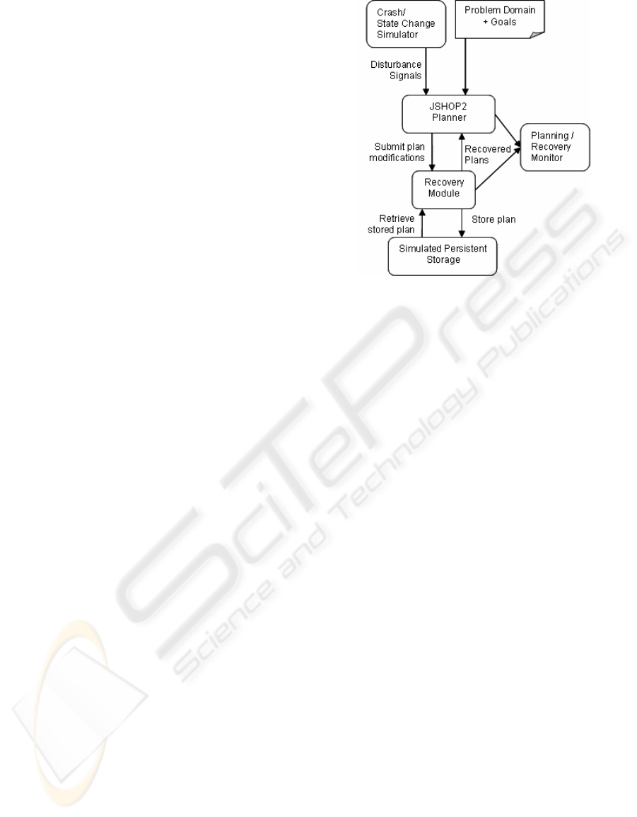
3.1 The Prototype
In order to verify the feasibility of the proposed re-
covery model, a prototype is built that utilizes the
logging and recovery procedures described earlier.
The modules of the prototype, illustrated in Figure 3,
are described below.
We chose the JSHOP2 planner (Ilghami) to be
integrated with our recovery service. JSHOP2 is an
open-source Java implementation for the SHOP2
planner, which takes the problem domain and goals
as input parameters. The Recovery Module is re-
sponsible for storing and recovering the generated
plans. It mainly consists of the implementation of
the logging procedures and recovery procedure; de-
scribed in Section 2.4. The Simulated Persistent
Storage is a transient data structure used to keep an
image of the recovery information submitted by the
recovery service. In our simulated environment,
there is no need to actually store the plan in a physi-
cal persistent storage because the crashes are simu-
lated by another module rather than actually per-
formed. Upon receiving a crash signal, the planner
internal variables are nullified, the recovery proce-
dure retrieves the stored recovery information from
the simulated persistent storage, and finally a valid
plan is returned to the planner after removing invalid
tasks. The Crash/State Change Simulator Module is
used to generate disturbances including simulated
crashes of the planner and unplanned changes of the
environment state according to the probability dis-
tributions mentioned in Section 3.2. The Plan-
ning/Recovery Monitor is responsible for observing
the output of the planner as well as the recovered
plans returned by the recovery service after a distur-
bance. By observing system outputs, the user can
validate the correctness of the planner and the re-
covery service and gather the necessary measure-
ments for the performance metrics described in Sec-
tion 3.3.
Figure 3: The implemented prototype.
3.2 Probability Distributions Used in
the Simulation
The inter-arrival time between disturbances (in
terms of processed tasks) follows an exponential
distribution with mean T
dst
. The probability of
change of each ground atom in the environment state
follows a Bernoulli distribution with probability of
modification P
mod
. If a ground atom is selected for
modification, the new atom is randomly selected
from all possible states. The number of completed
operators of the generated plan at time of distur-
bance is uniformly distributed in the range from zero
to the length of the partially generated plan. The
probability of crash occurrence given that a distur-
bance already occurred is assumed to follow a Ber-
noulli distribution with expected probability of crash
occurrence equal to P
cr
.
3.3 Performance Metrics
The following performance metrics are used in the
simulation study:
– The number of processed nodes used in the plan
generation is the main performance metric. In
the presence of recovery, the total number of
processed tasks is calculated including those
processed by the planner and the recovery mod-
ules. The ratio of the number of tasks processed
by the recovery procedure to the number of tasks
processed by the planner is also monitored to
provide an indicator about the relative overhead
of the recovery service with respect to the plan-
ner.
ICEIS 2006 - SOFTWARE AGENTS AND INTERNET COMPUTING
142

– The number of performed I/O operations is also
monitored. To count the I/O operations, the
number of read/written bytes is monitored in
each of the I/O events and then the number of
I/O accesses is calculated at each event by divid-
ing the number of transferred bytes over the
number of bytes per page.
– The storage requirements of recovery are also
recorded to obtain a complete image about the
requirements of the recovery process. The stor-
age requirement is defined as the maximum
number of bytes stored in the persistent storage
for the duration of the planning process.
3.4 Recovery Trade-off
Recovery service introduces new overheads as a
result of logging of planned tasks and executing re-
covery procedure after disturbances. These over-
heads can be justified if the recovery service can
actually assist the planner to retract to a mature plan-
ning state rather that restarting the planning process
from scratch.
The proposed logging procedures and recovery
procedure have the following overhead:
– Fixed I/O overhead: due to logging of planning
events.
– Storage overhead: used to store the logged plan-
ning information.
– Recovery overhead: encountered when recovery
procedure is invoked after occurrence of distur-
bance. It is composed of additional I/O opera-
tions to retrieve the stored image of PTL, T and
P from the persistent storage in case of crash,
and the number of processed tasks in order to
check the validity of each task in PTL before re-
turning the recovered plan and goal tasks to the
planner.
The cost of the planning process consists of:
– Processed tasks: in order to generate a plan for
the goal tasks, i.e. to decompose them using do-
main methods and operators to achieve a plan,
and
– I/O operations: which are performed initially and
after each disturbance to read current environ-
ment state, i.e. perceptions.
For the recovery approach to be efficient, the
sum of the planning cost and logging/recovery costs
must be less that the planning cost in absence of
recovery services. In such case, the source of recov-
ery efficiency is that it allows the planner to retract
to a mature, consistent and valid planner state rather
than reinitializing its state after occurrence of distur-
bances. The number of disturbances must overpass a
specific threshold and the recovered planner state
should be as mature as possible. To find out these
thresholds, several experiments are conducted based
on the prototype under various conditions.
4 EXPERIMENT RESULTS
4.1 Effect of Varying T
dst
and P
mod
As expected, there is a significant performance gain
when the recovery procedure is used especially at
high disturbance rates, i.e. low values of T
dst
, and in
semi-static environments, i.e. at low values of P
mod
(P
mod
= 0.05) as illustrated in Figure 4 and 5. In ab-
sence of recovery services, the planner has to restart
with an empty plan each time after disturbance oc-
currence while the recovery process restarts the
planner from a more mature state. It is normal that
increasing rate of disturbances, i.e. decreasing T
dst
,
leads to increasing the gap between the two ap-
proaches. This is mainly because each additional
disturbance costs the planner further penalty when
the recovery service is disabled compared to the case
where the recovery service is exploited.
In Figure 5, it is noticed that the number of per-
formed I/O operations at high values of T
dst
, is
slightly higher when the recovery service is used. As
T
dst
begins to decrease, the recovery enabled plan-
ning performs better than the traditional approach in
terms of I/O operations. This observation is expected
because at low rate of disturbances, the recovery
service performs a greater number of I/O operations
to log planned tasks, compared to the traditional
approach where I/O operations are only performed
for perceptions. At higher rates of disturbances, the
duration of planning time when recovery services
are disabled is much greater than the duration when
recovery service is used because each disturbance
has much penalty. As a result, the number of distur-
bances in the complete duration of planning is much
greater when no recovery is used. This is directly
reflected on the increasing number of I/O operations
performed to read the environment perceptions after
each disturbance, which exceeds the logging and
recovery I/O overhead.
RECOVERY SERVICES FOR THE PLANNING LAYER OF AGENTS
143
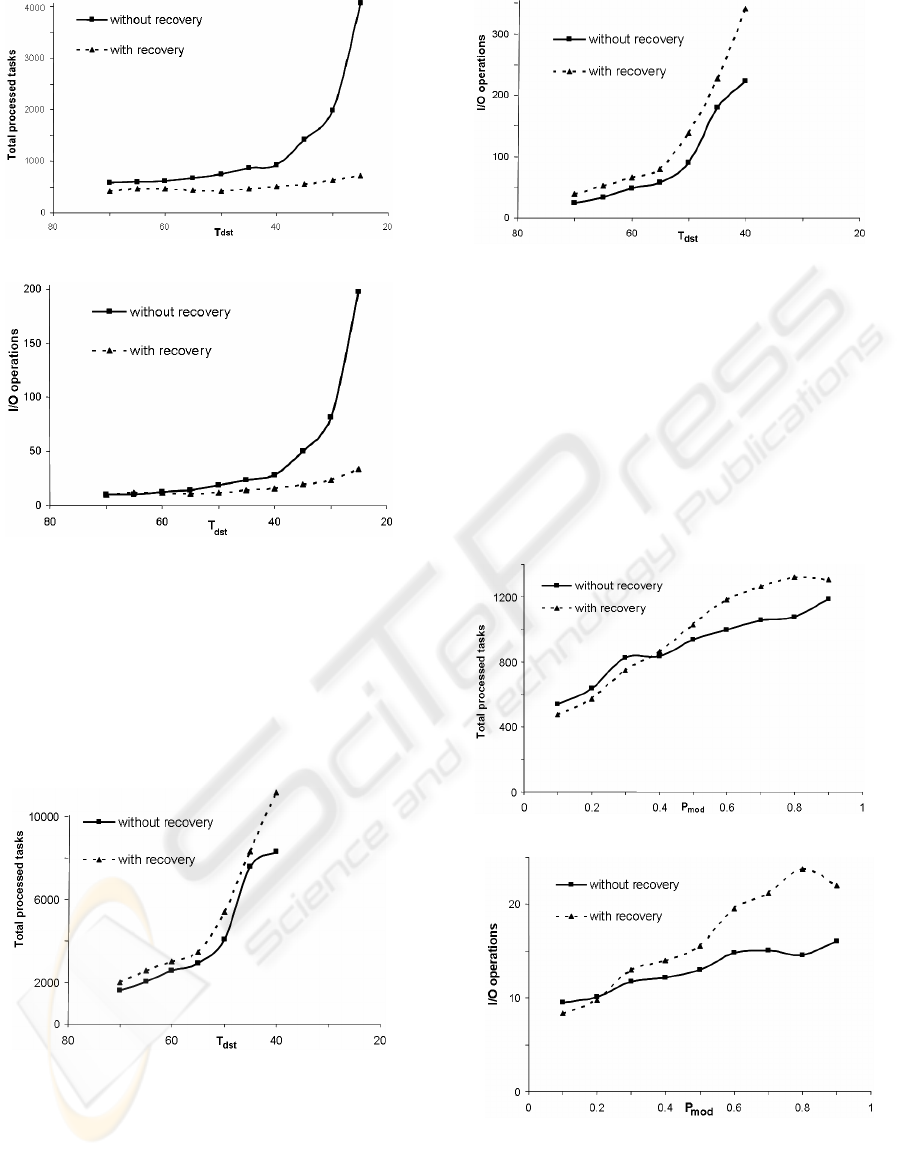
Figure 4: Total processed tasks (P
mod
= 0.05).
Figure 5: Performed I/O operations (P
mod
= 0.05).
Figures 6 and 7 depict the processed tasks and
I/O operations in a highly-dynamic environment
(P
mod
=0.95) where environment state dramatically
changes after disturbances. It is observed that the
recovery service is inefficient at highly dynamic
environments regardless of the rate of disturbances
because the function of recovery procedure is most
likely useless.
Figure 6: Total processed tasks (P
mod
= 0.95).
Figure 7: Performed I/O operations (P
mod
= 0.95).
The main reason is that at very high values of
P
mod
, the recovery service loses its advantage to re-
cover to a mature state of the planner and degenerate
to the same effect of the traditional approach, which
leaves the logging I/Os as an unjustified overhead.
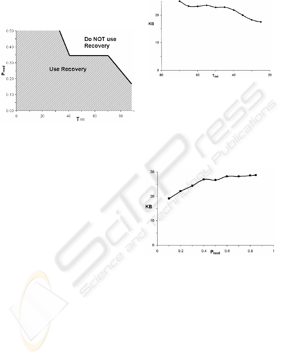
In Figure 8 and 9, we fix T
dst
at 80 and vary P
mod
from 0.1 to 0.9. We observe different breakeven
points than with the previous sets of experiments.
Here the value of P
mod
should not exceed 0.45 in
order to make the recovery enabled approach cost-
effective in terms of both CPU and I/O operations.
Figure 8: Total processed tasks (T
dst
= 80).
Figure 9: Performed I/O operations (T
dst
= 80).
So, we have to find out the constraints for effi-
cient plan recovery. In other words, we have to de-
fine the environment in which the recovery-based
planning supersedes the traditional non-recoverable
planning. In order to determine the thresholds of
ICEIS 2006 - SOFTWARE AGENTS AND INTERNET COMPUTING
144
P
mod
for other values of T
dst
, we executed multiple
experiments for all values of P
mod
and T
dst
. The
threshold values can be found in Figure 10.
Figure 10: Constraints for efficient use of recovery.
The area below the curve contains the values of
T
dst
and P
mod
that make the recovery-based approach
effective. A conservative approach is adopted while
identifying the threshold values so that both the
number of processed tasks and I/O operations of our
approach must be lower than those of the traditional
approach to conclude that the former is more effi-
cient.
Since the absolute value for this threshold line
varies with the problem domain, the simulator used
for analyzing the performance of the proposed ap-
proach, can also be used as a system management
tool that helps system administrators to keep per-
formance requirements. Thresholds for T
dst
and P
mod
can be obtained for the specific problems by the
simulator. Then, the values of T
dst
and P
mod
of the
agent environment can be monitored at the system
operation, and a decision for enabling/disabling the
recovery services can be taken accordingly.
4.2 Storage Requirements
Figure 11 depicts the storage overhead against vary-
ing values of T
dst
in a semi-static environment where
P
mod
=0.05. It is observed that increasing the rate of
disturbances results in less storage requirements.
This is because increasing rate of disturbances re-
duces the probability of developing one complete
image of plan which means less expected storage
requirements.
Figure 11: Storage overhead (P
mod
= 0.05).
According to Figure 12, it is noticed that increas-
ing P
mod
results in insignificant changes to the stor-
age requirements, mainly slightly increasing values,
due to increasing probability of state change and
increasing overall planning time which in turn gen-
erates longer plans to cover all encountered states,
especially those far from the goal states. In general,
we can state that the storage requirement is quantita-
tively small and is relatively insensitive to the
change in the environment parameters.
Figure 12: Storage overhead (T
dst
= 35).
5 CONCLUSION
Due to inherent problems of dynamic and unstable
environments of software agents, we propose a re-
covery model for the central layer of typical agent
systems: the planning layer. It is intended to support
a widely used family of planners known as the Hier-
archical Task Network planners. We select SHOP2
as a representative of HTN-based planners as a con-
crete model to prove the concept.
The proposed recovery module introduces a set
of logging procedures to record planner actions on
persistent storage. A recovery procedure is proposed
to restore the planning information from the persis-
tent storage and to process the retrieved plan and
RECOVERY SERVICES FOR THE PLANNING LAYER OF AGENTS
145

goal tasks. It removes invalid tasks before returning
the recovered planning state to the planner.
A simulation model is built over the prototype to
monitor the recovery process behaviour under vari-
ous conditions and to extract the conditions under
which the recovery service is efficient. According to
the simulation results, the recovery service provides
an efficient overall system performance in semi-
static environments at high rates of disturbances.
This is the expected behaviour of the recovery ser-
vices as restarting the planner from a mature state is
more efficient than restarting from the planning ini-
tial state. In opposite cases where agents act within
failure-free environments, the recovery-enabled sys-
tems will suffer from unjustified logging overhead.
Also, a highly dynamic environment state will make
the recovery of stored plan inefficient as larger por-
tions of the previously generated plan will be obso-
lete and will be discarded in such cases.
REFERENCES
Beskales, G., 2005. Recovery services for the Planning
Layer of Agents, M.Sc. Computer and Systems Engi-
neering Department, Alexandria University.
Erol, K., Hendler, J., and Nau, D. UMCP, 1994. A Sound
and Complete Procedure for Hierarchical Task-
Network Planning, Institute for Systems Research,
University of Maryland.
Erol, K., 1995. Hierarchical task network planning: For-
malization, analysis and implementation. University of
Maryland at College Park, Dept. of Computer Science.
Ilghami, O. Documentation for JSHOP2. TR CS-TR-4694
www.cs.umd.edu/projects/shop/
Nau, T., Ilghami, O., Kuter, U., Murdock, U., Wu. D., and
Yaman, F. 2003. SHOP2: An HTN planning system.
Journal of Artificial Intelligence Research, 20: pp.
379-404.
ICEIS 2006 - SOFTWARE AGENTS AND INTERNET COMPUTING
146
