
DESIGN OF REAL-TIME SYSTEMS BY SYSTEMATIC
TRANSFORMATION OF UML/RT MODELS INTO SIMPLE
TIMED PROCESS ALGEBRA SYSTEM SPECIFICATIONS
K. Benghazi Akhlaki, M. I. Capel Tuñon, J. A. Holgado Terriza
Software Engineering Department, ETSI Informatica, Campus Aynadamar, University of Granada, 18071 Granada
Keywords: UML/RT, Process algebra, CSP+T, Formal Specification.
Abstract: The systematic translation from a UML/RT model into CSP+T specifications, proposed in a previous paper,
may give a way to use jointly UML and CSP in a unified, practical and rigorous software development
method for real-time systems. We present here a systematic transformation method to derive a correct
system specification in terms of CSP+T from a semi-formal system requirement specification (UML-RT),
by applying a set of transformation rules which give a formal semantics to the semi-formal analysis entities
of UML/RT, and thus open up the possibility of verifying a software system design that also includes real-
time constraints. As to show the applicability of the approach, a correct design of a real-time system is
obtained by following the process of development proposed here.
1 INTRODUCTION
Distributed Embedded Control Systems
development is a complex task, especially if they
should fulfil real-time system (RTS) properties,
where the multi-functionality, concurrency of their
active objects and their temporal requirements make
them difficult to model and analyze. We are
particularly interested in solving the problems that
appear in the earlier phases of software development
of these systems, precisely during the user
requirement analysis, the software architecture
design and the system specification. To manage this
complexity we opt for a mixed approximation that
combines a semi-formal and a formal method by
means of a systematic derivation procedure, starting
from a semi-formal model of the user system
requirements to obtain a formal specification of the
entire system. We consider the Object Oriented
modelling language UML-RT (OMG, 2003), which
is a de facto standard in the industry, as an ideal
notation for the development of industrial real-time
software. Despite its strengths, the rigorous
development of non-trivial applications does not
seem feasible without the support of a formal
method that gives a formal semantics to UML-RT
analysis entities upon which the verification of the
system software can be carried out. A number of
proposals for combining UML with a formal method
have already been made (Ng, 2003) (Fischer, 2001).
Typically, each contribution to formalize UML
focuses on a particular aspect of the system
modelling, state, structure or class diagram. Those
works which specify a behavioural and static view
of the systems, e.g. (Möller, 2004), do not present a
defined set of mapping rules and the semantics of
the defined notation is only explained by an informal
presentation based on examples. To the best of our
knowledge, our proposal is the first one that allows
the specification of RTS from a global view (i.e.,
including behavioural, static and timing aspects).
The method proposed here systematically
transforms UML-RT modelling entities with a visual
orientation (Class Diagrams, State Diagrams, etc.)
into syntactic terms of CSP+T (Zic, 1994), which
have a precise semantics based on a textual and
equational orientation, by applying a set of mapping
rules proposed in a previous work (Capel, 2005a).
By packing components in entities named
capsules and by describing their interactions in the
form of protocols, a UML-RT system model gives a
global view of the architectural and the behavioural
aspects of a system. The behaviour of each capsule
is defined using state diagrams, denoted as UML SD
in the sequel, whose standard notation (as initially
defined by OMG) is extended with tags labelled
with expressions that are used to represent time
limits, event activation intervals, etc. Being all of
290
Benghazi Akhlaki K., I. Capel Tuñon M. and A. Holgado Terriza J. (2006).
DESIGN OF REAL-TIME SYSTEMS BY SYSTEMATIC TRANSFORMATION OF UML/RT MODELS INTO SIMPLE TIMED PROCESS ALGEBRA
SYSTEM SPECIFICATIONS.
In Proceedings of the Eighth International Conference on Enterprise Information Systems - ISAS, pages 290-297
DOI: 10.5220/0002451002900297
Copyright
c
SciTePress
these syntactical constructions inspired on the
CSP+T language to specify time requirements. To
give a formal semantic to an initial UML-RT model,
we use a series of rules (Capel, 2005b) that grant a
precise signification to these modelling entities, and
a precise description of certain event occurrences
during the system dynamics. As to show the
applicability of the proposed method, we have used
it to obtain the development of a basic component of
a manufacturing industry paradigmatic case: the
Production Cell. The rest of this paper is structured
as follows: section 2 provides an overview on UML-
RT and the UML diagrams used in our approach,
section 3 explains the CSP+T specification language
features, section 4 describes the system specification
method that we propose here. In section 5, using the
example of the Production Cell, we present a
complete system specification as a practical
application of our method. The article ends up with
some conclusions and a reference list, as well as a
list of related links in order to get further
information.
2 UML/RT
UML is a collection of notations (Booch, 1999) for
capturing a software system specification. These
notations have a specific syntax defined by the
Object Management Group (OMG), but many of
their constructs only present informal semantics.
They are primarily graphical, oriented to give visual
information that includes some textual annotations.
The inadequacies of standard UML as a vehicle for
complete specification and implementation of real-
time embedded systems has led to a variety of
competing and complementary proposals. The Real-
time UML profile (UML-RT) (OMG, 2001) and
UML 2.0 (2003), more recently. UML-RT,
developed and standardized by OMG, defines a
unified framework to express time, scheduling and
performance aspects of a real-time system. In this
way, it can be used to do a formal analysis based on
these models, and to assess the functionality and
schedulability of a system before carrying out its
implementation. UML-RT standardises an extended
notation of UML to support the interoperability
among different views (or models) of a system
design.
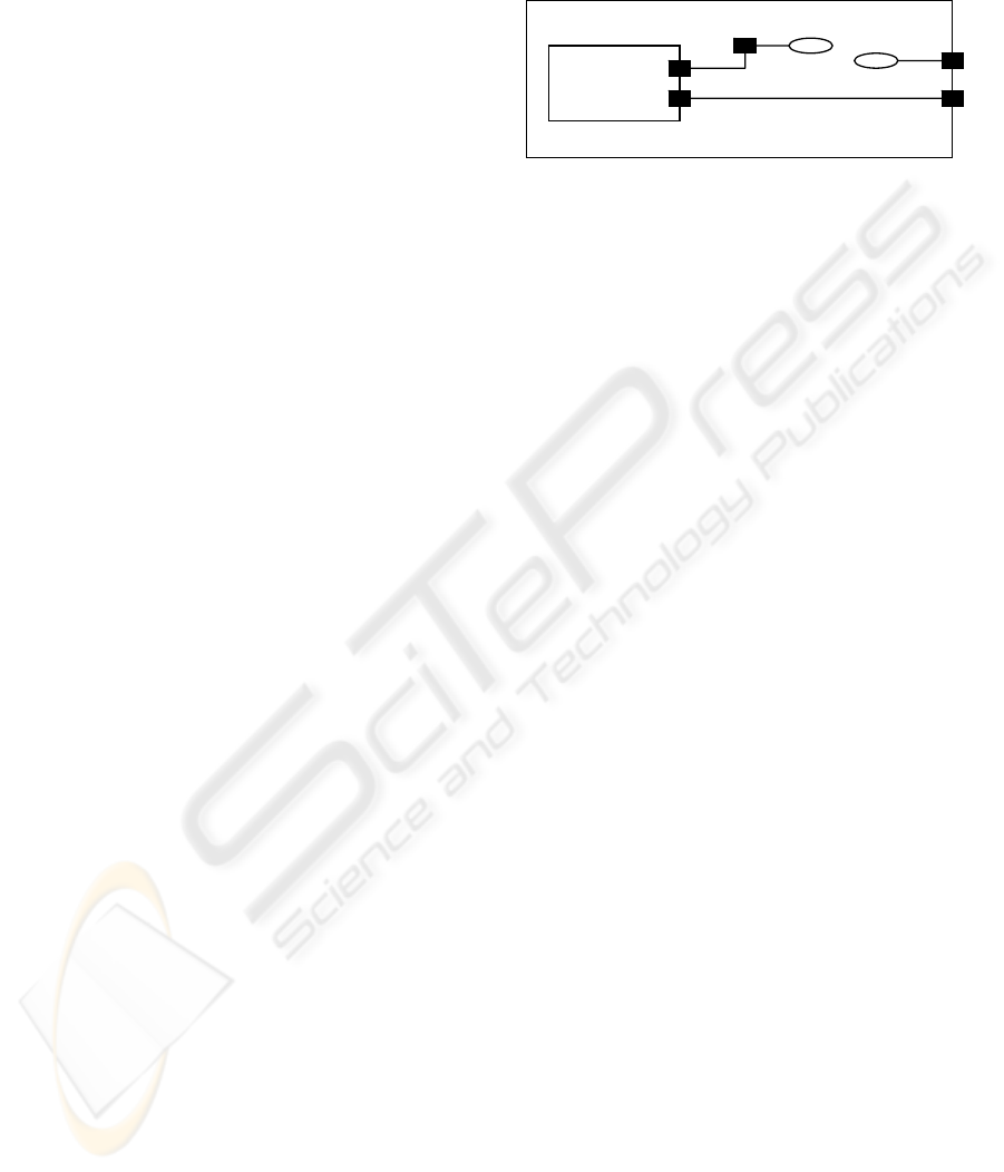
The UML extension is centred on Capsules,
Ports, and Protocols. Capsules are constructs for
isolating functionality with a very clearly defined
interface: Each capsule operates according to an
UML State Diagram (UML-SD), responding and
generating signals through its ports. The signal
contents on each port are prescribed by its role in a
protocol.
CapsB
CapsA
p3 p1
p2
Figure 1: An example of UML-RT concepts.
3 CSP+T
CSP+T extends the well-known CSP
(Communicating Sequential) formal specification
language with timing primitives. CSP is an event
based notation primarily aimed at describing the
sequencing of events within a process behaviour and
the synchronisation (or communication) between
processes. CSP+T, which is a new real-time
specification language, extends CSP (Hoare, 1978),
(Roscoe, 1997), by introducing a new set of
constructs, to allow the description of complex event
timings from within a single sequential process,
thereby providing a valuable insight into the
behavioural specification of real-time systems.
The syntax of CSP+T, which is a superset of the
CSP one, has been adapted to our method. The
differences between the two formal specification
languages are described as follows:
- Every process P defines its own set of
communication symbols, termed the communication
alphabet α(P). These communications represent the
events that process P receives from its environment
(constituted of all the other processes in the system)
or that occur internally, such as the event τ which is
not externally visible. External events can be
understood as the pure synchronization between an
asynchronous process and its environment. Any type
of event causes a state change of the process in
which it is observed.
- The communication interface comm._act(P) of
a given process P contains all the CSP-like
communications, i.e. the synchronous, one-to-one,
communications between parallel processes, in
which process P can engage and it also includes the
alphabet α(P), representing signals and events
occurring in P. Therefore, the communications of
process P are given by the set Comm-act(P)=
(Interface(P) U α(P)).
DESIGN OF REAL-TIME SYSTEMS BY SYSTEMATIC TRANSFORMATION OF UML/RT MODELS INTO SIMPLE
TIMED PROCESS ALGEBRA SYSTEM SPECIFICATIONS
291

- A new operator, ∗ (star), is introduced in the
programming notation to denote process
instantiation. An instance of a process term must be
created before it can execute. This event is unique in
the system since it represents the origin of a global
time at which processes can start their execution. As
an example, let us consider a process P that initially
can only engage in the event a. In CSP, this process
would be denoted as: P = a →STOP, but it must be
instantiated before being executed in CSP+T. Given
P', the timed version of P, which is instantiated at
time 1, where s is a time stamp associated to the
abstract communication a, the specification of P'
becomes,
P'= 1. ∗ → s.a →STOP where s ∈[1, ∞[.
It should be noted that event a occurs only once
in the interval.
- A new event operator >< is introduced to be
used jointly with a “marker variable” to record the
time instant at which the event occurs. ev>< v means
that the time at which ev is observed during a
process execution is in the marker variable v. The
value of time stamps is taken from the set of positive
real numbers, so that successive events form a non-
decreasing monotonic sequence. As several
successive events can instantiate the same variable at
different times, if we specify the process P as
follows
: P= 1. ∗ → a>< var → STOP,
for each process execution, the marker variable var
will record the corresponding time value at which
event a occurred, and it will always satisfy var > 1.
The scope of marker variables is strictly limited
to one sequential process. They cannot be referenced
or accessed in any other way within a concurrent
composition of processes.
- Each marker event is usually associated with a
time interval, which is called its “event-enabling”
interval and represents the period of time over which
the event is continuously available to the process
and its environment. During this interval, the event
can be detected, then provoking an instantaneous
change of state either in the process or in the
environment. The initial times for intervals are
relative to a preceding event or to a marker variable,
which is instantiated during current process
execution. A process is considered to be the STOP
process if it cannot engage in the marker event or in
an alternative event during the enabling interval. Let
us suppose, for instance, that there is a process P, a
process which can only engage in event a, which can
only occur between 1 and 2 units of time from the
process instantiation time (the preceding event),
recording in the marker variable v the time at which
the event a occurred. The specification of this
process is therefore,
P= 0. ∗ → [1, 2].a >< v → STOP
After the process execution, the value of the
marker variable satisfies the inequality 1 ≤ v ≤ 2.
The enabling interval can be defined in a more
compact way by using the function I, I (T,v), where
v is the marker variable that records the time instant
at which the preceding event occurred, and T defines
the duration of the time interval starting at the time
instant stored in v. An example is:
P = 1. ∗ → a><v → I(3,v).c → d → STOP
in which the event c can occur at least three time
units after the process P engages in the event a..
If the marker variable does not appear in the
signature of function I, the enabling interval is
relative to the previous marker variable in the scope
of the process, otherwise the enabling interval for
that process is considered the default interval [0,∞].
The times for events are absolute and the times for
intervals are relative to the preceding time stored in
marker variable.
- The semantics of the parallel composition of
two processes with enabling intervals which must be
synchronized depends on whether the values of these
intervals are identical, partially overlapping or
disjoint. In the first case, the processes synchronize
on the common initial events, as established in CSP
communication semantics, i.e., given
P= E1.Q and
R= E2.S, then
P//Q ≠ STOP iff α(Q)∩α(S)≠Ø ∧ E1∩E2≠Ø.
In the case of disjoint enabling intervals (E1∩E2 =
Ø), the parallel composition of processes behaves as
the STOP process.
4 THE PROPOSED
METHODOLOGY
The complexity of real-time systems have
substantially increased over the last few years, with
more and more tasks, many of them critical to the
well-being of people, which are needed to provide
the facilities demanded by their current users. Thus,
we must ensure, in the earlier phases of the
development cycle, where the error correction is
more advantageous and less expensive, that the
software behaves as expected, without leading to
potentially dangerous situations. That obviously
leads to the use of formal methods, which are
advocated as a means of providing a higher level of
confidence in the correct functioning of software.
However, formal methods are hard to master and too
expensive to be used extensively during the entire
ICEIS 2006 - INFORMATION SYSTEMS ANALYSIS AND SPECIFICATION
292

software construction process. A different approach
to the specification of a software system is taken
when semi-formal methods are used as a modelling
language. In contrast to formal methods, the semi-
formal ones do not involve all that mathematical
knowledge to be used efficiently, and UML in
particular provides a graphical mean of describing
an initial specification of the system, which is
detailed enough to satisfactorily capture the user
requirements of a RTS. UML syntax is well defined
and widely accepted in the industry, but it lacks of a
formal semantics. Thus, the combination of both
methods may take advantage of their benefits and
overcome its deficiencies if the integration scheme
between formal constructs and UML analysis
entities is well performed. Our methodology consist
of a series of transformation steps, starting the
development process by modelling the software
semi-formally (using UML-RT) and then translating
the UML model into CSP+T terms to obtain a
formal specification. This translation is performed
by means of a set of mapping rules already
established in previous works (Capel 2005a-b).
4.1 Modelling
There is a general agreement in the fact that, in order
to build systems with a guaranteed level of quality in
a cost effective manner, it is essential to construct a
global model, integrating all aspects of the system.
In order to be able to integrate temporal properties in
an early development stage of a software system, we
extended UML-SD with new annotations inspired on
CSP+T syntax. This extension deals with the use of
timing events, enabling intervals assigned to events
to restrict time execution, and a new transition
labelled with a special event, named timeout, which
triggers the system to a Skip State.
The global view is obtained by combining class
diagrams, which illustrate the architecture of
software components and the dependencies between
them, and extended UML-SDs that describe the
behavioural aspects and the state changes of each
component over the time course of a RTS model, as
it shown in figure2.
.
Behaviour 1 Behaviour 2
<<Capsule>
Capsule 1
<<Capsule>
Capsule 2
<<Protocol>>
Protocol1-2
Figure 2: RTS model.
Creating a RTS model in UML-RT using the
extended UML-SD involves performing the
following actions:
1. First of all, we define the dynamic behaviour of
all components in the system using UML SD,
then, for all the active objects, we define:
a. Initial State, the starting point of the system
b. All the states which an object passes
through
c. For all events and actions triggering state
transitions of objects, do the following steps:
i. Find the marker events and the
restricted ones
ii. Assign a special function gettime () to
the marker event, so the occurrence
instant is obtained
iii. Assign an enabling interval to the
restricted event
d. Identify all the transitions triggered by a
special timeout event, which serves to model
the situation in which a restricted event e
2
does
not occur within the enabling interval. See rule
3 of Table I as an example of this scenario
2. Create a class diagram for modelling the whole
system to show the relation between system
components:
a. Model all system components
(subsystems) as capsules
b. Model the interaction between capsules as
protocols
c. Capsule operations are private and protocol
operations are public
4.2 Transformation Rules
Obviously, the way of transforming a model
described by a semi-formal language into another
formal one, will always possess some specific
characteristics of interpretation, which may lead the
analyst to make a decision among several
alternatives. These are actually transformation rules,
see Table I, and not translation rules, since the
semantics of semi-formal and formal entities, by
definition, cannot be considered as to be
mathematically equivalent. This implies agreeing,
obviously, on the definition of a set of rules that
explain the meaning of the semi-formal elements
within the mathematical formal model.
The completeness and soundness of these rules may
only be shown if one is acquainted with the
specification of RTS.
DESIGN OF REAL-TIME SYSTEMS BY SYSTEMATIC TRANSFORMATION OF UML/RT MODELS INTO SIMPLE
TIMED PROCESS ALGEBRA SYSTEM SPECIFICATIONS
293
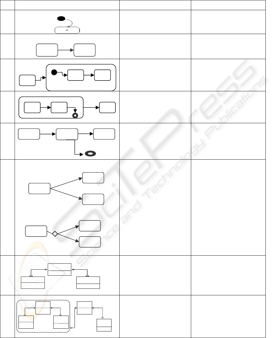
Table I: Mapping Rules from UML/RT to CSP+T.
StateChart Diagram + Class Diagram Description
CSP+T Model
1.
Initial State
Sys = 0.∗ →A
(∗: instantiation event)
2.1
Transition from a simple
State A to a simple State B
triggered by a marker event e
A = e >< m
e
→ B
2.2
Transition from a simple
State A to a Composite State
with an initial State Bi
A = e><m
e
→ Bi
2.3
Transition from a Composite
State with a final State A
f
to
a Simple State B
A
f
= e
f
→ e →B
A
f
is a final state in a
composite state
3.
(e
1
,e
2
) two successive events,
e
1
is a marker event and e
2
is
its restricted event
A = e
1
>< me
1
→ B
B = (I(T,me
1
). e
2
→ C
| I(T,me1) → Timeout
→ Skip).
4.1
4.2
External choice:
Internal choice:
The choice of which branch
to take depends on the trigger
event occurring upon exiting
from the current state
The decision on which branch
to take depends on the prior
action within the same
execution step
A= (e
1
&b
1
→B □ e
2
&b2→C)
If (e
1
≠ e
2
)
we can
write :
A= (e
1
&b
1
→B | e
2
&b2→C)
Operator □ represents non-
deterministic and operator |
represents deterministic
choice.
A=([0, T
1
].e
1
→ B) п
([T
1
,T
2
].e
2
→C )
with 0 < T
1
< T
2
5.
Prot A-B
CapsB
CapsB
Association between two
capsules sharing a protocol
Sys = {A//B}\ {E
p
}
Ep: a set of protocol
operations
If E
p
= {} then Sys = A
/// B.
6.
Prot A-B
CapsB
Prot A-B
CapsC
Sys
CapsB
Association between more
than two capsules
Sys = {A//B}\ {E
AB
}
The protocol common to
capsules A and B is hidden
from the environment
Sys1={Sys//C}\{E
AC
}
A
f
…
B
e
e
f
A B
e
e
1
e
2
A
B
C
Timeout
C
B
A
A
C
B
e
1
[b1]
e
2
[b
2
]
[0, T
1
].e
1
[T
1
,T
2
].e
2
Bi
…
A
ICEIS 2006 - INFORMATION SYSTEMS ANALYSIS AND SPECIFICATION
294

4.3 Specification
The integration of CSP+T with UML-RT provides a
precise semantics to the graphical analysis entities
offered by UML/RT, and thus opens up the
possibility of verifying a software system design by
using, for instance, the model checker FDR (Roscoe,
1997) (Formalsystems, 2005), The system
specification in terms of CSP+T serves as a bridge
between the abstract, user level, graphical, UML
specification of the system and its detailed design
and final implementation.
The transformation is obtained by applying a set of
mapping rules shown in Table I. In order to do so,
we follow a procedure consisting of the following
steps:
1. Transform each SD diagram into a CSP+T
process
a. Map each state into a CSP+T process, the
initial state is assigned to a process term that
includes the instantiation event (rule 1), which
gives the global time origin
b. Transition from P to Q, triggered by a
marker event e, is translated into the CSP+T
process
P= e>< te → Q, being te the instant
of the event occurrence, this mapping is
summarized as rule (2).
c. There are two possible representations of
choices: a choice state (represented as a
diamond shape) or a normal state with more
than one outgoing transition. In the choice
state, the decision on which branch to take next
depends on the prior actions performed by the
process within the same execution step. In a
normal state, the choice depends on the trigger
event that occurs upon exiting from the current
state (rule 4)
2. To combine the individual processes obtained in
step 2, we transform the system class diagram
into CSP+T processes,
a. Treat each capsule as a CSP+T process
b. Capsule operations become the internal
events of the process
c. Protocol operation denotes the
communication between two capsules, or in
other case the signals shared between two
processes
d. Two associated capsules are presented as
two processes composed in parallel with all the
events in their common protocol hidden (rule
5)
e. Processes associated to the classes are
progressively composed in parallel and the
operations appearing in the associated protocol
become hidden (rule 6)
f. The transformation finishes when all the
classes are composed and all internal events
(private operations) are hidden.
4.4 Refinement
A kind of model transformation named refinement is
usually performed at the design stage of complex
systems. Refinement serves to tackle design
complexity and to potentially improve reuse of
software packages by defining an interface for each
package. There are two participants involved in a
refinement action, the abstract specification and the
concrete specification. The abstract interface
specifies to the classes outside the package how it
can be used without knowing the concrete
specification of the package.
The final set of operations chosen to model the
system behaviour, representing the abstract
specification, and the concrete specification that
groups all the system classes into a package, are
shown in figure 3.
Spec
<<T>>
Imp Sys
Figure 3: UML Refinement.
Refinements are the primary focus of analysts’
attention during design reviews, inspections, and
testing tasks within the design stage of software.
The transformation of the concrete specification
into the abstract specification in figure 3 can be
written in CSP terms as it follows:
Spec [T = Imp_Sys \{hidden events}
The hidden events are all these events within the
system classes which are not public.
5 PRODUCTION CELL:
USE CASE
The Production Cell (PC) (Lindert, 1995) processes
metal blanks which are conveyed to a press by a
feed belt. A robot arms takes each blank from the
feed belt and places it on the press, then the robot
arm withdraws from the press proximity, the press
processes the metal blank and opens again. Finally,
DESIGN OF REAL-TIME SYSTEMS BY SYSTEMATIC TRANSFORMATION OF UML/RT MODELS INTO SIMPLE
TIMED PROCESS ALGEBRA SYSTEM SPECIFICATIONS
295
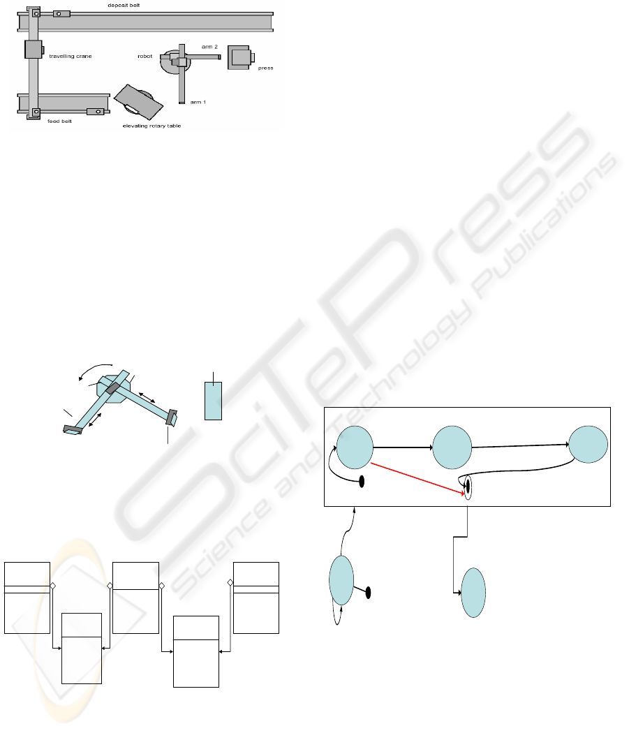
another robot arm takes the forged metal plate out of
the press and puts it on a deposit belt, as it is shown
in Figure 4.
Figure 4: Production Cell.
5.1 Modelling the Robot
The robot comprises two orthogonal arms. Each arm
can retract or extend horizontally. The end of each
robot arm is fitted with an electromagnet that allows
the arm to pick up metal plates. The robot’s arm task
consists in taking metal blanks from the elevating
rotary table to the press and transporting forged
plates from the press to the deposit belt.
electromagnets
Electric
motor
arm1
robot
Electric
motor
Press
arm2
Figure 5: Robot and press (top view).
The Robot Class Diagram, Figure 6, shows the
robot architecture, the interaction between the robot
controller and the two arms of the robot.
<<Capsule>>
Arm1
<<Capsule>>
Arm2
<<Capsule>>
Robot-Controller
<<Protocol>>
P-Arm1
<<Protocol>>
P-Arm2
-Getposition
-Turn
+ Extend1
+ Load1
+Unload1
+ Retract1
+Stop1
+ Extend2
+ Load2
+Unload2
+ Retract 2
+Stop2
Figure 6: the Robot class Diagram.
Applying rule 6 in Table I, we obtained a
specification of the subsystem composed by the
Robot Controller and Arm1.
RobotController-Arm1 =
(Robot controller // Arm1)
\{A1Extend, A1Retract, A1Load,
A1Unload, A1Stop}.
By composing in parallel the processes
RobotController-Arm1 with Arm2 we obtain the
Robot process structure (Rule 6, Table 1):
Robot = (Robotcontroller-Arm1 // Arm2)
\{A2Extend, A2Retract, A2Load,
A2Unload, A21Stop}.
A normal work cycle of the robot can be
described in four main steps. We single out here the
clockwise robot rotation until Arm 1 is faced to the
table, when it extends and picks up a metal blank
from the table. To avoid collision between arm 1 and
the press, we store in a variable tpos1 the time at
which the robot arrived to a given position. We
assign an interval
I [TCU, tpos1] to the event
which warns the controller that the component is
ready to be unloaded. The arm can extend only if the
event occur within the enabling interval, or
otherwise the timeout event is triggered and the
robot exits the actual state and turns towards another
position to complete its task. To allow safe rotation,
the arm must be retracted before the robot can turn.
These concepts are integrated in SD diagram as it is
shown is Figure 7.
WFT
WA1R
a1extended ^ a1.Stop ^ a1.Load ^ retract
Tex=gettime tload=gettime
I.a1retracted ^ a1.Stop ^ Table.unloaded
timeout
TableReady ^ a1.Extend
Ttr= gettime
WA1E
CWW
Turn(left)
CW
Start
Pos1 ^ turn(Stop)
Tpos1=gettime
Figure 7: Robot Controller Statecharts diagram (one
composite state).
Applying the mapping rules from fig.7 to CSP+T we
obtain :
Robot-Controller = RC
RC = Start → CW
CW = Pos1 >< t
pos1
→ WFT
ICEIS 2006 - INFORMATION SYSTEMS ANALYSIS AND SPECIFICATION
296
WFT = ((I (T
TR
, t
pos1
).TableReady >< t
tr
→
A
1
.extend) → WA
1
E
1
) | I (T
TR
, t
pos1
) →
TIMEOUT → Turn (left) → CWW
WA
1
E
1
= I (T
EX
, t
tr
).A
1
Extended ><t
ex
→
A
1
.stop → I (T
load
, tex).A
1
.load ><t
load
→
WA
1
R
1
WA
1
R
1
= (I (T
ret
, t
load
) .A
1
retracted
→
A
1
.stop →Table.Unload → Turn (left)
→CWW
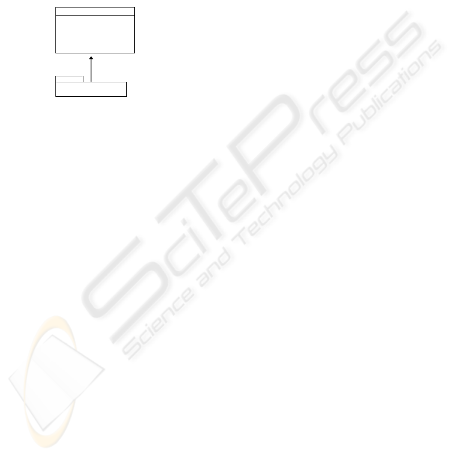
The robot refinement behaviour is described in UML
by:
Spec(Robot)
Extend
Retract
Load
Unload
Stop
<<T>>
Imp(Robot)
Figure 8: Robot Refinement.
The robot controller and the two arms are
grouped under package named Imp(Robot), the
operation in the Spec(Robot ) represent the protocol
operation in Robot class diagram, figure 6.
Spec_Rt [T = Imp_Rt \{turn, getpos}
The hidden operation is the capsules operation in
robot class diagram.
6 CONCLUSION
We have presented a systematic method to derive a
correct system specification in terms CSP+T from a
semi-formal model described in UML-RT. The
proposed method takes advantage from the benefits
of the two languages combined and overcomes the
drawbacks of using only one of them when
designing software for RTS. The future and ongoing
work in our project is aimed at using the proposed
method for automatic code generation of embedded
control real-time systems. CSP+T will serve as a
bridge between the high-level graphical UML model
and the final implementation. Java code is obtained
from a CSP+T specification, which is automatically
generated from the UML-RT graphical model of the
intended system, by using the tool CSPJade
(Escamez, 2005) that is being developed in our
laboratory.
REFERENCES
B.Selic and J.Rumbaugh, 1998. “UML for modeling
complex real-time systems”. Technical report,
ObjectTime.
Booch, James Rumbaugh, and Ivar Jacobson. 1999. The
Unified Modeling Language User Guide. Addison-
Wesley, Reading, Massachusetts, USA,
Capel. M.I, Holgado.J.A, 2005 “Transforming SA/RT
Graphical Specifications into the CSP+T Formalism-
Obtaining a Formal Specification from Semi-Formal
SA/RT Essential Models”, ICEIS 2005, v.3, Miami,
USA, May 25-28, pp.65-72.
Capel. M.I, Benghazi .k, Holgado.J.A, 2005 “Combining
the Description Features of UMLRT and CSP+T
Specifications Applied to a Complete Design of Real-
Time Systems” IJIT volume 2 number 2 ISSN: 1305-
2403, pp-137-146.
Escamez A, Capel M. I.; Holgado J.A.; 2005 “An
Integration Scheme For CPN And Process Algebra
Applied To A Manufacturing Industry Case”, OMSPN,
1-10.
Fisher, C., Orlog, E.R ,Olderog, H., Wehrheim, (2001): A
CSP view on UML-RT Structure diagrams. In.
Proceeding of the 4
th
International Conference on
Integrated Fundamental Approaches to Software
Engineering , Springer .
FormalSystems, 2005, FDR2.82 released.
http://www.fsel.com.
Hoare, C.A.R, 1978. Communicating Sequential
Processes, Prentice- Hall, Englewood Cliffs
Lindert, 1995 Formal Development of reactive Systems:
Case Study Production Cell. LNCS 891. Springer
Verlag.
Möller, M., Olderog, E.R., Rash, H., Wehreim, H. (2004):
Linking CSP-OZ with UML and Java: A Case Study.
In: 4
th
ICIFM. Volume 2999 of LNCS. Springer .
Ng, MY., Butler, M.J.: Towards Formalizing UML State
Diagrams in CSP. In: 1
st
International Conference on
Software Engineering and Formal Methods, IEEE
Computer Society (2003)
OMG, UML/RT Profile for Schedulability, Performance,
and Time Specification, OMG Documents ptc/ 2003-
03-02, March 2003.
OMG. Response to the OMG RFP for schedulability,
performance, and time, June 2001. OMG document
number: ad/ 2001-06-14, http://www.omg.org/cgi-
bin/doc?ad/2001-06-14.
Ramos, Sampaio, Mota. 2005: A semantics for UML-RT
Active Classes via Mapping into Circus. 7th IFIP WG
6.1 International Conference on Formal Methods for
Open Object Based Distributed Systems, Vol. 3535,
pp. 99-114.
Roscoe. 1997 the theory and practice of concurrency.
Prentice Hall.
Zic, 1994 “Timed constrained buffer specifications in CSP
+ T and timed CSP”. ACM Transaction on
Programming Languages and Systems, vol.16, 6, pp.
1661-1674.
DESIGN OF REAL-TIME SYSTEMS BY SYSTEMATIC TRANSFORMATION OF UML/RT MODELS INTO SIMPLE
TIMED PROCESS ALGEBRA SYSTEM SPECIFICATIONS
297
