
A PRODUCT ORIENTED MODELLING CONCEPT
Holons for Systems Synchronisation and Interoperability
Salah Baïna, Hervé Panetto
CRAN (UMR 7039), University Henry Poincaré Nancy I
F 54506 Vandoeuvre les Nancy, France,
Khalid Benali
LORIA (UMR 7503), Campus scientifique, BP 239
F 54506 Vandoeuvre les Nancy, France,
Keywords: Process Modelling, Models Synchronisation, Manufacturing Systems, Enterprise Integration, Systems
Interoperability, Model Driven Architecture, Models Mapping.
Abstract: Nowadays, enterprises are confronted to growing needs for traceability, product genealogy and product life
cycle management. To meet those needs, the enterprise and applications in the enterprise environment have
to manage flows of information that relate to flows of material and that are managed in shop floor level.
Nevertheless, throughout product lifecycle coordination needs to be established between reality in the
physical world (physical view) and the virtual world handled by manufacturing information systems
(informational view). This paper presents the “Holon” modelling concept as a means for the synchronisation
of both physical view and informational views. Afterwards, we show how the concept of holon can play a
major role in ensuring interoperability in the enterprise context.
1 INTRODUCTION
Enterprise application integration (EAI) and the
opening of information systems towards integrated
access have been the main motivation for the interest
around systems interoperability. Integration aspect
and information sharing in the enterprise lead to an
organisation of the hierarchy of enterprises
applications where interoperability is a key issue
(see
Figure 1).
Figure 1: Manufacturing enterprises common structure.
This hierarchy defines the three main levels in
manufacturing enterprises:
L1: Process control level contains all processes that
perform routing and physical transformations on the
produced goods and services;
L2: The Execution level performs the processes that
manage decision flows (e.g.: Workflow systems)
and production flows (
e.g.: MES
1
, SCE
2
);
L3: The management system level is responsible
for the management of processes that handle all
different informational aspects related to the
enterprise (
e.g.: APS
3
, ERP
4
or CRM
5
systems).
To meet traceability, product genealogy and
product life cycle management needs, nowadays an
enterprise has to manage flows of information that
relate to flows of material and that are managed in
shop floor level.
We assume that the enterprise is
composed of two separated worlds (see
Figure 2:):
1
Manufacturing Execution System
2
Supply Chain Execution
3
Advanced Planning Scheduling system
4
Enterprise Resource Planning
5
Customer Relationship Management
MANUFACTURING
MANUFACTURING
EXECUTION
EXECUTION
SYSTEMS
SYSTEMS
ERP
W
ORKFLO
W
W
ORKFLO
W
MANAGEMENT
MANAGEMENT
SYSTEMS
SYSTEMS
PROCESS CONTROL
PROCESS CONTROL
FO
R
FO
R
GOODS & SERVICES PRODUCTION
GOODS & SERVICES PRODUCTION
MANUFACTURING
MANUFACTURING
EXECUTION
EXECUTION
SYSTEMS
SYSTEMS
ERP
W
ORKFLO
W
W
ORKFLO
W
MANAGEMENT
MANAGEMENT
SYSTEMS
SYSTEMS
PROCESS CONTROL
PROCESS CONTROL
FO
R
FO
R
GOODS & SERVICES PRODUCTION
GOODS & SERVICES PRODUCTION
L2
L3
L1
19
Baïna S., Panetto H. and Benali K. (2006).
A PRODUCT ORIENTED MODELLING CONCEPT - Holons for Systems Synchronisation and Interoperability.
In Proceedings of the Eighth International Conference on Enterprise Information Systems - ISAS, pages 19-26
DOI: 10.5220/0002455400190026
Copyright
c
SciTePress
(i) On one hand, a world in which the product is
mainly seen as a physical object, this world is
called the manufacturing world. It handles systems
that are tightly related to the shop-floor level,
(ii) On the other hand, a world where the product is
seen as a service released in the market. This world
is called the business world.
In order to achieve the main objective of the
enterprise, "the product" to be specific, the business
universe and the manufacturing universe need to
exchange information and to synchronise their
knowledge concerning the product (good and
service). It is assumed that the product
(good/service) can play the role of the gateway
between both universes, since it represents a
common entity between those worlds.
Figure 2: Product centric approach.
In this paper, we define a holon based approach
in order to synchronise views in the business world
and in the physical manufacturing world using the
holon concept. The paper continues by presenting
the usability of the concept of holon in ensuring
interoperability enterprise context. Section 2
presents the bases of our holonic process modelling
concepts (Morel, et al., 2003) that use the product as
a centric entity in process models. Section 3 of the
paper gives a brief introduction to interoperability in
the enterprise and explains how holons can be used
as a means for enterprise applications
interoperability. In Section 4, an implementation of
the holon is proposed. Section 5 gives conclusions
and perspectives for this work.
2 A MODELLING CONCEPT FOR
PRODUCT REPRESENTATION
In this section, we introduce the holon as a
modelling concept. Afterwards, we will show how
this concept can be exploited in order to facilitate
taking into account interoperability concerns in
modelling phase. Existing solutions for
interoperability in enterprise environment focus
mainly on enterprise processes interoperability and
interconnection. Throughout product lifecycle,
coordination needs to be established between the
reality in the physical world where the product
evolves as a physical object and the “electronic”
world handled by manufacturing information
systems where the virtual image of the product
evolves as an informational object. Our work aims to
provide a product centric approach for enabling
interoperability between information systems in the
manufacturing environment in order to establish the
coherence between the physical products and their
informational representations. To take into account
this duality (physical things/ informational things),
we propose an adaptation of the concept of holon
(Koestler, 1967) to this specific problem.
The word Holon is a combination of the Greek
word holos, meaning whole, and the suffix on
meaning particle or part. A holon is an identifiable
part of a system that has a unique identity, yet is
made up of sub-ordinate parts and in turn is part of a
larger whole. A Holon has two main features,
autonomy and cooperation. Several adaptations of
the holon concept have been proposed in several
fields. In the manufacturing context, a Holonic
Manufacturing System (HMS) is an autonomous and
co-operative building block of a system for
transforming, transporting, storing and/or validating
information and physical objects (Mc Farlane and
Bussmann, 2000; Seidel and Mey, 1994). In this
paper, we adapt the holon concept definition to solve
the problem of synchronisation between physical
views and informational views of the same objects.
We define the holon then as an aggregation of an
information part and a physical part.
In Holonic Process Modelling (Valckenaers,
2001; Morel, et al., 2003; Baïna, et al., 2005),
holons are used to represent products; the physical
part of the holon represents the material part (also
called physical view) of the product and the
informational part of the holon represents the
informational part (informational view) of the
product. Characteristics of holon are distinguished
into two categories;
- Attributes describing the current state of the holon.
The state of a holon contains three kinds of
attributes: space attributes, shape attributes, and
time attributes (Panetto and Pétin, 2005);
ERP
A
PS
CRMERP
A
PS
CRM
Business world
MES
SCE
MES MES
SCESCE
Product (Good/Service)
Manufacturing world
ICEIS 2006 - INFORMATION SYSTEMS ANALYSIS AND SPECIFICATION
20
- Properties related to the holon but which do not
correspond to any of the three types of properties;
space, shape or time.
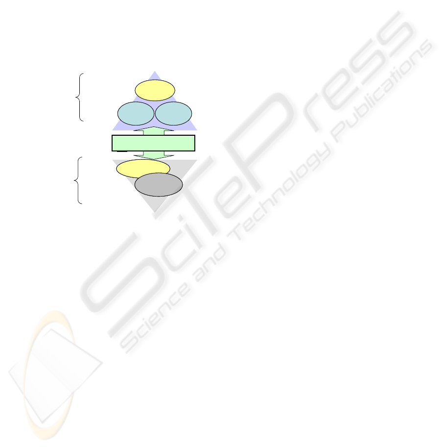
Holons can be classified into two categories; (i)
elementary holons and (ii) composite holons:
(i) Elementary holons are the combination of a
single informational part and a single physical
part.
(ii) Composite holons are the result of the processing
and treatment of one or more other holons, this
processing can be the aggregation of a set of
holons (composite or elementary) in order to
compose a new holon or a transformation of one
composite holon to obtain a new one.
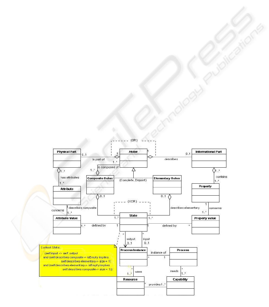
Figure 3 represents the UML class diagram
defining the holon concept meta-model. In order
save place and limit the complexity, in this meta-
model, we have not represented the many constraints
that apply between classes and that are specified
using the OCL language as defined in UML
specifications (UML, 2005).
Here is a brief description of this class diagram: The
Class Holon defines basic attributes for both
composite and elementary holons. A Physical Part
is a reference to the physical part encapsulated in a
holon. An Elementary Holon is defined as a holon
with no indication about his lifecycle. For example a
product, produced by external manufacturing
systems does not give information about the
processes needed for its manufacturing. A
Composite Holon is a holon that has been obtained
by either by assembling existing holons, or by
disassembling existing holons into new ones.
The state class defines the different states that
have been observed during the processing phase of
the holon. Every manipulation of a holon through a
process (Process Instance) implies a change in the
state of the processed holon. A Property of a holon
contains information that can not be handled only
using its state. The Process instance refers to the
execution of a process on a single holon, this class
enables description of the execution of the process
with high level of detail (e.g.: elapsed time, start and
end of the treatment, used equipment, needed
personal). A Process instance input is a holon state
A Process describes an internal process that is
performed inside the studied domain. The Resource
class describes resources needed to perform a
process instance. A resource can be a material
resource, a software resource or a human resource.
Each resource provides a set of capabilities, and
each process needs some capabilities to be
performed.
3 HOLONS AND
INTEROPERABILITY
The ISO/IEC 23821 Information Technology
Vocabulary defines interoperability as “the
Figure 3: Class diagram for the Holon model.
A PRODUCT ORIENTED MODELLING CONCEPT - Holons for Systems Synchronisation and Interoperability
21

capability to communicate, execute programs, or
transfer data among various functional units in a
manner that requires the user to have little or no
knowledge of the unique characteristics of those
units.” The IEEE STD 610.122 standard defines
interoperability as “the ability of two or more
systems or components to exchange and use
information”. In this paper, interoperability
definition is adapted from the two previous
definitions as:
Definition 1: Interoperability is the ability to
communicate, to cooperate and to exchange models
between two or more applications despite
differences in the implementation languages, the
execution environments, or the models abstraction
(Kalfoglou and Schorlemmer , 2004)
Interoperability can be classified into two
categories considering the enterprise hierarchy
model:
”Horizontal Interoperability” is the interoperability
between applications from the same conceptual level
in the enterprise. This first category of
interoperability aims to synchronise models that
were created in different enterprises even those
managed by different modelling systems (e.g.:
enabling organisational interoperability between two
systems used in two different organisations).
”Vertical interoperability” is the interoperability
between applications from different enterprise
levels. The objective of this category of
interoperability is to maintain coherence between
information that is handled in two different level of
the enterprise (e.g.: ensuring coherence between
organisational models of the enterprise and the
process models used at shop floor level).
The following introduces the Levels of
Conceptual Interoperability Model (LCIM). Similar
to the technical approaches, five levels of
interoperability are defined (Tolk and Muguira,
2003). The focus lies on the data to be interchanged
and the interface documentation, which is available.
The layers are defined as follows:
Level 0 - System Specific Data: No interoperability
between two systems. Data is used within each
system in a proprietary way with no sharing. The
component (or application) is a black box.
Level 1 – Documented Data: Data is documented
using a common protocol and is accessible via
interfaces. The component is a black box with an
interface.
Level 2 – Aligned Static Data: Data is documented
using a common reference model based on a
common ontology, i.e., the meaning of the data is
unambiguously described. This is also possible by
using metadata standards or by using standard
reference models. The component is a black box
with a standard interface.
Level 3 – Aligned Dynamic Data: The use of the
data within the federate/ component is well defined
using standard software engineering methods such
as UML. This shows the use of data within the
otherwise unknown “black box behind the
interface,” also known as white box.
Level 4 – Harmonized Data Semantic:
connections between data that are not related
concerning the execution code is made obvious by
documenting the conceptual model underlying the
component.
In order to take into account interoperability
requirements during modelling phase in the context
of manufacturing systems, we introduce, in this
section, the holonic modelling approach for
interoperability. Existing interoperability standards
and most of existing techniques that enable business
process or workflow interoperability are based on a
message exchange paradigm (e.g. Wf-XML,
BizTalk, FIPA ACL.). These solutions resolve only
the particular case of syntactic interoperability
(messages vocabulary, messages format, data types,
etc). In this section, we show how the holon concept
can be used as a means for resolving interoperability
issues. First, we will show the use of the holon to
handle horizontal interoperability concerns at
modelling time. Second, the case of vertical
interoperability is studied.
3.1 Holons for Horizontal
Interoperability
Horizontal interoperability problem occurs when
two or several systems or applications from the same
level in the enterprise hierarchy (see figure 1) need
to exchange information or data in order to perform
a common objective. For example, we consider the
case of a manufacturing shop-floor where several
manufacturing systems need to cooperate in order to
achieve a common goal, the release of the final
product to be specific. In this section, we show how
the use of the holon concept in the modelling phase,
enables considering vertical interoperability
concerns at modelling time; in the aim to facilitate
resolving interoperability problems during
engineering phase.
ICEIS 2006 - INFORMATION SYSTEMS ANALYSIS AND SPECIFICATION
22
To model manufacturing shop-floor, we use a
minimal business process meta-model composed of
four Entities:
Actor: represents a person or a group of persons
that act in someway on processes or in the
information system of the enterprise. An actor can
be internal or external to the enterprise.
Process: a value chain that provides a good or a
service to an internal or external customer.
Site: a geographic place where the enterprise is
established. Sites can express a special kind of
places such as agency, office and factory, or can also
express precise geographic places.
Flow: a set of elements (data, information, energy,
material ...) that are exchanged between processes
To those entities, we add the notions of Holon
which represents products instances. As we see in
section 2, a holon is described by properties and
attributes that are mandatory for controlling the
execution of a process on the holon. To manipulate
those pieces of information we assume that each
process is indeed composed of two interdependent
sub-processes: (i) An informational process is
responsible of manipulating, updating and
controlling the information concerning the product
(holon), this informational process can be
implemented by an application that is performed on
the information contained in the product, (ii) a
physical process that performs all physical
transformations on the material of the product.
Those two sub-processes are performed in an atomic
operation (both are executed or none). Two types of
relationships between a process and a piece of
information (property or attribute) have been
identified: production and consumption;
- Production: we say that a process produces an
attribute (or property) when the attribute did not
exist before the execution of the process;
- Consumption: a process is said to be consumer of
an attribute (or property) when it uses the
attribute (or property) or updates it.
The specification of relationships between
processes and pieces of information during
modelling phase enables defining the interfaces of
processes at modelling time. The interface of a
process defines its inputs and outputs.
Using those interfaces, interoperability of
processes using can then be defined as explained in
the following:
Definition 2: A process P is said interoperable with
a system S (composed of processes) iff each input of
P is declared as an output of one of his predecessors
in S.
The precedence relation between processes is
defined as following:
Definition 3: The relation of precedence is partial
order between processes; we say that a process P1
precedes a process P2 (P1 <
Pred
P2) if it exists a path
composed of flows and processes that leads from P1
to P2. In the case cyclic systems, occurrences of
execution of processes should be considered;
example P1
i
<
Pred
P2
i
the i
th
execution of P1 occurs
before the i
th
execution of P2.
Using the holonic modelling concepts in
manufacturing context, enables the considered
process interoperability to be concerned at
modelling time and not during the engineering
phase. This interoperability is a vertical integration
of processes, since all process (informational and
physical) involved in the studied system are from the
same enterprise level, the process control level to be
specific. The obtained interoperability is categorised
into level 1 of the LCI model (see section 3), it
defines interfaces for shop floor process, that are
seen as black boxes, since the designer does not
know in advance their internal structure and
characteristics.
3.2 Vertical Interoperability with
the MDA Approach
In this section, we introduce an approach for
interoperability based in a model driven architecture
(MDA) (Breton and Bézivin, 2001; Mellor, et al.,
2004). The main objective of this section is to show
how models based on the holon concept defined in
section 2, could be expressed and transformed into
models based on existing data exchange standards
and other unified languages.
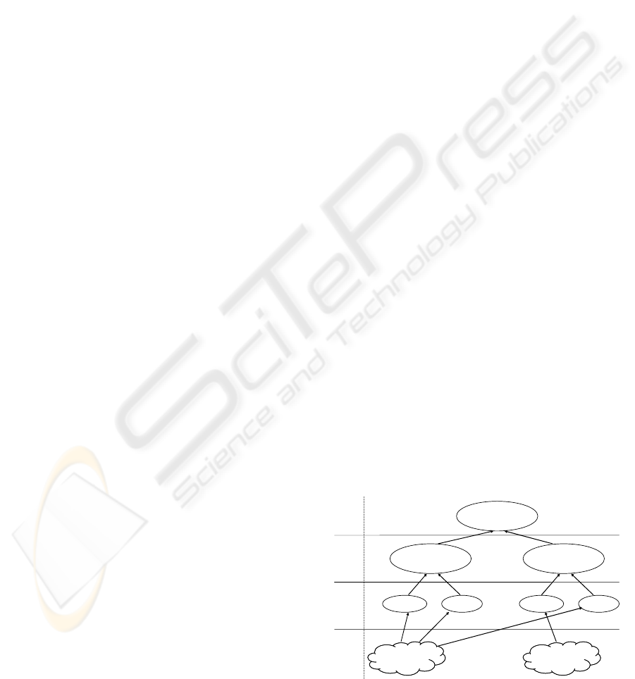
Figure 4 shows the four-level ontological
approach levels for modelling that are used in the
MDA.
Universe of
discourse 1
Universe of
discourse 1
…
…
…
Meta-Meta-Model
Meta-Model 1 Meta-Model p
Model 1
1
Model k
1
Model 1
p
Model m
p
Level M
3
Level M
2
Level M
1
Level M
0
Universe of
discourse n
Universe of
discourse n
…
Figure 4: The four-level ontological approach.
A PRODUCT ORIENTED MODELLING CONCEPT - Holons for Systems Synchronisation and Interoperability
23

As it is explained in (Naumenko and Wegmann,
2003), the lowest level M
0
presents different subjects
for modelling, called universe of discourse. The level
M
1
contains different models of each universe of
discourse. The next level M
2
presents domain
specific meta-models: one meta-model for each of
the domains of interest relevant for the M
1
models.
And finally, M
3
level presents a meta-meta-model
designed to allow the definition of all the existing in
the scope of the meta-models. In this context,
applications interoperability may be solved by a top-
down approach based on the four levels of the MDA.
Indeed the MDA approach for interoperability relies
on meta-models mapping to determine, establish and
measure interoperability between applications.
Several research works have been done in order to
resolve meta-models mappings, more generally
ontology mappings problems (Kalfoglou and
Schorlemmer, 2004).
R Lemesle, in (Lemesle, 1998), explains how
models transformation can be resolved by
establishing transformation rules between meta-
models. Those transformation rules define a mapping
that guides model transformations from the instances
of the source meta-model to instances of the target
meta-model. Those mappings are the bases for
applications interoperability. In the MDA approach
for applications interoperability, we consider that
each application is based on a specific meta-model;
Let us consider two applications A and B: A and B
are interoperable, if and only if there is a mapping
from the meta-model of A (M
A
) to the meta-model
of B (M
B
) and a mapping form M
B
to M
A.
Those
mappings ensure that we can build a model
compatible with A from a model used by B (and vice
versa).
In Order to use the MDA approach for
interoperability in the holonic context, we need to
define roles played by the holon in this structure,
and to position the holonic modelling approach in
terms of models, meta-models and universe of
discourse: M2, M1 and M0. In the holonic context,
the universe of discourse M0 concerns "The
Manufacturing Enterprise Product Universe", to
describe this universe of discourse we use holonic
models (M1) that are instantiations of the holonic
meta-model defining holons and their relationships
with other entities in their environment (M2).
Defining interoperability mappings between the
holonic meta-model and other meta-models that
handle product information enables the holonic
meta-model to play the role of a gateway between
those meta-models. Indeed, the holonic meta-model
can be seen as a reference model for product
representation.
In the next section, an implementation of the
holonic model and the interoperability mappings is
proposed. This implementation relies on a
commercial computer assisted software engineering
(CASE) tool.
4 IMPLEMENTATION
To experiment the holonic approach defined above
in real case we have implemented this approach into
a CASE tool named MEGA Suite
6
. MEGA is an
enterprise process modelling environment that
contains a business process analysis and process
modelling and design tools. MEGA has its own
meta-model that described all concepts and objects
ready to use in MEGA, and all relationships that
exist between those concepts. This meta-model can
be customized and specialised for specific users
needs. MEGA Suite can be used to define, describe
and exploit several kinds of diagrams (e.g: Business
process Diagrams, UML Diagrams, Workflows). In
our contribution, we focus only on business process
diagrams; indeed they seem to be the most adequate
choice for holon integration. Business Process
diagrams in MEGA are based on a meta-model
inspired from BPMN
7
. MEGA offers tools that
enable customizing the meta-model; we used these
tools to embed our own holon meta-model into the
existing meta-model of MEGA in order to test the
usability of our proposal.
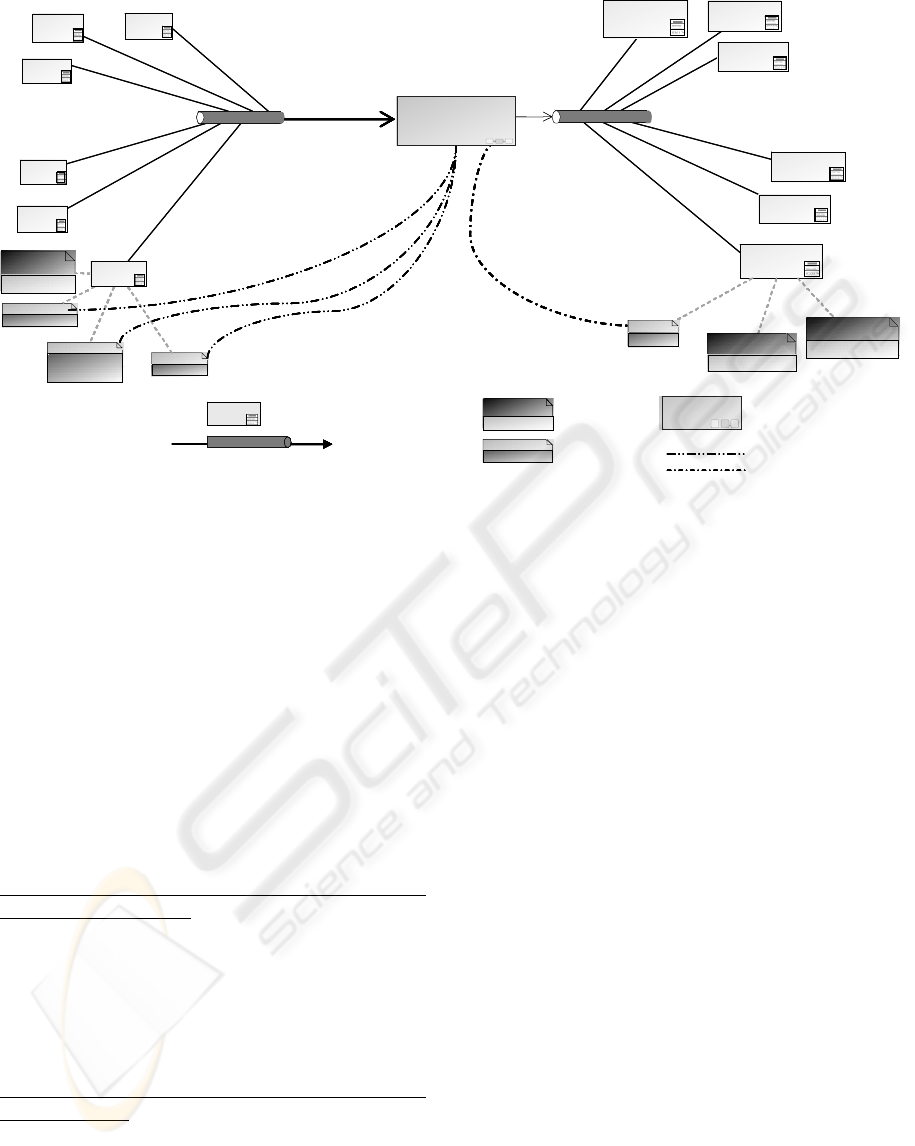
The example presented in Figure 5 shows an
example of models that can be designed using the
holon modelling concept to represent products in a
manufacturing process model. For the sake of
simplicity, this example contains only one single
process that takes a holon flow as input, and
produces a holon flow as output.
In this example, we show using the implementation
of the holonic concepts in MEGA, how a process
can be connected to information and data concerning
holons (inputs or outputs). The holons in this
example represent products (finished or not).
6
MEGA Suite, MEGA International, www.mega.com
7
Business Process Modelling Notation, www.bpmn.org
ICEIS 2006 - INFORMATION SYSTEMS ANALYSIS AND SPECIFICATION
24
To experiment the holon models interoperability
with other enterprise modelling frameworks using
the MDA approach, two examples have been
chosen; UEML and B2MML. UEML (Berio, et al.,
2003; Panetto, et al., 2004) is the Unified Enterprise
Modelling Language, it is used at the organisational
level of the enterprise. B2MML (2003) is an
implementation of the part 1 of the IEC FDIS 62264
standard (IEC 62264, 2002) developed for
interfacing the manufacturing control and execution
systems with higher level systems. According to the
MDA interoperability approach defined in section
3.2, we now define an example of mappings from
the holonic meta-model to The UEML and B2MML
meta-models.
Mapping Holon with the Unified Enterprise
Modelling Language. The Unified Enterprise
Modelling Language (UEML) is the result of the
UEML project (UEML, 2003). The UEML is an
Interlingua between Enterprise Modelling tools. The
meta-model of UEML1.0 (Panetto, et al., 2004)
defines the set of most relevant concepts and notions
for Enterprise modelling.
Mapping with the B2MML language and the IEC
62264 standard. Business to Manufacturing Mark-up
Language (B2MML) is an XML implementation of
the IEC 62264 part 1. This standard is composed of
six different parts designed for defining the models
and interfaces between enterprise activities and
control activities. Each model concerns a particular
view of the integration problem. Those models show
increasing detail level in the manufacturing system.
The detail of those mappings has been published
in other papers, for further information see Baïna, et
al (2005). Vertical interoperability that is established
by using those mappings is classified in the Level 2
of the LCI model. (see section 3).
To implement the mappings from the holonic
models designed in MEGA and the other formats,
we first define an extraction format that expresses
data extracted from MEGA holon models in order to
reuse it in other tools and frameworks based on other
meta-models (UEML, B2MML, etc.). To represent
the extracted data, we choose the XML language
(
XML, 2002); since it is considered as the standard
application data exchange language by the W3C.
MEGA Suite enables XML files generation in
respect to a specific structure. XML structures for
UEML (Berio et al., 2003), and B2MML (B2MML,
2003) are used to transform the mappings defined
below into XSLT rules that can be applied on the
files generated by MEGA in order to restructure
them into files that respects the UEML structure or
the B2MML structure.
5 CONCLUSION
In this paper, we defined an approach for specifying
the holon modelling concept, it enables maintaining
synchronisation between the physical objects and
Figure 5: An example of models containing holons.
InPutInPut
OutPut
Prod 01,09
Prod 60,10
Prod 60,08,09Prod 60,08,09
Prod 01,11,10
Prod 60,08,11,10
Prod 01,11,08,09
P01
P10
P09
P60
P11
property
Client
attribute
S
couleur
attribute
T
Date fabrication
attribute
Matiere
P08
property
num piece
property
Client
Assembling
attribute
Prod
HolonHolon
Holon FlowHolon Flow
Holon representation
Holon flow: transporting
holon instances
Holon property
Holon attribute
Process
Assembling
Consumption
Production
InPutInPut
OutPut
Prod 01,09
Prod 60,10
Prod 60,08,09Prod 60,08,09
Prod 01,11,10
Prod 60,08,11,10
Prod 01,11,08,09
P01
P10
P09
P60
P11
property
Ref Client
attribute
S
Color
attribute
T
Manufacturing
Date
attribute
Matiere
P08
property
Ref piece
property
Ref Client
Assembling
attribute
HolonHolon
Holon FlowHolon Flow
Holon representation
Holon flow: transporting
holon instances
Holon property
Holon attribute
Process
Assembling
Consumption
Production
Manuf Date
Property
property
Client
property
Property name
attribute
Matiere
Attribute
Attribute name
A PRODUCT ORIENTED MODELLING CONCEPT - Holons for Systems Synchronisation and Interoperability
25

their informational views in manufacturing
environment. Then, we introduced how the holon
approach can be used for enterprise interoperability
issues. Afterwards, an implementation of our
approach in a commercial CASE tool is presented.
We also establish a translation mechanism based on
meta-model mappings that enables applications
using the holonic meta-model to exchange models
with other applications based on different meta-
models, this mechanism is based on the MDA
approach for interoperability.
Ongoing works handle experimentation of the
overall approach in an industrial case study, this
work is used to verify usability and limits of the
approach in real larger scale experiments. Tests are
organised into two classes, testing the modelling
approach in a real industrial environment and testing
the interoperability issues; results are to be published
in future papers.
ACKNOWLEDGEMENTS
This work was funded by the European Commission
IST 6th framework programme within the
framework of the Network of Excellence INTEROP.
The authors would like to thank the entire INTEROP
core.
REFERENCES
B2MML, 2003 The World Batch Forum. Business To
Manufacturing Markup Language, version 2.0, 2003.
Baïna.S, H. Panetto and G. Morel, 2005. A holonic
approach for application interopearbility in
manufacturing systems environment. In Proc of the
16
th
IFAC World Congress, Prague, July 4-8, 2005.
Berio G., et al. 2003 D3.2: Core constructs, architecture
and development strategy, UEML TN IST – 2001 –
34229, March 2003.
Breton E and Bézivin, J (2001) “Model-Driven Process
Engineering”, 25th Annual International Computer
Software and Applications Conference
(COMPSAC’01), Chicago, Illinois, Etats-Unis,
Octobre 2001.
IEC 62264, 2002. IEC FDIS 62264-1:2002. Enterprise-
control system integration, Part 1. Models and
terminology, IEC, Geneva.
Kalfoglou, Y. and Schorlemmer, M., 2004. Formal
Support for Representing and Automating Semantic
Interoperability. In Proceedings of 1st European
Semantic Web Symposium (ESWS'04), pp. 45-61,
Heraklion, Crete, Greece.
Kalfoglou, Y. and Schorlemmer, M. 2003. « Ontology
Mapping: The State of The Art. ». The Knowledge
Engineering Review, 18: 1-31. 2003. Cambridge
University Press
Koestler, A., 1967. The Ghost in the Machine Arkana,
London.
Lemesle, R., 1998. Transformation Rules Based on Meta-
Modelling. EDOC'98, La Jolla, California, 3-5
November 1998, p. 113-122.
Mc Farlane, D and Bussmann, S. (2000) Developments in
holonic production planning and control, International
Journal of Production Plannig and Control, Vol. 11,
N° 6, pp. 522-536
Morel G., H. Panetto H., M.B. Zaremba and F. Mayer
2003. Manufacturing Enterprise Control and
Management System Engineering: paradigms and
open issues. IFAC Annual Reviews in Control. 27/2,
199-209, December.
Mellor S.J., Kendall S., Uhl A. and Weise D. 2004. Model
Driven Architecture, Addison-Wesley Pub Co, March,
ISBN: 0201788918.
Naumenko, A., Wegmann, A., 2003. Two Approaches in
System Modelling and Their Illustrations with MDA
and RM-ODP. In ICEIS’03, 5th International
Conference on Enterprise Information Systems.
Panetto H., Berio, G., Benali, K., Boudjlida, N. and Petit,
M., 2004. A Unified Enterprise Modelling Language
for enhanced interoperability of Enterprise Models.
Proceedings of IFAC INCOM 2004 Symposium, April
5th-7th, Bahia, Brazil.
Panetto H. and Pétin, J.F., 2005. Metamodelling of
production systems process models using UML
stereotypes, International Journal of Internet and
Enterprise Management, 3/2, 155-169 - Inderscience
Publisher, ISSN: 1476-1300, 2005.
Seidel, D. and Mey, M. 1994, IMS - Holonic
Manufacturing Systems: Glossary of Terms, In Seidel
D. and Mey M. (eds), IMS - Holonic Manufacturing
Systems: Strategies Vol. 1, March, IFW, University of
Hannover, Germany.
Tolk, A. and Muguira J. A. (2003). The Levels of
Conceptual Interoperability Model. Simulation
Interoperability Workshop Orlando, USA, Sept 2003.
UML. 2005. Unified Modeling Language, UML2 OCL
specification, document ptc/05-06-06, OMG.
Valckenaers, P. (2001), Special issue: Holonic
Manufacturing Systems, Computer In Industry, 46 (3),
pp. 233-331.
ICEIS 2006 - INFORMATION SYSTEMS ANALYSIS AND SPECIFICATION
26
