
GRADUAL MODELING OF INFORMATION SYSTEM
Model of Method Expressed as Transitions Between Concepts
Marek Pícka, Robert Pergl
Institute of Management, Czech Agricultural University, Kamýcká 129, Prague, Czech Republic
Keywords: BORM methodology, Unified Process, model, transformation, software engineering, method’s model.
Abstract: The objective of this paper is to show a new way of depicting information systems‘ models of design
methods. New terms of the method are created by sequential transformations from the existing terms. The
model of elements‘ transformation is an instance of this model. It depicts the process of constructing given
information system.
1 INTRODUCTION
The creator of an IS generally works by sequentially
adding new elements to the model. However,
analytical and design methods usually used cannot
record the relationships between the elements being
added and the model created so-far. Methods usually
don’t explicitly contain relationships among their
terms, either.
Nowadays, information systems are usually
designed using methodologies that don’t help
maintain relationships among the individual
gradually added elements of the model much. Big
mental jumps among loosely bound elements
(documents, diagrams) are usual in methodologies --
e.g. in methodologies based upon UML. There exist
huge gaps between the use-case diagrams, the
activity diagrams, sequences and classes. This forces
the analyst to fill those gaps in his mind, which
increases the demands on analyst’s experience of the
modelled branch on one hand. On the other hand,
those transitions are undocumented, because
methodologies don’t provide ways how to record
them – we cannot say why and how a certain
element got into the model. That leads to a
consistency loss among those elements. Model
typically contains elements that are either useless or
even false. A solution may be to construct an IS in a
sequence of small steps that follow each other, such
that the analyst doesn’t lose the context.
The goal of this paper is to show a new way of
correctness and consistency assurance during IS
design using successive transformation of elements
in the model from entry elements, created according
to the task, to elements making the appropriate IS
model.
2 DEFINITION OF TERMS
For better understanding of the following text, we
will define new terms that we will use:
Concept – is an entity with which we work in the
method (or methodology). Examples of concepts
are: class, package, use-case, function, scenario,
state, activity, etc.
Transition between the concepts – it is a possible
transformation of (several) concepts to new
concepts, which is allowed in the method.
Model of admissible transitions in the method (or
shortly the model of the method) – is a model
depicting all concepts of the method and mutual
transitions allowed by the method. This model is
expressed by the Concept Transition Diagram.
Element is an instance of concept. It represents
concrete, further indivisible parts of the IS model.
Elements are stored in a repository of the model.
Examples of elements include a concrete class, a
method, a function, a scenario, etc. A new element
of the model is created by a transformation of
existing elements in the model.
Transformation between elements – is an instance of
a concept transition. The transformation between
elements is a process in which new elements in the
model are created from the existing ones. The
538
Pícka M. and Pergl R. (2006).
GRADUAL MODELING OF INFORMATION SYSTEM - Model of Method Expressed as Transitions Between Concepts.
In Proceedings of the Eighth International Conference on Enterprise Information Systems - ISAS, pages 538-541
DOI: 10.5220/0002457705380541
Copyright
c
SciTePress

transformation between elements is specified by its
appropriate transition.
Element Transformation Log – is a layer of the
model which depicts all transformations performed
in the model. This log records the “pedigree” of all
elements in the model (i.e., relations of predecessor-
successor type in the model).
3 SUCCESSIVE CONSTRUCTION
OF INFORMATION SYSTEM
Successive modeling of information system in small
steps (for context and relevance assurance) can be
seen as successive adding of new elements to the
existing model. For correctness assurance we
propose to abide the following rules:
• Every new element added to the model of
the information system must have sense.
• Every new element must be created by a
relevant (for given moment and given
elements) transformation from the elements
already present in the model (predecessor-
successor relation).
• So-called entry elements exist in the model.
They have no predecessor in the model and
were created directly from the specification.
If those rules are followed, a new layer of model is
constructed along with the model. The layer will
show which elements originated from which
elements and will record transformations among
them (the pedigree of all elements in the model will
be available). If the origins of all elements are
recorded, a powerful tool for relevance checking is
obtained. More about the construction of the element
transformation log is in Picka 2004.
4 CONCEPT TRANSITION
MODEL
During the IS design, the construction of the element
transition log helps us to just a limited extent. The
above mentioned rules just tell us that we cannot add
new elements arbitrarily – every newly added
element shall have its predecessor. This forces the
designer to think about the context of every newly
added element and it decreases the probability of
errors in design. However, the designer is not
advised as to by which transformation a new
element is created. So, during the design of IS it
would be worth knowing, which elements can occur
in a given context. To this end, we need to specify
admissible transformations.
The creation of new elements is driven by the
method of analysis and design of the information
system. The method specifies which transformations
can be in used in a given context and which new
elements can be created. So we need to depict the
terms used in the method and the possible transitions
between them. We need to create a “data-flow”
model of the method. We named this model the
Concept Transition Model.
Unfortunately, in the methods used for analysis and
design of ISs those transitions are not explicitly
specified. For their depicting we need a new
apparatus. It is described in following paragraphs.
4.1 An Example of Transition Model
For illustrative reasons we will first show an
example of model of transitions between the
concepts of the model. For simplicity, we choose the
transformation between the Chen entity-relationship
diagram and the physical model of a relational
database. This transformation is well-known and is
often used. Almost every CASE tool used for
relational database modelling does it automatically.
Let us remind how it is done:
1 Transform all entities to tables.
2 If a relationship between entities is binary
and of 1:N type without attributes, then
transform the relationship to a new
attribute (foreign key) and add it to the
attributes of the table on the N-side. If the
relationship is of 1:1 type, add foreign key
to one of the tables.
3 Otherwise transform the relationship to a
table. Add foreign keys pointing to the
related tables to the attributes.
4 Transform remaining attributes of entities
and relationships to attributes in the tables.
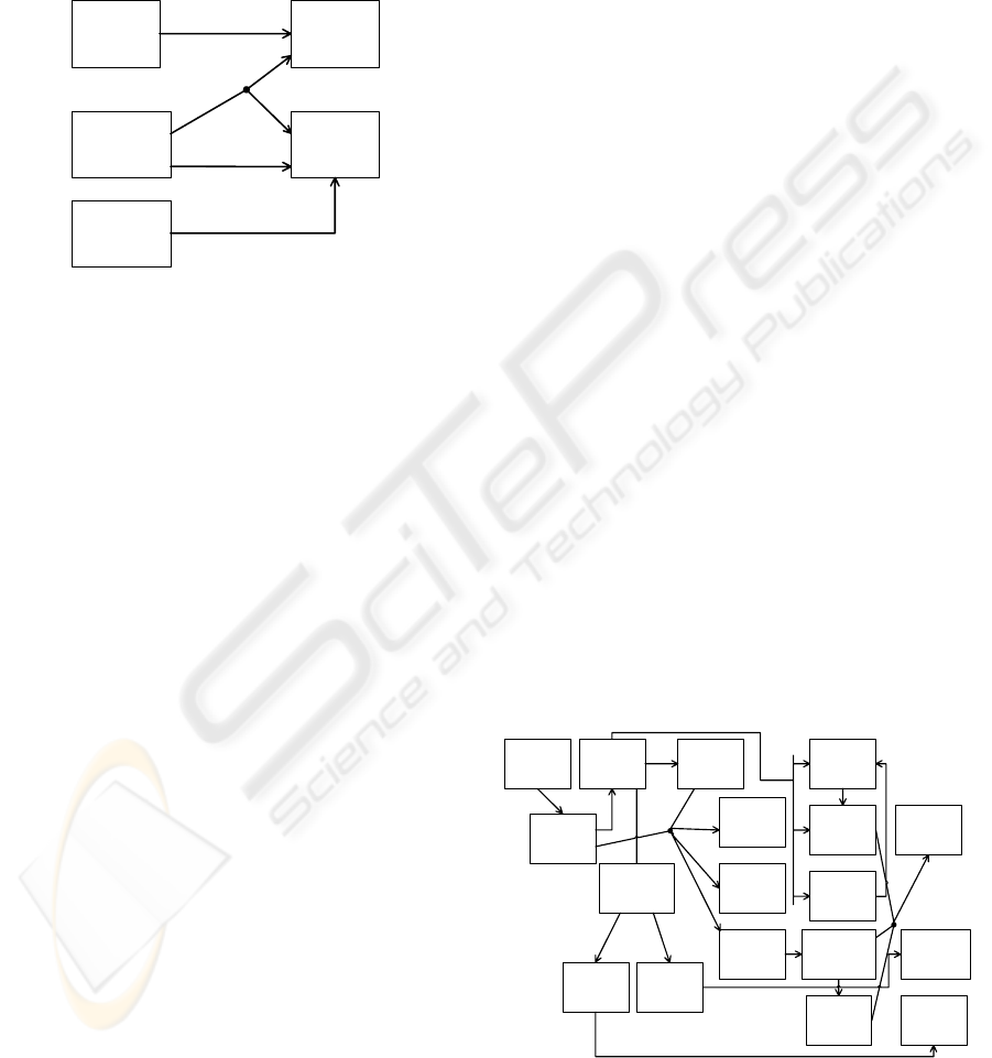
This word-description is depicted using the diagram
of concept transition in Figure 1. It can be seen, that
(one) entity transforms into (one) table. A
relationship can transform either into an attribute
(foreign key) or into a table with two or more
(according to the relationship’s level) foreign keys
(attributes). Attributes of entities and relationships
transform to attributes of tables.
The above described word-description is better
expressed by an algorithm, but a diagram better
depicts relationships and possibilities in the
GRADUAL MODELING OF INFORMATION SYSTEM - Model of Method Expressed as Transitions Between Concepts
539
transformation. This transformation can be done
automatically, because we know the correct
algorithm (see e.g. Godolla 2003). However, this is
not typical in methodologies of analysis and design.
We typically know the relations between concepts of
the methodology, but the concrete realisations of
these relations are chosen by analyst according to
their experience.
Figure 1: Concept transitions diagram for ER to physical
database model.
5 USAGE OF THE DIAGRAM OF
CONCEPT TRANSITION
With the method of IS analysis and design recorded
by the model of concept transition it is possible:
• To manage the development process – in
every moment it is possible to say, which
transformations the method allows (it is
possible for instance to create a CASE tool
capable of possible transformations offers).
We know which and how many elements
can originate in the next step of method.
• To check, whether the IS model matches
the used method. It is possible to control,
whether the element added to the model
matches the model. The CraftCASE
modelling tool supports such control (see
Craft.CASE ).
• Such record helps in performing some
transformations automatically or semi-
automatically. It is necessary to add the
algorithm that defines the transformation.
• To depict the process of a method – this
model can be used for defining relations in
a method and this can be used for instance
for easier understanding of relations inside
the method, for method teaching, etc.
• To control and improve methods – by
having all concepts and transitions defined,
it is possible to control, whether transition
between elements is not too rough (e.g. it
doesn’t transform directly to final classes,
in the extreme) or too fine.
6 BORM
BORM (Business Objects Relational Modelling) –
see Merunka at al 2003 is an object-oriented method
of IS analysis and design. It focuses on processes
running inside the modelled system, on their
revealing, analysis and following modelling. BORM
is an interactive method and is based on spiral model
of system design. One of the main rules in BORM is
depicting of its terms using sequential
transformations.
A process model is in BORM depicted as a set of
mutually communicating final automata. Those
automata represent business objects. After modelling
all processes using diagrams of processes a process
model is created. In this moment, a lot of BORM-
based projects end – BORM is often used just for
process analysis, e.g. for reengineering processes
purpose.
6.1 BORM and the Concept
Transformation
The basic idea of BORM methodology is based on
transitions between its concepts. So demonstrate
these principles is easy and straightforward (see
Figure 2).
Function
Scenario
Participant
Participant
Role
State
Transition
Action
Relationship
ISA
Association
Object
Class
Set
Method
Communicati
on
Data Flow
Composition
Inherition
1..*
1..*
1..*
0..*
1..*
0..*
1
1
1
0..*
0..*
0..*
1
1
1
1
1
1
1
1
0..1
1
0..*
1..*
0..*
1
1
0..*
0..*
0..*
1
1..*
1
Figure 2: Diagram of concept transitions of BORM
methodology.
Entity
Relationship
Table
Attribute
1
1
1
1
1
2..*
ERAttributte
1
1
1
ICEIS 2006 - INFORMATION SYSTEMS ANALYSIS AND SPECIFICATION
540
7 THE UNIFIED PROCESS
The Unified Software Development Process (USDP)
methodology, known better under its shortened
name Unified Process (UP) is one of many object-
oriented methodologies based upon the UML
language. This methodology comes directly from the
authors of UML (Booch, Jacobson, Rumbought –
see Jacobson at al. 1999) and is (together with its
derivatives – e.g. RUP) the most commonly used
iterative methodology.
7.1 UP and the Concepts Transition
To implement the ideas of sequential
transformations during the IS design for the UP
methodology is not as easy and straightforward as in
the case of BORM. One of the problems is that the
methodology itself consists of many alternative
methods. For the use of concept transitions we must
deal with individual methods and develop the overall
way through the methodology from them. In UP it is
the smartest to construct transition diagrams in each
work procedure.
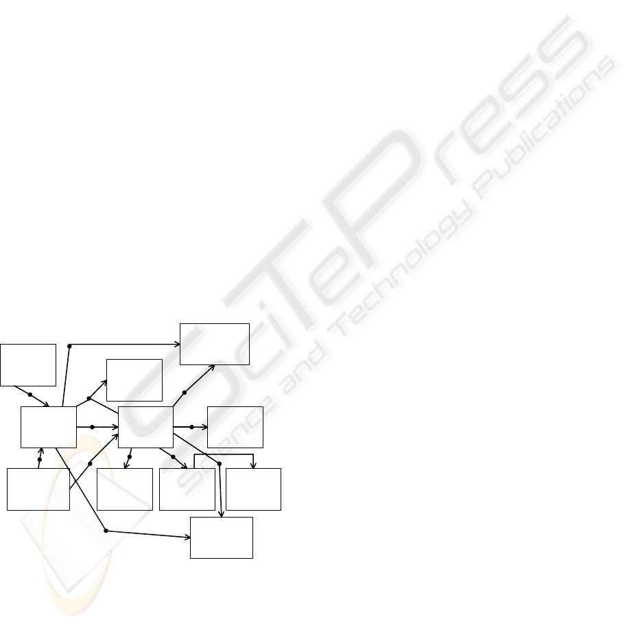
The next problem is that transitions between
concepts are not explicitly defined in the
methodology. The diagram of concept transition for
the work procedure of finding actors and use-cases
is in Figure 3.
Actor
Term
Definition
UseCase
Communica
tion
1
1
1
1
System
Boundary
1
1
1
Detailed
UseCase
Domain
Definition
Generalisation
0..*
0..*
0..*1..*
0..*
1
1
0..1
2..*
0..*
0..*
2..*
1
1
1
Include Extend
Extension
Point
22
0..* 0..*
10..*
1
1
Figure 3: Diagram of concept transitions of Use Case
model.
8 CONCLUSIONS
The model of concept transition allows to view
methods of IS analysis and design from a new
perspective. It gives an apparatus for formalizing
relations between concepts in the model and their
successiveness. The model helps gain a better
understanding of a method. The fact that relations
inside this method are well defined improves the
method’s manageability and the possibilities to
improve it.
During the IS development, by using the model of
concept transition we get several advantages. The
model can be used for managing the development
process, for control of the method usage and for
depicting the method’s process.
Existing CASE tools support some ideas of the
model of concept transitions, e.g. CraftCASE
modelling tool performs checks, whether the added
element conforms to the method. To further improve
the quality of analyst’s work, it would be a great
contribution to implement complex support for the
concept transitions model. A CASE tool could thus
better lead an analyst through the process of
analysis, give him hints, check and record his steps.
REFERENCES
Godolla, M., Lindow, A., 2003. Transforming Data Model
with UML. In Knowledge Transformation for
Semantic Web. IOS Press. Amsterdam.
Craft.CASE. http://www.craftcase.com
Merunka, V., Knott, R, Polak, J. 2003. The BORM
Methodology: a third generation fully object-oriented
methodology. In Knowledge-Based Systems. Elsevier
Science International. New York.
Liu. L, Roussev, R., Knott, R., Merunka, V. Polak, J at al.
2005. Management of the Object-Oriented
Development Process. – Part 15: BORM
Methodology. University of Akron. University of
Virgin Islands.
Picka. M. 2004. Guided development of Information
Systems. In Objekty 2004 – sborník příspěvků
devátého ročníku konference. Provozně-ekonomická
fakulta. Česká zemědělská univerzita. Praha.
Jacobson, I., Booch, G., Rumbaugh, J. 1999, The Unified
Software Development Process. Addisson Wesley
Profesional.
OMG. 2003. OMG Unified Modeling Language
Specification – version 1.5.
GRADUAL MODELING OF INFORMATION SYSTEM - Model of Method Expressed as Transitions Between Concepts
541
