
MINIMIZING THE COMPLEXITY OF DISTRIBUTED
TRANSACTIONS IN CORPORATE ARCHITECTURES WITH
THE USE OF ASYNCHRONOUS REPLICATION
S. R. Poltronieri, S. F. Paula, L. N. Rossi
Departamento de Informática da Reitoria – Universidade de São Paulo - Brasil
Rua da Reitoria, 109 - Bl K – 2
o
andar
Butantã, São Paulo - SP
ZIP CODE 05508-900
Keywords: Database, asynchronous replication, two-phase commit, distributed transactions.
Abstract: In software architectures commonly adopted by large corporations, the use of the “two-phase commit”
protocol for distributed transactions presents inconveniences such as code complexity, long response times
for the final user and need of an environment that allows complete simultaneity. We present here an
alternative strategy, based on asynchronous replication, successfully implemented since 1997 at the
University of São Paulo as infrastructure of integration for its corporate systems, which propitiates
distributed transactions in the context of databases deployed at several host servers.
1 INTRODUCTION
In an application with transactions distributed
through several databases, the “two-phase commit”
protocol is commonly used to guarantee the integrity
among the several databases. This strategy, however,
presents inconveniences: it makes the transactions
lengthy and its code more complex, burdening the
development teams and reducing the satisfaction of
the user in regard to the response times. In addition,
in order to complete a transaction, this strategy
requires that all the servers involved are
simultaneously available; namely, it depends on a
network infrastructure and on servers that present
high availability.
In this article we present an alternative strategy
of implementation using asynchronous replication of
data, which can face these problems, simplifying the
applications and integrating many databases in
different hosts. This strategy combines physical
project of the databases, the way the applications
connect to them and some features of a commercial
replication agent.
This solution is in use since 1997 for the
corporate systems of the University of São Paulo,
Brazil, to support the activities of the institution,
which today counts with 32 integrated databases.
2 TWO-PHASE COMMIT
VERSUS ASYNCHRONOUS
REPLICATION
The strategy “two-phase commit” is synchronous,
i.e., it implies that a transaction is only completed
after each one of the participants guarantees that the
transaction has been completed locally. If any of the
participants does not answer because the transaction
was not completed locally, or even due to
connectivity fault, all transaction is undone
(rollback). For instance, in scenery where a
transaction is distributed in five databases, it is
necessary to wait for the five databases to answer
affirmatively in order to consider the transaction
concluded. If, for any reason, the transaction needs
to be redistributed to a larger number of databases,
the transactional control needs to be recoded and it is
expected an increase in the response times. If one of
the databases is not accessible at the moment of the
transaction, it is undone in all the databases.
With the use of asynchronous replication data
changes do not happen at the same time. The
transaction is completed in a database and reapplied
to the others. If the transaction fails in one of the
databases, it does not necessarily fail in all the
323
R. Poltronieri S., F. Paula S. and N. Rossi L. (2006).
MINIMIZING THE COMPLEXITY OF DISTRIBUTED TRANSACTIONS IN CORPORATE ARCHITECTURES WITH THE USE OF ASYNCHRONOUS
REPLICATION.
In Proceedings of the Eighth International Conference on Enterprise Information Systems - DISI, pages 323-330
DOI: 10.5220/0002458103230330
Copyright
c
SciTePress

databases. Transactions are undone just in the site
where the fault occurs and they are submitted again
later on. This strategy always implies in a period of
latency for the data to be available (replication
latency). Updates delays will always occur in
databases that are inaccessible, but the other
databases will be updated after the time of latency.
Nevertheless, a measure of the latency can be
used by the application to limit risks for some
transactions. For example, an application can change
its behavior using an estimate of latency as an
advisory. If the latency is above a pre-defined
threshold, the application can reduce the values of a
loan or withdrawal.
3 IMPLEMENTATION AT THE
UNIVERSITY OF SÃO PAULO
Founded in 1934, the University of São Paulo (USP)
is the largest institution of higher education and
research in Brazil, and the third in size in Latin
America. With 746 courses taught in its teaching and
research units, 202 of which are undergraduate
courses attended by approximately 46,000 students,
and 487 are graduate courses (including 280 for
masters' and 264 for doctors' degrees). Its teaching
units are distributed among its eight campuses
spread in six cities.
To support its activities, USP has a complex
administrative infrastructure, most of which is
centralized in the city of São Paulo, but operations
are wide decentralized: each of the teaching units
has its administrative office and there are regional
headquarters hosted in each campus.
To confront this complexity, each business area
has its workflows implemented in control systems
for the business area (here called “application”).
However, since many of the flows pass through
more than one area, data integration is highly
needed.
The corporate data model of the University of
São Paulo was conceived to support this integration
and distribution of data and applications. This
logical model cover all businesses of the University
(Academic control for undergraduate and masters
degrees, Finances, Human Resources etc.) and it is
structured as a single relational model for all the
institution, having an extensive number of entities
and relationships. The physical implementation, due
to performance and availability considerations, is
distributed among several databases.
At the time of the initial implementation, the
hardware available at the University could not
operate satisfactorily all these databases from the
same server. The choice made, therefore, was to
distribute the databases among 4 servers, each one of
them concentrating on one of the main business
areas.
This scenery, if implemented in the traditional
“n-phase commit” way, would have implied in high
code complexity and transactional cost regarding
tables of common use to the applications, because,
in addition to repeating the same transaction in
several databases, guaranteeing in this way the
referential integrity of the model, each application
would have to establish connections with each one
of these databases for reading or recording
operations.
The physical implementation followed the
premises and definitions below:
3.1 Global Data Model
The downsizing process, that motivates systems
migration from mainframe to client server, started
with premise of a unique and integrated logical data
model, internally named “global data model”. This
logical abstraction was the answer to integration
problems with old mainframe data structure (apart
databases, one for each business area) such as
different id for same people, address or personal data
updated only in one database and incorrect in others,
difficulty in identify the same people data in each
database and so on.
The global data model contains unique logical
abstractions for each concept used in corporate
systems, independently which application uses it.
For example; all personal data, used by all
applications, is stored in a “PERSON” table.
People’s roles, such as student, graduate, professor
or faculty staff are stored in another table set. All
these tables (persons, roles, relationships) constitutes
a sub-model named “PERSON”. Organizational
unity information is stored in a sub-model named
“STRUCTURE”. Another example is applications
access, that is centralized and its control data is
represented in sub-model “USER”.
Although logical abstraction is unique to each
concept (PERSON, by way of example), its physical
implementation is distributed among several
databases. All databases that require PERSON for
read data, consistency or referential integrity have a
PERSON table replica. PERSON is primary in one
and only one database (see 3.5.1). Nowadays there
are PERSON table replicas in 28 databases.
ICEIS 2006 - DATABASES AND INFORMATION SYSTEMS INTEGRATION
324
The applications’ use of tables determine their
physical distribution and is better explained in
section 4.
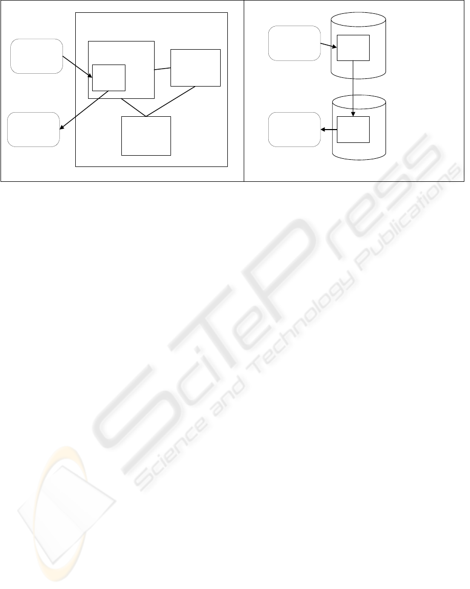
By way of example, logical and physical views
of PERSON table are showed schematically in
Figure 1.
3.2 Database Servers
The ambient is composed by 4 database servers.
3.3 Databases
The databases are grouped by business area and
distributed in the 4 servers. For example,
“undergraduate” and “graduate” databases lie in
same server. Each application has its preferential
database. “Human Resources” database is the one
that contains most of the tables and stored
procedures used by Human Resources management
application.
3.4 Replication Server
The replication agent chose for this implementation
is an autonomous and independent server that runs
in parallel mode to the database server (origin
database), scanning the current log of the databases
and writing all committed transactions executed at
the databases in a replication proprietary queue. This
queue is used to distribute data changes to other sites
(destination databases). The transactions are
reapplied in the destination databases in the same
order that occurred in the origin database, doing
another transaction at the destination databases. This
strategy preserves chronological events in all
databases. The replication agent guarantees that all
transactions on the replication queue are completed
on the destination databases, even if some of the
destinations are unavailable for a time. The pending
transaction lies in the queue until the destination
becomes available. Therefore, the replication latency
between the sites is very short if the environment has
high availability.
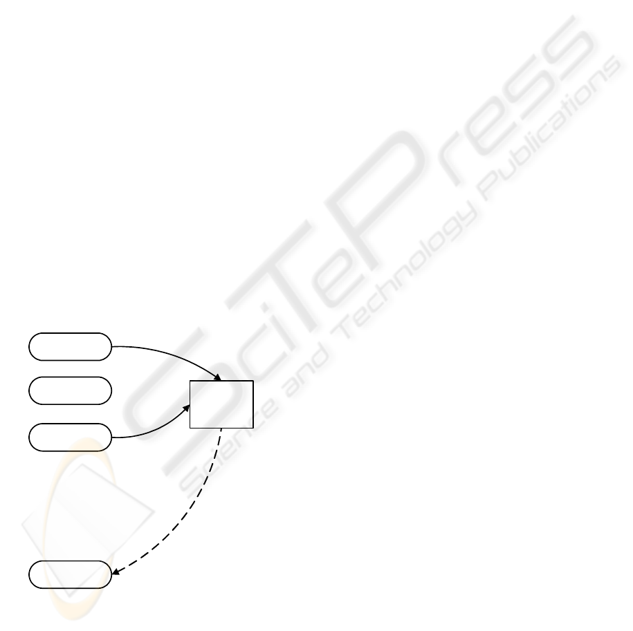
An instance of replication agent in each site
coordinates the data replication communicating with
replications agents in other sites. Thus, the main
tasks of a replication agent are to receive data
transactions from databases and distribute them to
sites with subscriptions for the data and to receive
transactions from other replication agents and apply
them to local databases, as showed schematically in
Figure 2.
Consider the tables T1 (primary in database DB1
and replicated in database DB2) and T2 (primary in
database DB2 and replicated in database DB1). The
replication process steps are:
1. Changes in table T1 are registered in
database DB1 log
2. Replication agent R1 reads data
transaction from DB1 log
3. Transaction is sent to replication agent R2
4. Replication agent R2 apply locally in
database DB2 the received transaction,
replicating the changes in table T1
This process is symmetric for table T2, and
occurs in analogue way, represented by steps 5 to 8
and dotted lines.
Global data model
Human
Resource
application
Academic
control
application
PERSON
table
PERSON
sub-model
STRUCTURE
sub-model
USER
sub-model
...
Logical view
Academic
control
database
Human
Resource
database
Human
Resource
application
Academic
control
application
PERSON
table
PERSON
table
replication
Physical view
Figure 1: Global data model - logical and physical views.
MINIMIZING THE COMPLEXITY OF DISTRIBUTED TRANSACTIONS IN CORPORATE ARCHITECTURES WITH
THE USE OF ASYNCHRONOUS REPLICATION
325

3.5 Tables
3.5.1 Primary and Replicated Tables
Regardless of the application that is manipulating
the data, all the transactions of data manipulation
(insert, update and delete) on a table should
necessarily occur in a single database. The motto of
this strategy is “write once here, read anytime,
anywhere”. This fundamental premise implies that
each table is primary in only one site. Other sites
contain a replica of the table (replicated table) and
the applications only read data from replicated
tables.
The process is summed up in Figure 3:
1. Application A1 transacts in database DB1
updating data on some table
2. Replication agent R1 receive data
transaction
3. Transaction is sent to other replication
agents (R2 and R3)
4. These agents apply locally the received
transactions (in DB2 and DB3
respectively)
5. Replicated data (updated!) in DB2 and
DB3 is available to applications A2 and
A3
DB1
R1
writeA1
A2
A3
DB2
DB3
read
read
1 2
3
4
R2
R3
4
5
5
3
Figure 3: Database access and replication process.
R1
DB1
T1 T3T2
DB2
T1 T3T2
DB3
T1 T3T2
R2 R3
Figure 4: Scalable architecture.
A1
A2
A3
.
.
.
.
An
read,write
no action
no action
no action
Only ONE
application access
the table
Table
Analyzed
Figure 5: Unique table.
R1
1
3
L
O
G
DB1
2
4
7
8
T2
T1
R2
5
L
O
G
DB2
6
T1
T2
Figure 2: Basic structure of a replication system.
ICEIS 2006 - DATABASES AND INFORMATION SYSTEMS INTEGRATION
326
Actually, this solution has properties of
symmetry, is scalable and presents emergent
behavior. If table T1 is primary in database DB1,
table T2 is primary in DB2 and table T3 is primary
in DB3 and all tables are mutually replicated, we can
construct a very complex architecture based in this
simple mechanism (Figure 4).
3.5.2 Unique Tables
A table which residence was defined in only one
database in the whole ambient is called “unique
table”. Unique tables are commonly accessed by
only one application (Figure 5).
3.5.3 Common Tables
Some tables, used by several applications, such as
tables with data of the organizational structure, of
people and their roles and relationship with the
institution (students, faculty employees, suppliers,
etc.), end up residing in more than one database and
even in different servers.
A table which residence was defined in more
than one database in the whole ambient is called
“common table” (Figure 6). In general, all databases
end up possessing a group of common tables.
4 STRATEGY OF SITE
ELECTION FOR PRIMARY
AND REPLICATED TABLES
The tables are usually grouped by application. For
each application, a main database is chosen, that is, a
database in which the group of tables used by the
application will reside. The relationships are
respected in this grouping, guaranteeing the
implementation of the referential integrity through
the migration of keys.
The business and its respective applications
maintain a hierarchy of responsibility on the data.
For instance, the students’ personal data are the
responsibility of the academic systems. If a person is
at the same time student and faculty employee, the
responsibility of that person’s data becomes of the
human resources system.
For each common table, it is analyzed which
application requires more transaction on it, that is,
which applications will accomplish more frequently
operations of data manipulation (insert, update and
delete).
It is elected as primary database of the table the
one that is the “preferential” database of the
application that is more demanding of operation on
the table.
The operations of data manipulation on this table
(insert, update and delete) will be made by the
applications only in the primary database. The other
sites (replicated sites) will contain only a replica of
this table, for reading or referential integrity
purposes. A “Student” table will lie in “Academic”
database, where its data are changed and updated.
The Library application will use “Student” only to
read students personal data, such as address to get
back a lent book.
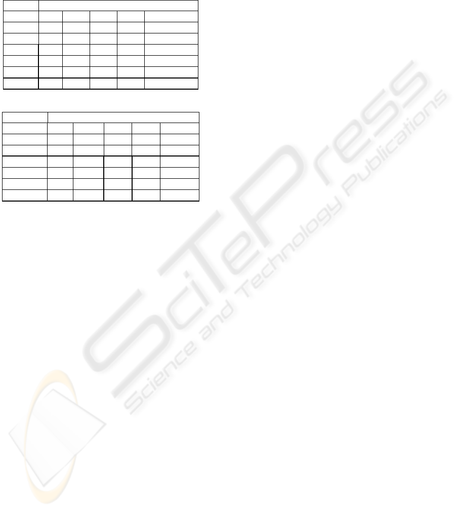
The ways that each table are accessed by the
several applications (Figures 5 and 6) are analyzed
and the use – r=read, w=write (update, delete, insert)
– is mapped (sample in Table 1).
Applying the concept of preferential database of
the application, the primary site (P), the replicated
sites (R) and the site in which the table is unique (U)
are defined for each of the common tables (sample
in Table 2).
If a table is used for more than one application,
the primary site of the table is chosen as the
preferential database of the application that:
1. requires more operations of data manipulation
on the table or
A1
A2
A3
.
.
.
.
An
read
Table
Analyzed
No action
read, write
read, write
Figure 6: Common table.
MINIMIZING THE COMPLEXITY OF DISTRIBUTED TRANSACTIONS IN CORPORATE ARCHITECTURES WITH
THE USE OF ASYNCHRONOUS REPLICATION
327
2. posses more referenced tables for the table in
question or
3. requires minor latency of data update
Table 1 : Access of the Tables by the Applications.
Applications
Table A1 A2 A3 .. An
T1 r,w r r .. -
T2 r - r .. r
T3 - r - .. r
T4 r r r .. r
...
Tn - r,w - .. -
Table 2 : Tables and their respective sites.
Databases
Table DB1 DB2 DB3 .. . DBn
T1 P R R .. . -
T2 R - R .. R
T3 - R - .. R
T4 R R R .. R
...
Tn - U - .. -
5 STRATEGY OF THE
TRANSACTIONS IN EACH
APPLICATION
The applications are then coded according to the
architecture described above, establishing in a
selective way connections with the databases for the
accomplishment of the operations of data
manipulation (select, insert, update and delete).
5.1 Insert and Update
All transactions of any application that involve
insert or update shall be accomplished only in the
database in which the common table is elected as
primary or unique.
5.2 Select
If the application only reads from some common
table, this can be accomplished in the own database
where the application is connected, since the table is
already there as replicated table.
5.3 Delete
In a similar way to the insert and update operations,
the transaction shall be accomplished only in the
primary site of the table, however, in this case, it is
necessary a verification and the previous removal of
the data from the referenced tables in all the
replicated sites before the removal is made in the
primary site so that the referential integrity of the
model is maintained among all the databases.
6 LATENCY MEASURE
The replication agent used has a graphic monitor
tool that shows information about replication
process between two databases. Typically it shows
how latency and commit age change with time.
Latency shows the time it takes to distribute an
update from a origin database and commit it to a
destination database. Latency includes replication
agent internal queue processing, network overhead
and replication agents (origin and destination)
processing. It is defined as the difference between
the time when the transaction was committed to
database destination and when the transaction was
committed on the origin database, considering time
zones difference:
latency = destination_commit – (origin_commit –
time_zone_dif)
Commit age shows the amount of time that has
passed since the last update was committed to the
origin database. A continuous increase in commit
age indicates that no new transactions have been
received. When this occurs, the graph shows the last
latency for which transactions were actually
committed and not the current latency.
A sample of graph provided by this tool is
showed in Figure 7. Latency and commit age are
measured in seconds. The sample was caught in a
interval of regular database use.
When processing small transactions, latency and
commit age are small because the replication agent
processes the transactions quickly. Large
transactions take longer for the replication agent to
commit and the number of transactions in queue
increases. If other transactions arrived in queue, the
latency stays constant and the commit age starts to
increase.
ICEIS 2006 - DATABASES AND INFORMATION SYSTEMS INTEGRATION
328

We can observe from graph that the latency is
always lower than 5 seconds, with average time of 3
seconds. Plateaus occur after the arrival of a single
large transaction spaced in time. Valleys occur after
a small transaction, and latency constant value with
maximum committed age (actually increasing, but
not showed in graph) means no transaction and the
latency value is the last latency value measured.
7 CONCLUSIONS AND FUTURE
WORKS
The strategy here presented has been implemented in
the corporate systems of the University of São Paulo
since 1997, initially with six databases. The first
applications to use this architecture were client-
server two-tier. The natural increase of the IT
participation in the business of the institution raised
this initial group to the 32 databases currently in use,
occupying 300 Gbytes of data, with more than 1,500
logic tables, implemented physically in more than
4,500 tables.
Even in the complex environment as the one
described here, the latency presented is very low
and, in practice, it is possible to say that the
integration of data is online, that is, data that is
handled by any of the applications are made
immediately available in all the environment for use
by other applications and users.
In addition, due to easiness of handling and
configuration of the replication agent, the
operational management is surprisingly simple,
requiring part-time work of only one IT staff
member.
From its conception, the solution has shown to
be absolutely robust and scalable. In the eight years
since its implementation, the model has supported
the growth of the number of modules of the
applications as well as the appearance of new
systems and, with the coming of applications in the
Web, it has shown to be extremely advantageous,
facilitating the fast and easy implementation of
several functionalities related, for instance, to safety
and performance, since the public consultations
made available through the Internet are
accomplished in databases that possess only
replicated tables for consultation, isolated from the
transactional ambient (OLTP).
Given the success of this strategy, we are
accomplishing studies for its use in the integration of
purchased software (with the proprietary data
model) to the corporate model of the institution.
Figure 7: Latency and commit age graph.
MINIMIZING THE COMPLEXITY OF DISTRIBUTED TRANSACTIONS IN CORPORATE ARCHITECTURES WITH
THE USE OF ASYNCHRONOUS REPLICATION
329

REFERENCES
Ladin, R., Liskov, B., Shrira, L., and Ghemawat, S. 1992.
Providing high availability using lazy replication.
ACM Transactions on Computer Systems 10, 4
(Nov.), 360-391.
Sybase Replication Server Design Guide, 1995,
Replication Server Technical Publications - Sybase,
Inc., Doc ID 32580-01-1100-01
Sybase Replication Server Administration Guide, 1995,
Replication Server Technical Publications - Sybase,
Inc, Doc ID 32511-01-1100-02
Sybase Replication Server Manager User’s Guide for
Microsoft Windows, 1996, Systems Management
Products Technical Publications - Sybase, Inc, Doc ID
32002-01-1100-01
ICEIS 2006 - DATABASES AND INFORMATION SYSTEMS INTEGRATION
330
