
CSPJade: Architectural Driven Development of Complex
Embedded System Software Using a CSP Paradigm
Based Generation Tool Code
Agustín A. Escámez, Kawthar Bengazhi, Juan A. Holgado, Manuel I. Capel
Dpto. De Lenguajes y Sistemas. ETS Ingeniería Informática. University of Granada, Spain
Abstract: A code generation tool for the development of control system
software based on an architectural view of distributed real-time systems as a set
of communicating parallel processes is presented. Firstly, we obtain a complete
system specification by using the CSP+T process algebra. Secondly, an
architectural design of the entire system under modeling is performed using the
CSPJade graphical tool; once a model of the system is achieved in the CSPJade
framework, an implementation in Java can be automatically generated by using
the JSCP library. CSPJade defines a graphical abstract model of processes
similar to the semantic of CSP+T, so a translation of modeling entities into
CSP+T processes and vice-versa is easy to achieve and becomes less error
prone. CSPJade allows the designer to deploy a set of reusable software
components which are stored in two XML structures, the java project model
(JPM) and the java container model (JPM).
1 Introduction
The specification of user requirements is considered a key phase of the development
cycle of software systems. To achieve the system specification task goals, a
comprehensive and accurate description of functional and non-functional
requirements must be provided. A new framework together with a structured
graphical language is proposed here to obtain a specification of behavioral and
temporal requirements of real-time systems. In addition, the modeling entities can be
translated into correct syntactical terms of a process algebra derived from CSP+T [1].
Many semi-formal system requirement specification and analysis notations,
(SA/RT, CPN, CTPN, UML/RT, etc.) lack of predictable analysis entities when they
are applied to the development of real-time systems; whereby these modeling
languages make impossible to perform any verification or temporal analysis of the
system model. As consequence, timing and dependability requirement analysis of
real-time distributed control systems is usually performed by the development team
after completely developing a system prototype in the industry. As a consequence,
many prototypes result discarded, especially first prototypes, before obtaining an
acceptable version of the final system. In addition, system validation only based on
testing prototypes is not a good Software Engineering practice, since several of these
A. Escámez A., Bengazhi K., A. Holgado J. and I. Capel M. (2006).
CSPJade: Architectural Driven Development of Complex Embedded System Software Using a CSP Paradigm Based Generation Tool Code.
In Proceedings of the 4th International Workshop on Modelling, Simulation, Verification and Validation of Enterprise Information Systems, pages
128-133
DOI: 10.5220/0002463701280133
Copyright
c
SciTePress
usually need to be built and discarded before obtaining a correct implementation of
the final system, which increases development costs and delays its delivery date.
A Process Algebra (PA) is an algebraic approach for studying concurrent systems
made of parallel communicating or synchronizing processes. Differently from other
formal design languages, PAs are compositional. In this work we investigate how to
carry out the development of a graphical framework for supporting a PA formal
specification language, by providing a hierarchical, visually oriented, representation
of processes and channels, which allows us: (a) to abstract a group of processes into a
structured one, (b) to zoom inside a structured process in order to declare and (c) to
manage channel connection definition between component processes in a
comprehensive way. Our claim is that this tool can be used by analysts and developers
without a deep knowledge of mathematics and logics to derive a provably correct
system model.
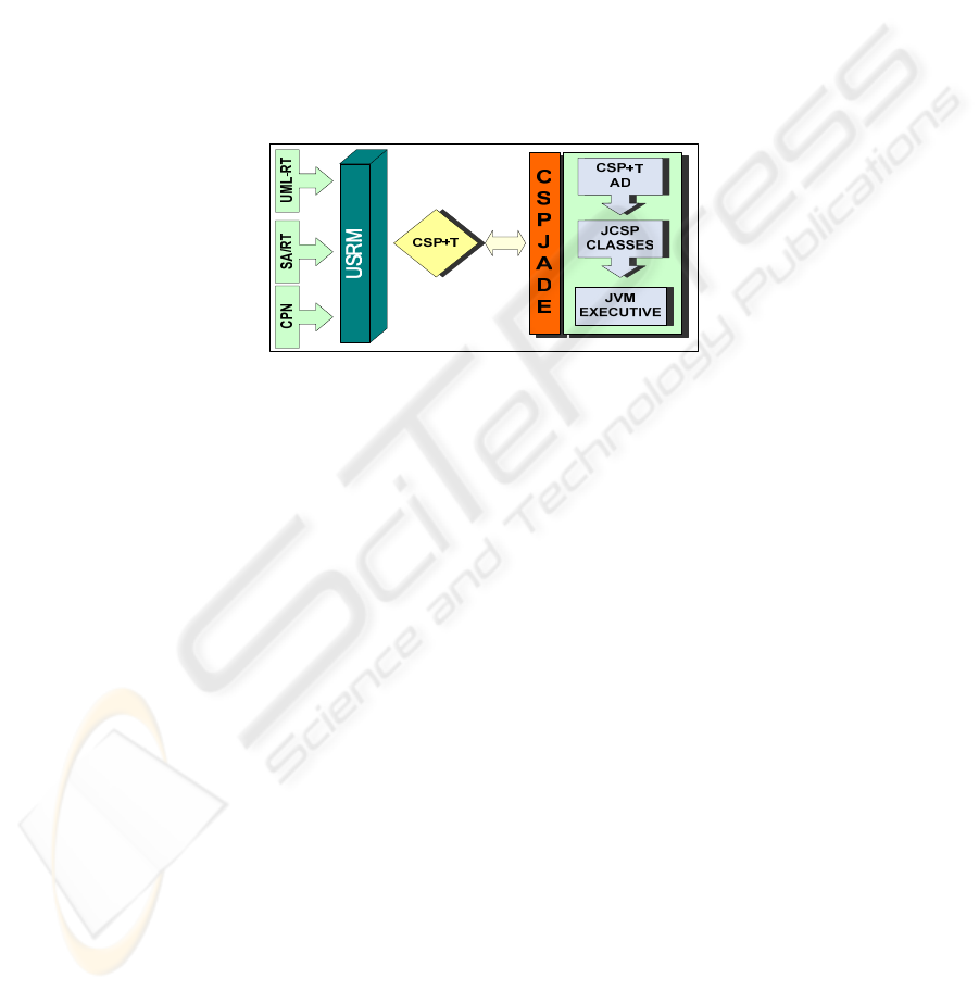
Fig. 1. Methodology proposed by [2] Capel et al.
The complete roadmap to obtain a complete system specification following our
method is given in Fig.1. Starting from an initial user requirement specification model
(URSM), a detailed system design by using CSP+T PA notation is obtained by
following a systematic transformation [2]. The procedure allows us to model real-time
processes including the specification of their timing requirements Finally, by
employing the graphical software tool CSPJade, we can perform a design automation
of distributed embedded real-time control systems and the complete development
process can be fully implemented in Java with the support of CTJ [3] or JCSP [4]
libraries.
2 Background
Graphical notations for modelling and building software systems have been used in
different stages of the development process of software, in special notations based on
UML [5,6]. Some of them are capable of a “formal” reasoning of a URSM, as to
mention Statecharts, with its formal official [7] semantics supported by the Statemate
tool, the Unified Modelling Language (UML), a semi-formal language for visualising
different systems from different perspectives, and which possesses different profiles
[8] that can be used for developing some kind of specific systems as embedded or
real-time systems in specific languages.
129
Pezzè et al. [9] has focused on providing a formal semantics for Structured
Analysis style diagrams. Their work revealed that the numerous different
interpretations of data flow diagrams can be structured and classified.
Dong et al. [10] considered visualising Timed Communicating Object-Z (TCOZ)
specifications on the web by using XML/XML and UML diagrams as projected
views. The automated reasoning of system properties within the design phase of these
systems can be facilitated by using the proposed graphical tool.
3 CSPJade Definition
CSPJade is a graphical tool implemented in Java that allows us to perform a
structured analysis of complex systems described as CSP+T specifications assisted by
a graphical language.
package ProductionCell;
import jcsp.lang.*;
public class FeedBeltControl im plem ents CSProcess {
private final ChannelInput cinBeginB lankRob3;
private final ChannelOutput coutBeginFeedBeltEm pty;
private final ChannelOutput coutEndFeedBeltFull;
private final ChannelInput cinStateBeginBelt;
private final ChannelInput cinStateEndBelt;
private final ChannelOutput
coutBeginBarrierFeedBeltReady;
private final ChannelO utput
coutEndBarrierFeedBeltReady;
private final ChannelO utput coutM oveMotor;
private final ChannelO utput coutEndFeedBeltTim e;
public FeedBeltC ontrol(ChannelInput
cinB eginBlankR ob3,
ChannelO utput coutB eginFeedBeltEm pty,
ChannelO utput coutEndFeedBeltFull,
ChannelInput cinStateBeginB elt,
ChannelInput cinStateEndBelt,
ChannelO utput
coutBeginBarrierFeedBeltR eady,
ChannelO utput
coutEndBarrierFeedBeltReady,
ChannelO utput coutM oveM otor,
ChannelO utput coutEndFeedBeltTim e) {
this.cinBeginBlankRob3 = cinB eginBlankRob3;
this.coutBeginFeedBeltEm pty =
coutBeginFeedBeltEmpty;
this.coutEndFeedBeltFull = coutEndFeedBeltFull;
th is .cin S tate B e g inB elt = cin S tateB eg in B e lt;
……..
}
FeedBeltControl = Feed_Belt_Movem ent\{start}
||In itF e e d B e lt
||W aitingBlank\ {BeginFeedBelt_Full_True, B eginFeedBelt_Tim e}
|| TakingOut_Rob3\{BeginFeedBelttim e}
|| M oving_Feed_Belt\{EndFeedBelt_Full_true }
|| Unloading_Blank\{EnFeedBelt_Full_false,
W a itin g _b lan k !re s u m e(), W a itin g B a ln k ? re s u m e (),
Sync !EndFeedBeltCleraded (),
Sync?EndFeedBeltCleraded()}
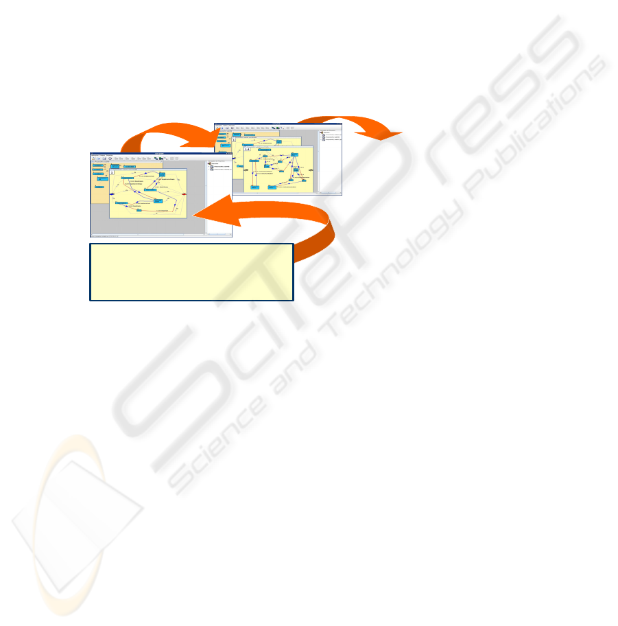
Fig. 2. Stages to achieve code generation.
An implementation of the system can be automatically generated in Java with the aid
of the JCSP library as we presented recently in [11].
A model in CSPJade, i.e. Figure 3 is an n-tree hierarchical structure of graphs
constituted by two main modelling elements: Processes and Channels. A process
represents an independent self-contained entity which interacts with its environment
through the channels. A channel is the entity that represents the connection of two
processes in one specific direction. With these elements a static architectural model of
the system can be built as a set of nested “views”. Each of these contains the
information relevant to the processes inside the view.
130
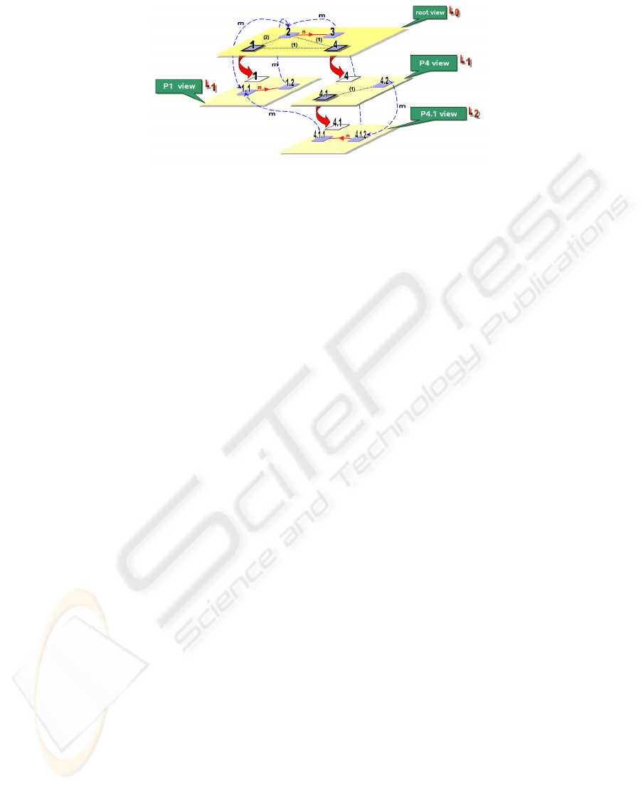
Fig. 3. Hierarchical abstract representation of a system in CSPJade.
The Channel entity creation is straightforward, but the global establishment of a
Process entity implies the consecution of two objectives: firstly, the graphical
connections of the Process through the channels must be done, obtaining by
composition of these the static architectural diagram of the system. Secondly the
behavioral part of the Process must be defined, as a function of the data that receives
through its input channels and sends through its output ones. In Figure 2 we show a
schematic view of a nested set of Processes and Channels..
3.1 Analysing Reusability Aspects
Our graphical tool makes use of XML technologies [12,13] to gain interoperability in
a near future with other formal tools for real-time systems, i.e. FDR, and reusability is
guaranteed by means of the deployment of the XML structures, namely JPM and
JCM, with the aid of the JDOM library [14]. JPM stands for Java Project Model,
which is a repository usually consisting of one file and a specific structure to store the
information model. The JPM structure contains the graphical and executive aspects of
a project, which encapsulate the underlying logical structure of the model. JCM
stands for Java Component Model, its structure is based on a specific Process and it is
a reusable unit of a system with a precise static and functional description of the
nested elements that it contains.
4 Case of Study: Stages to Achieve Code Generation in the
FeedBelt Control
The Feed Belt Control is a main part of the production cell, which is a well-known
realistic manufacturing industry oriented problem [15], where safety requirements
regarding the fulfilment of timing-constraints by the different concurrent movements
of the cell components (robot arms, conveyor belts, press, etc.) are of paramount
importance in order to have a useful design of the target system. The proposed
configuration of the production cell as well as the CSP+T specification that can be
seen in the lower left corner of Figure 2 is well detailed in [11].
131

We can summarize the steps, graphically represented in Fig. 2 as follows:
1. A CSP+T specification of the system must be obtained
2. The static architectural design of the system is done, by creating the nested set of
processes and channels, and specifying the behavioral part of the processes as a
function of the input/output data carried by the channels
3. Each executive part of a Process entity analyze its graphical structure, the data that
carries its channels and performs the necessary computations to deliver the
executable Java code
5 Conclusions and Future Work
Up to now a first version of our graphical editor has been built which allows obtaining
an architectural diagram of the system, and the code generation module will be
available in a short term, as well as other features that are discussed next.
Because we share a common interest with the work conducted by Jovanovic et al
[16], and Hilderink [17] much of the following features planned to be added to our
graphical tool in future releases are common to those presented by them:
− A coherent, complete and syntactically correct notation needs to be included in our
tool, Brooke, Jovanovic and Hilderink notations are been carefully examined for
this purpose.
− The temporal aspects of a communication line must be implemented to allow the
design and analysis of real-time systems of a consistent way with the CSP+T
process algebra.
− A GUI for allowing the implementation of new functionality of a process is, at this
time, being developed. The functionality of the process will be saved in a XML
structure through an adequate DTD or XML Schema.
− A temporal analysis module must be developed to perform scheduling analysis of
complex designs of real-time systems, so that we can derive a provably correct and
complete design previously to the implementation of any system prototype.
Finally, we hope that our graphical tool will help to expand the use of CSP by
helping designers and developers in the task of concurrent system design and
application programming, mainly in the development of real-time and embedded
system.
References
1. John J.Zic, “Timed constrained buffer specifications in CSP + T and timed CSP”. ACM
Transaction on Programming Languages and Systems, vol.16, 6, 1994, pp. 1661-1674
2. Kawthar Benghazi and Manuel Capel. Combining the description features of UML/RT and
the CSP+T specification applied to a complex design of real-time systems. In 5thIEC05,
Prague. Czech Republic, August 2005.
3. G.H. Hilderink. The CTJ (Communicating Threads in Java) home page.
http://www.rt.el.utwente.nl/javapp , 2000
132

4. P.Welch, “Process Oriented Design for Java: Concurrency for All”, in Computational
Science – ICCS 2002, Lecture Notes in Computer Science, 2330, Springer-Verlag, April
2002 (Keynote Tutorial), pp. 687-687.
5. G. Booch, J. Rumbaugh, and I. Jacobson, “The Unified Modeling Language User Guide”,
Addison-Wesley, Reading, Massachusetts, USA, 1999.
6. Phillip J. Brooke and Richard F. Paige. The design of a tool-supported graphical notation
for timed CSP. In IFM 2002: Proceedings of the Third International Conference on
Integrated Formal Methods, pages 299318, London, UK, 2002. Springer-Verlag.
7. D. Harel and A. Naamad, “The statemate semantics of Statecharts”. ACM Transactions of
Software Engineering and Methodology, vol.5, 4, October 1996, pp.293-333.
8. B. Selic, “Using UML for modeling complex real-time systems”. Lecture Notes in
Computer Science, 1474, Springer-Verlag, 1998, pp.250–260
9. Baressi, L., Pezzè, M., 1998. Towards Formalising Structural Analysis. ACM Transactions
on Software Engineering and Methodology, 7, 1, pp.80-107
10. Brendan Mahony and Jin Song Dong. Timed Communicating Object Z. IEEE Transactions
on Software Engineering, 26, 2, pp.150-177, 2000.
11. Juan A. Holgado, Agustín Escámez, and Manuel I. Capel. From CSP+T specification to
java implementation: The production cell case study. In CEDI 2005: I Congreso Español de
informática, Granada, Spain, September 2005.
12. Upgrade. XML (eXtensible Markup Language): The ASCII of the 21st century? . Vol. III,
Issue no. 4, August 2002
13. Upgrade. XML Today.Vol. VI, Issue no. 1, February 2005
14. Abhijit Belapurkar. Jdom home page, 2005. http://www.jdom.org.
15. Claus Lewerentz and Thomas Lindner, editors. Formal Development of Reactive Systems -
Case Study Production Cell, volume 891 of Lecture Notes in Computer Science, London,
UK, January 1995. Springer-Verlag.
16. Dusko S. Jovanovic, Bojan Orlic, Geert K. Liet, and Jan F. GCSP: A graphical tool for
designing CSP systems. In Communicating Porcess Architectures 2004, pp.233-251,
Oxfors, U.K., 2004. IOS Press.
17. G. H. Hilderink. Graphical modelling 'language for specifying concurrency based on CSP.
IEE Proceedings, Vol 150, No 2, April 2003
133
