
A System Dynamics Approach for Airport Terminal
Performance Evaluation
Ioanna E. Manataki
1
and Konstantinos G. Zografos
1
1
Athens University of Economics & Business, Department of Management Science and
Technology, TRANsportation Systems & LOGistics Laboratory (TRANSLOG),
Evelpidon 47A & Lefkados 33, 113 62 Athens, Greece
Abstract. Performance modelling of highly complex large-scale systems con-
stitutes a challenging task. The airport terminal is a highly dynamic and sto-
chastic system with a large number of entities and activities involved. In this
context, developing models/tools for assessing and monitoring airport terminal
performance with respect to various measures of effectiveness is critical for ef-
fective decision-making in the field of airport operations planning, design and
management. The objective of this paper is to present the conceptual frame-
work for the development of a generic, yet flexible tool for the analysis and
evaluation of airport terminal performance. For the development of the tool, a
hierarchical model structure is adopted, which enables a module-based model-
ling approach, and System Dynamics is used as the theoretical basis.
1 Introduction
Performance modelling of highly complex large-scale systems constitutes a challeng-
ing task. The airport terminal exhibits dynamic behaviour in space and time and is
characterized as a highly complex system, since it involves a large number of entities,
a large variety of types of services, complex interrelations between processes, vari-
ability and stochastic events. Airport stakeholders and policy makers involved in
airport strategic planning and operations face challenging decision-making problems
with significant trade-off’s between resource utilisation and customer service fulfill-
ment [9]. To address these requirements, several models/tools have been developed to
analyze and model airport terminal operations [1], [3], [6], [9] but no single model
provides the capability of fully addressing the peculiarities of airport terminal do-
main, and being easily customisable to local conditions of any airport. Currently
available models are either too macroscopic, failing thus to capture the complexity of
airport terminal processes, or models of specific airports. Consequently, there is an
urgent need for adopting a new approach to develop a generic tool for modeling air-
port terminal operations, that will also provide the flexibility to adapt to the specific
characteristics and conditions of any airport terminal in a user-friendly way. The
objective of this paper is to present the conceptual framework for the development of
a generic, yet flexible and easily customizable tool for the analysis and evaluation of
airport terminal performance.
E. Manataki I. and G. Zografos K. (2006).
A System Dynamics Approach for Airport Terminal Performance Evaluation.
In Proceedings of the 4th International Workshop on Modelling, Simulation, Verification and Validation of Enterprise Information Systems, pages
206-209
DOI: 10.5220/0002479202060209
Copyright
c
SciTePress
2 Airport Terminal Domain Modeling Approach
The conceptual framework developed is based on: i) domain modeling, to address the
need for having a generic way of analysing the requirements of any airport terminal,
ii) simulation and System Dynamics (SD), since they provide a framework to under-
stand the operations of complex dynamic systems and view the impacts of any deci-
sion on the entire system [5], [7], and iii) a module-based modeling approach, to
address the design requirement for flexibility, which in turn influenced the adoption
of a hierarchical structure for the model. The tool is structured into two hierarchical
levels: the first level of the hierarchy reflects the airport terminal system decomposi-
tion into a set of airport functional areas; at the second level, the functional areas are
decomposed into service facilities (modules) of the airport terminal, e.g. the check-in
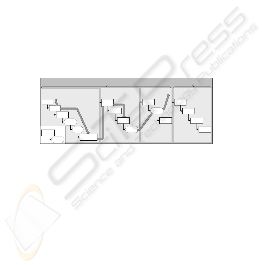
facility. Figure 1 provides a total insight into the model architecture, its hierarchical
structure, and the relationship between hierarchical levels. In the same figure, an
example of a departing passenger flow throughout the various facilities of the airport
terminal is graphically illustrated (with the grey arrows).
AIRPORT TERMINAL MODEL
Arrivals’ Controlled Airport
Functional Area
Controlled Airport Functional
Area
Unrestricted Airport Functional Area
Ticketing
Check In
Ancillary
Facilities
Waiting
Lounges
Arrival
Halls
Gates Airport Functional
Area
Boarding
Arriving at the terminal
Boarding Pass
/ Ticket Control
Security
Screening
Passport
Control
Ancillary
Facilities
Waiting
Lounges
Ancillary
Facilities
Gate
Lounges
Passport
Control
Customs
Ancillary
Facilities
Baggage
Claim
Passport
Control
Processing
Facility
Holding
Facility
Diagram Notation
Flow
Facility
Departures Arrivals
Fig. 1. Model Hierarchical Structure.
The modeling process of the tool was based on the meta-model depicted in Figure
2. The facilities modeling process is based on a general typology of the facilities
involved into processing, holding, and flow facilities [1], [2]. In processing facilities,
processes providing some type of services, e.g. check-in, security check, etc., to a
variety of customer groups take place; holding facilities provide passengers with the
required space to wait over a period of time; and flow facilities are used to accommo-
date the movement of passengers between the various holding and processing facili-
ties of an airport terminal [2]. Overall demand for services is determined by the air-
port flight schedule, which determines arrival and departure patterns of the various
customer groups at the terminal. As customer groups get processed through the sys-
tem, the demand for downstream facilities is determined by the outflow of preceding
facilities. The capacity of a facility is expressed though: i) the number of passengers
served per unit time, for processing facilities, ii) the maximum number of passengers
accumulated per unit area, for holding facilities, and iii) the maximum customers’
flow through a particular flow facility per unit time, for flow facilities.
207
CUSTOMER PROCESS
SERVICE FACILITY RESOURCE
SERVICE PROVIDER
PROCESSING FACILITY HOLDING FACILITY FLOW FACILITYSERVICE CHANNEL
managed_by
uses
1..n
supports 1..n
operated_using
1..n
allocated_by
supported_by1..n
Fig. 2. The Simulation Metamodel (modified after [2]).
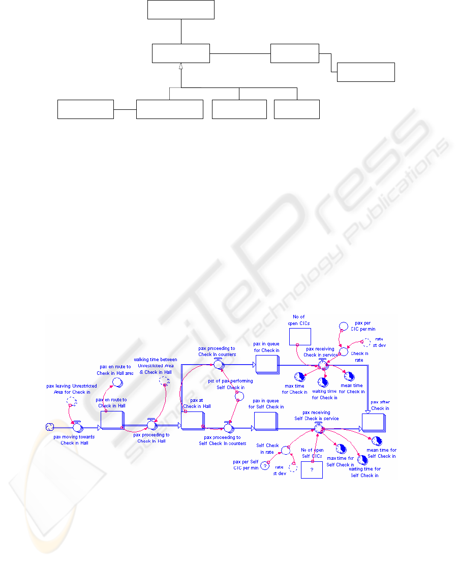
The services offered by the various facilities are represented by stocks (rectangles)
and flows (pipes) and are controlled in terms of information feedback and process
parameters (converters). Stocks represent the state of a process, e.g. passenger accu-
mulation in queue for ticket counters, whereas flows the rate of change of this state,
which is determined by variables controlled by the user, e.g. passengers per ticket
counter per min, and number of open counters. A fragment of the model representing
a processing facility, e.g. Check-In facility module is shown in Figure 3. Example of
flow facilities are also contained in Figure 3 for the estimation of “walking time be-
tween Unrestricted Area & Check-In Hall” converter. To represent and capture the
complexities of the model, each facility includes three elements. This modelling ap-
proach is adopted to allow for the same type of facility to exist in different locations
of the terminal, which implies different distances travelled and different flows.
Fig. 3. Check-In Facility.
208

In every facility there are three points of connection driving facilities’ composition
into functional areas, which relate to the following: i) a stock representing "passen-
gers available in the associated functional area for free circulation" is defined for
every functional area. The initial inflow and the final outflow of a facility begins from
and terminates respectively to this particular stock; ii) Demand placed upon a service
facility is determined taking into account: a) passenger availability in the associated
functional area (the stock defined in (i)), and b) the demand placed upon other facili-
ties of the functional area; iii) The estimation of walking times between a service
facility and the elements of the associated functional area is based on a pedestrian
flow model which considers speed, flow, and density relationships, between all ele-
ments of all facilities pertaining to this specific functional area [4], [8].
To complete the design of the airport terminal model, functional areas are inter-
connected through a specific facility which acts as the interface between them. For
example, the interface between Unrestricted Functional Area and Controlled Func-
tional Area is the Boarding Pass facility, as this is the last facility in Unrestricted Area
passengers pass through before entering Controlled Area. Accordingly are connected
the remaining airport functional areas.
A conceptual framework for the development of a generic, yet flexible airport ter-
minal simulation tool has been presented. The proposed tool is intended to support
effective decision-making in airport terminal operations planning, design, and man-
agement, with respect to performance evaluation. The work underway for the comple-
tion of the tool development includes validation and implementation of the simulation
model.
References
1. Andreatta, G., Brunetta, L., Odoni, A.R., Righi, L., Stamatopoulos, M.A., Zografos, K.G.:
A Set of Approximate and Compatible Models for Airport Strategic Planning on Airside
and on Landside. Air Traffic Control Quarterly 7 (4) (1999) 291-317
2. Loucopoulos, P., Zografos, K.: The PLATO Model: Conceptual Design and Model Specifi-
cation. PLATO Internal Report, Athens, January (2002)
3. Mumayiz, S.A.: Overview of Airport Terminal Simulation Models, Transport Res Rec
1273. TRB, Washington, D.C. (1990) 11-20
4. DeNeufville, R., Odoni, A.: Airport Systems: Planning, Design and Management,
McGraw-Hill, U.S.A. (2003)
5. Forrester, J. W.: System Dynamics, Systems Thinking, and Soft OR, Syst Dynam Rev 10
(2/3) (1994) 245-256
6. Odoni, A R., de Neufville, R.: Passenger Terminal Design, Transport Res A-POL 26 (1)
(1992) 27-35
7. Richmond, B. M.: Systems Thinking: Critical Thinking Skills for the 1990s and beyond.
Syst Dynam Rev 9 (2) (1993) 113-133
8. Transportation Research Board. Highway Capacity Manual, Special Report # 209, TRB,
National Research Council, Washington, D.C. (2000)
9. Zografos, K.G., Madas, M.A., van Eenige, M.J.A., Valdes, R.A.: Integrated Airport Per-
formance Analysis Through the Use of the OPAL Platform. Air Traffic Control Quarterly
13 (4) (2005) 357-386
209
