
Model-Driven ERP Implementation
Philippe Dugerdil, Gil Gaillard
Information Systems Department, Haute école de gestion,
University of Aplied Sciences, 7 rte de Drize, CH-1227 Geneva, Switzerland
Abstract. Enterprise Resource Planning (ERP) implementations are very com-
plex. To obtain a fair level of understanding of the system, it is then necessary
to model the supported business processes. However, the problem is the accu-
racy of the mapping between this model and the actual technical implementa-
tion. A solution is to make use of the OMG’s Model-Driven Architecture
(MDA) framework. In fact, this framework lets the developer model his system
at a high abstraction level and allows the MDA tool to generate the implemen-
tation details. This paper presents our results in applying the MDA framework
to ERP implementation based on a high level model of the business processes.
Then, we show how our prototype is structured and implemented in the
IBM/Rational
®
XDE
®
environment
1 Introduction
Due to the increasing pressure on IT cost and standardization, a growing number of
companies have turned to Enterprise Resource Planning (ERP) systems to build their
core IT system. Formerly limited to big companies, the phenomenon also reached the
Small and Medium Industries (SMI) [21]. It is now widely accepted that ERP systems
provide a viable alternative to custom application development for the standard in-
formation management needs and that it is often superior in terms of quality of the
implemented business process [8]. If ERP systems have become a true alternative to
custom-made IT systems, managers are concerned about the excessive dependency it
may leads to the ERP vendor. Seen from the outside, an ERP implementation is over-
whelmingly complex. Also, it is seldom the case that the IT team of a customer com-
pany masters all the details of its ERP system. In fact, when some large modification
must be made to the system, it often requires the help from the ERP vendor’s consult-
ants. This may lead the company management to feel that it is “loosing control” over
its IT system. A solution is to provide the management with a model of the system
which would fit its level of understanding and expertise. In fact, the right modeling
level rests at the business process level and should be expressed in some graphical
way. However the modeling tool and graphical language should not bring yet another
level of dependency. This is why our tool and approach use UML and its extension
mechanism to design the standard business modeling elements and semantics. In fact,
an UML extension has already been proposed by Eriksson & Penker [6] that closely
matches one of the widely used business modeling standard [4]. It complements the
Dugerdil P. and Gaillard G. (2006).
Model-Driven ERP Implementation.
In Proceedings of the 2nd International Workshop on Model-Driven Enterprise Information Systems, pages 77-87
DOI: 10.5220/0002480400770087
Copyright
c
SciTePress

UML Business Modeling Profile published by IBM [13]. We then used the Eriksson-
Penker profile and implemented it in a widely available and extensible modeling tool,
XDE
®
from IBM/Rational
®
. However, for this approach to be successful, one must
make sure that the model is aligned with what’s implemented. A very promising way
to do it would be to generate the parameterization elements from the model itself.
Starting from this idea we then investigated the use of the OMG’s MDA framework
[15,5] to build a semi-automatic ERP customization tool. Starting from a business
process model, the tool then gradually refines the model into increasing level of detail
down to the database elements necessary to implement the processes on the target
system.
2 Related Work
Acknowledging the fact that the mismatch between the enterprises needs and the
system customization is one of the reasons for ERP implementation failure [22] and
that the proprietary customization language is often hard to manage, some attempts
have been made to replace it by some standard graphical language. On the other hand,
the need to develop business process models for ERP implementation projects is well
known [7]. The Use-Case and Object Oriented (OO) approach to model business
processes has been advocated by Jacobson since the mid nineties [12]. Later, the use
of UML as a business process modeling language has been widely documented by
IBM/Rational consultants [16,3,10]. But the application of the OO concepts to ERP
implementation has not been proposed until recently. For example Arinze and Anan-
darajan [2] proposed an OO framework to ease the customization of an ERP system.
However, their approach does not really improve the level of modeling. It mainly
replaces the proprietary customization language by some OO representation. But the
business processes themselves are not the target of their modeling tool. The modeling
of the business processes in a ERP-independent format has been proposed by Sheer
[18] who developed the commercial product ARIS [11]. However this approach yet
reintroduces a level of dependency, not to the ERP system but to the tool vendor. The
use of the OMG’s MDA framework to model the enterprise and its processes has
been deeply investigated by Wegman [23]. But his model has not been applied to the
development or customization of IT systems. Linvald and Østerbye recently proposed
the use of UML to implement an ERP system [14]. However, it concentrates on the
visual aspects of UML and does not propose any methodology nor does it use the
MDA framework. On the other hand, Rolland and Prakash proposed to use UML to
model the functional requirement of an enterprise IT system and to compare it to
some target ERP system [17]. But this work stays at the specification level and does
not deal with the customization problems. Finally, it is worth noting that the advan-
tage of using one unique modeling language, namely UML, for business as well as
system modeling has been advocated by Heberling et al. [9]. But their work does not
mention the use of UML for ERP implementation.
78

3 MDA and ERP Implementation
One of the motivations behind the design of the OMG’s MDA framework is to pro-
mote platform independence when designing IT applications. In fact, the developer
will concentrate on the platform-independent features of his application and will let
the programming environment generate the details and programming elements ac-
cording to the chosen target platform. The highest conceptual model, the CIM (Com-
putation Independent Model), is targeted at domain practitioners [15]. It is some-
times called the domain model and includes the main concepts and entities of the
domain. Then, by adding the knowledge of the common business processes imple-
mented in any ERP system one gets the Platform Independent Model (PIM). Al-
though the target ERP platform should not be considered at this early stage of the
modeling process, one nevertheless knows that the target is an ERP system and not a
custom-developed application. This is consistent with the observation of Almeida et
al. [1] that the design of the PIM should know the “general capabilities of the poten-
tial target platform”. In this sense, the MDA framework resembles the best practices
in ERP implementation: first design the business process to be implemented then
proceed with parameterization [19]. All our models are based on UML and its light-
weight extension mechanism: the UML Profile. As UML is becoming standard
knowledge for IT engineers, using our technique will save them the burden to learn
some proprietary ERP implementation language. Moreover, our approach can be
implemented in any commercially available tool which supports the MDA frame-
work, such as IBM/Rational
®
XDE
®
.
MDA was initially intended to generate custom made applications. In this case the
last step of the process, the transformation from the PIM to the Platform Specific
Model (PSM), represents the code generation for the target platform. In the case of an
ERP, the system is already implemented. It must only be configured according to the
target business processes. This amounts usually to the generation of the parameters in
the ERP’s tables. Grossly speaking, an ERP system is like a toolbox of components
(visual and non visual) to enable/disable and tune according to the process to be im-
plemented. This is why the customization of an ERP differs from code generation: we
do not generate or remove components; we only enable/disable components and gen-
erate constraints information for the ERP parameterization engine to configure the
system. Of course, many ERP customizations include the programming of some spe-
cific function using the ERP’s integrated programming environment. This could to a
large extent be modeled as Object Constraint Language (OCL) expressions. But this
very capability is not covered in the present paper as we only target the generation of
the ERP parameters.
4 Steps of the Implementation Method
To extend the UML language to include the business process modeling we designed a
UML profile that includes some new stereotypes and tagged values [20]. Tagged
values are used to propagate the customization information among the MDA models
by the MDA transformations. For example, some of the tagged value will tell the
79
system if a given entity will be enabled or disabled on the target system leading to its
presence / absence on the screens.
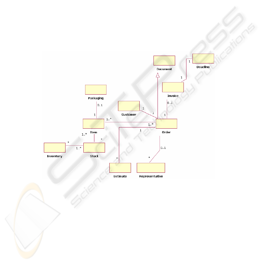
4.1 CIM and PIM Model Elements
In the case of an ERP, the CIM and PIM models are pre-built and represent the enti-
ties of the domain model. In fact, the PIM is not generated from the CIM but it is
tuned according to the target process to implement. The elements of theses models are
business entities represented by the Resource stereotype, which is an extension of the
“Class” metaclass in the UML meta model. According to [6] a resource is an entity
which is either consumed or transformed by a process. Moreover, a Boolean tagged
value is associated to each of these entities to represent the state of the entity: ‘used’
or ‘unused’. Examples of such resources are: item, order, currency, invoice or loan.
Figure 1 shows a subpart of the CIM model built in our prototype system.
Fig. 1. The CIM model.
4.2 PSM Model Elements
The elements of the PSM are specific to each target ERP system. They are imple-
mented as table rows, code units, forms, screens and reports (whose parameters are
usually represented as values in table rows). In our prototype, we targeted Adonix
®
,
one of the leader ERP system in the SMI business segment. Then, the PSM takes the
form of value of rows in the Adonix tables.
80
5 Transforming the CIM to the PIM
On of the key feature of our approach is that the transformation rules from CIM to
PIM and from PIM to PSM are themselves represented as models. In fact, our goal
with this approach was to make it as easy as possible for the ERP customers to use
our tool to configure their system. Then, the CIM to PIM transformation is repre-
sented by the high level model of the generic business process to be implemented in
the ERP. This model is used to propagate tagged values from the CIM to the PIM
depending on the state of each of the business process’ tasks. When an engineer must
configure a transformation, he will simply select the generic process to be imple-
mented from a library, then select the tasks that must be enabled (used) or disabled
(unused) in this process. For example, if a process is disabled, then the linked re-
sources will also be disabled. This will then further propagate to all the processes that
use or manipulate these resources. Next, if a resource represents the output of a dis-
abled process, then it is also disabled and all processes that use this resource as input
will also be disabled. At the end of this propagation step, any OCL constraints that
represent specific limitations, initial values, message or time constraints in the CIM
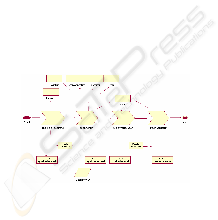
must be copied to the PIM. Figure 2 shows a business process model that represents
the CIM to PIM transformation rule in our prototype system, with its associated re-
sources, people, information and goals.
Fig. 2. Transformation rule: a process model.
The business model that represents the transformation rule from CIM to PIM is built
from the following elements.
81
Business process (stereotype): represents a set of activities to be performed by people.
It may be structured as a hierarchy of sub processes where the lowest level is the
activity. The business process is therefore an extension of the “Activity” metaclass
(fig 3). However, the activities associated to a given process are platform dependent.
Therefore they will be defined when dealing with the PIM to PSM transformation.
When building a process model, the resources must be linked to the business process
which manipulates them.
«MetaClass»
Activity
«Stereotype»
BusinessProcess
+ «TagDefinition» used : Boolean = True
Fig. 3. The Business Process metaclass.
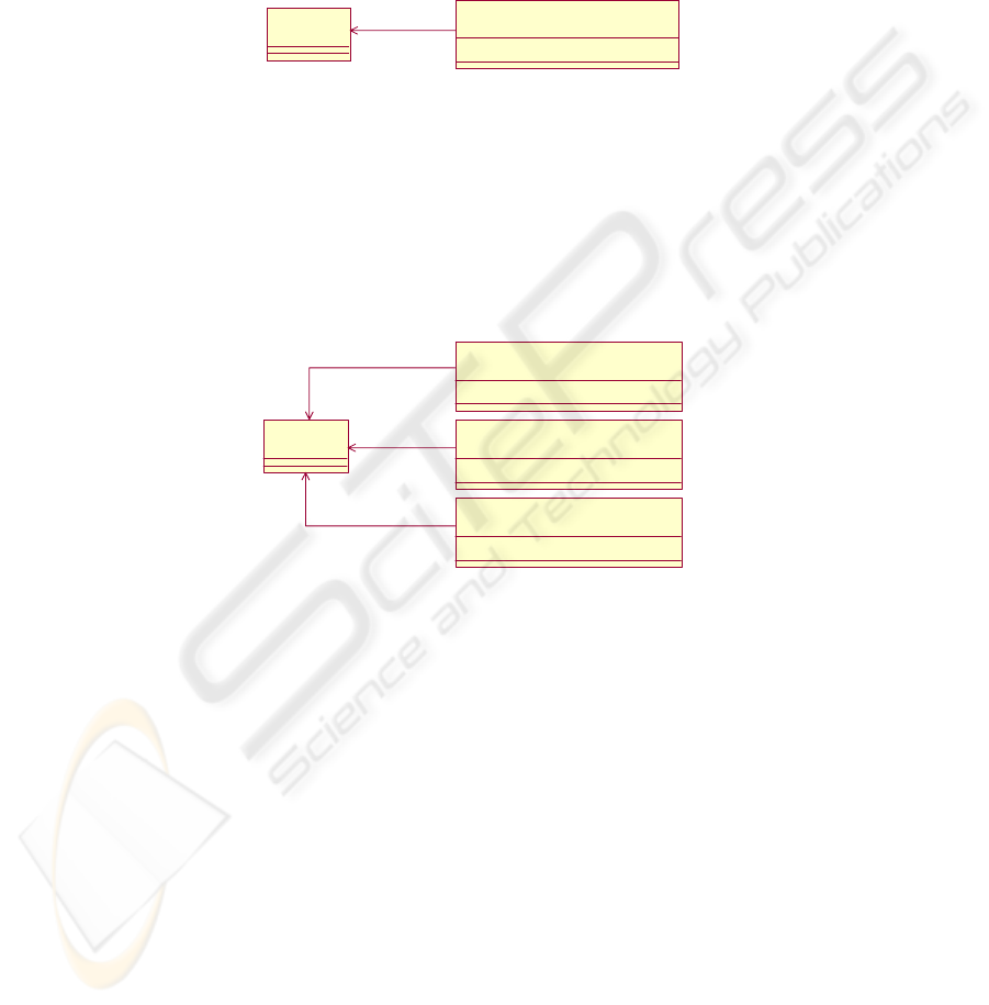
People (stereotype): represents a “human resource” that is associated to a process. It
is an extension of the “Class” metaclass (fig 4). This element is used to define au-
thorizations profiles over the system (access rights to the ERP functions). Goal and
information (stereotypes): represent the business goal of a process and the informa-
tion required to perform a process. These elements must be linked to their business
process. For the moment, these two elements are used for documentation purpose
only. They both are extensions of the “Class” metaclass (fig 4).
«MetaClass»
Class
«Stereotype»
Go a l
+ «TagDefinition» used : Boolean = True
«Stereotype»
People
+ «TagDefinition» used : Boolean = True
«Stereotype»
Inf o r mat ion
+ «TagDefinition» used : Boolean = True
Fig. 4. The metaclasses for resources.
6 Transforming the PIM to the PSM
The PIM to PSM transformation is also represented by a model. In this case it is the
model of the actual implementation, in the target ERP system, of the generic business
process used as the CIM to PIM transformation. This implementation is represented
as a set of Business Activity diagrams, each diagram corresponding to one of the tasks
of the business process. These models are used to configure the PSM model elements
according to the tagged values of the PIM model elements and the status of each of
the activities of the activity diagrams of the tasks. In fact, when an engineer must
configure a PIM to PSM transformation, he will simply select the status of the activi-
ties in the activity diagram that represents the business task to configure. The value of
82
the status of an activity is dependent on the target ERP system. For example, one may
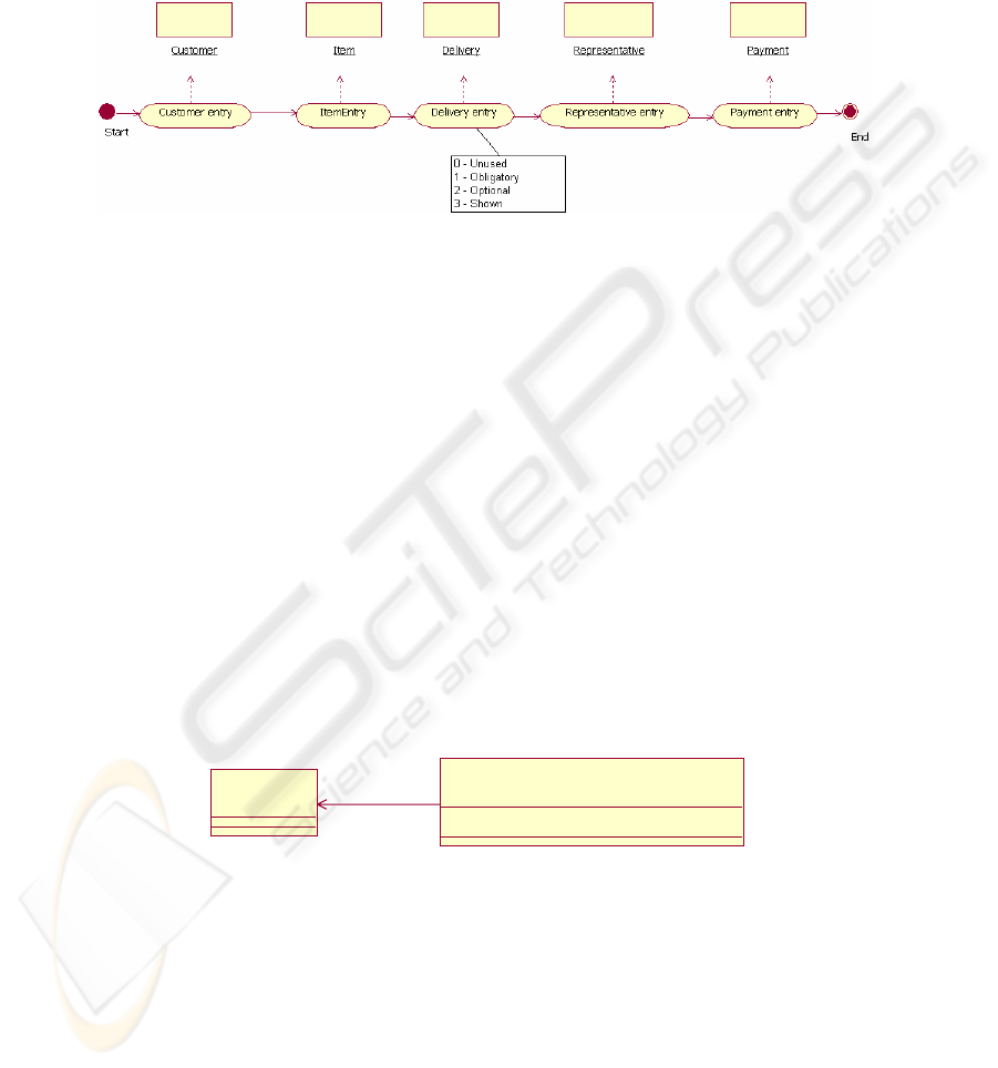
have : unused, optional, obligatory, shown,… In figure 5 we represent a business
activity diagram that shows the entity linked to each of the activities. The figure also
shows a pop up menu that let the configuration engineer choose the status of one of
the activities.
Fig. 5. Business activity diagram for a business process.
The transformation process will propagate the values of the activities’ status to all the
attributes of the linked business entities, unless the latter were already disabled by the
first transformation. For example, if the status of the “Payment entry” activity is set to
“Obligatory” then all the attributes of the linked business entity “Payment” entity will
be set to “mandatory” through the addition of a new property. From the final status of
these entities, the system will generate the parameters for the target platform. Finally
any OCL constraints will be processed to generate the constraint in the appropriate
target format. For example if, as in Adonix, the target of the customization process is
a set of tables, a set of generic SQL scripts will be executed to populate these tables
using a mapping file that holds the mapping from the entities and their attributes to
the tables’ records.
The activity diagram that represents the transformation rule from the PIM to the PSM
is built from the BusinessActivity stereotype which is an extension of the “Activity”
metaclass (fig 6). A business activity may be of type data entry, data validation or
data selection. It is linked to the resources it manipulates. A tagged value “status” is
associated to each business activity to represent the user-selected status of the activ-
ity (see figure 5).
«MetaClass»
Activity
«Stereotype»
Business Activity
+ «TagDefinition» status : String = Optional
Fig. 6. Business Activity metaclass.
The business activity diagram associated to each business task is ERP dependent.
Then, it must be created for each new target ERP platform. Moreover, if the target of
the customization process is a set of tables, one must also create the mapping file
from the business entities to the tables of the target platform. In figure 7, we summa-
rize the steps of the transformation from CIM to PIM to PSM using the technique we
described.
83
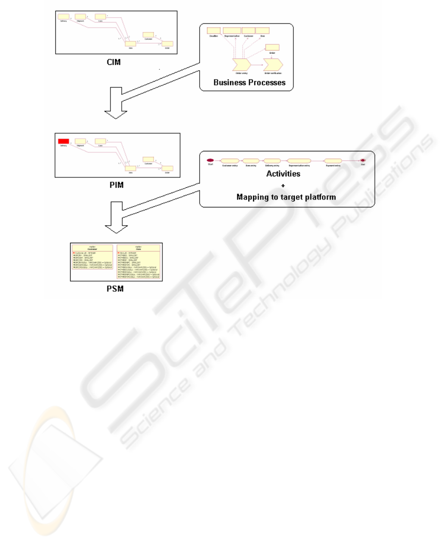
Fig. 7. Summary of the model-based MDA transformations.
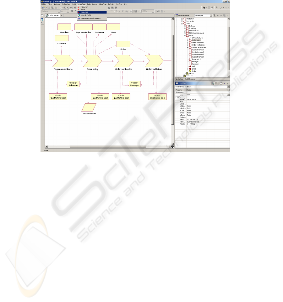
7 Implementation of the Prototype
The prototype of our system has been implemented in the IBM’s XDE environment
augmented with the MDA toolkit (fig 8). Our own extension is built as an eclipse
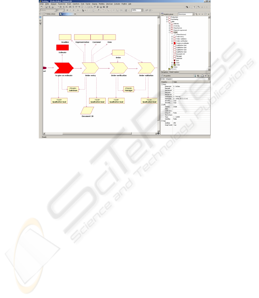
plugin written in Java. When a task of a generic business process is disabled by the
configuration engineer or if an entity gets disabled by status propagation, it is turned
to another color (red) in the diagram. Then it is easy for the configuration engineer to
see the current status of the customization (fig. 9).
8 Conclusion and Future Work
The goal of this project was to validate the applicability of the MDA framework to
the customization of an ERP. The use of an ERP system as the target platform of the
MDA approach brings some unique constraints. First, the final application is not
generated because it already exists. Rather, it must be configured or customized.
84
Second, the process that could be implemented are dependent on what is available on
the target platform. In other words, the spectrum of the possible business process to
implement is limited. Third, although the customization language is specific to each
ERP, the business process to be implemented can be represented by some standard
graphical notation.
Fig. 8. Prototype in the IBM’s XDE environment.
Then we investigated the possibility to use this graphical notation to generate the
customization constraints. This lead us to define the MDA transformations them-
selves as models (business process and business activity diagrams) using a standard
notation (BPML, which has been implemented as a UML Profile). This has the
unique advantage to free the user from knowing the peculiarities of some specific
customization language or system. Using this technique, the customization is self
documenting. The impact of any subsequent change could then be easily analyzed at
a conceptual (business) level. Although our first prototype only covers a small subset
of the business processes of Adonix, we have been able to generate the parameters
down to the Adonix tables successfully, only using our graphical notation. These
parameters triggered the correct behavior on the system. The next step in this research
will be to extend the prototype to the other processes and to further validate the ap-
proach by targeting other ERP platforms (Microsoft’s Navision®). A new topic of
research would be to go the other way around: to generate the high level (business)
view from a given ERP implementation. Although one could already foresee the
many difficulties of this endeavor, the present research has shown some path toward
this goal.
85
Acknowledgement: this work has been supported by the HES-SO 12493 grant (IS-
Net89) from the Swiss Confederation.
Fig. 9. Business process with disabled elements.
References
1. Almeida J.P., Dijkman R., van Sinderen M., Fereira Pires L.:On the Notion of Abstract
Platform in MDA Development. Proc IEEE EDOC (2004)
2. Arinze B. and Anandarajan M.: A Framework for Using OO Mapping Methods to Rapidly
Configure ERP Systems. Communications of the ACM Vol. 46(2) (2003)
3. Baker B.: Business Modelling with UML: The Light at the End of the Tunnel. The Rational
Edge, Rational Software, December (2001)
4. BPMI.org,: Business Process Modeling Notation - Working Draft 1.0 www.bpmi.org.
(2003)
5. Frankel D.S.: Model Driven Architecture. OMG Press. Wiley Publishing, (2003)
6. Eriksson H.-E., Penker M.: Business Modeling with UML. John Wiley & Sons, (2000)
7. Gulla J.A., Brasethvik T.:On the Challenges of Business Modeling In Large Scale Reengi-
neering Projects. 4th International Conference on Requirements Engineering (2000)
8. Harwick T.: Three Half-Truths About Custom Applications, Forrester Inc., November 27
(2002)
9. Heberling M., Maier Ch., Tensi T.: Visual Modeling and Managing the Software Architec-
ture Landscape in a large Enterprise by an Extension of the UML. Second Workshop on
Domain Specific Visual Languages, OOPSLA (2002)
10. Heumann J.: Introduction to Business Modeling Using the Unified Modeling Language.
The Rational Edge, Rational Software, March (2001)
86

11. IDS Sheer : From Process Models to Application, ARIS P2A. White Paper. IDS Sheer AG,
(2003)
12. Jacobson I., Ericsson M., Jacobson A.: The Object Advantage. Business Process Reengi-
neering with Object Technology. Addison-Wesley (1995)
13. Johnston S.: Rational UML Profile for business modeling. IBM Developerworks. www-
128.ibm.com/developerworks/ rational/ library/5167.html (2004)
14. Linvald J., Østerbye K.: UML tailored to an ERP framework. Second Workshop on Do-
main Specific Visual Languages, OOPSLA (2002)
15. Miller J., Mukerji J.: MDA Guide Version 1.0. omg/2003-06-0. OMG, June (2003).
16. Ng P.-W.: Effective Business Modeling with UML: Describing Business Use Cases and
Realizations. The Rational Edge, Rational Software, November (2002)
17. Rolland C., Prakash N.: Matching ERP System Functionality To Customer Requirements.
Proc. Fifth International Symposium on Requirement Engineering, (2001)
18. Scheer A.-W., Habermann F.: Making ERP a Success. Communications of the ACM, Vol
43, N°4 (2000)
19. Thomas J.L.: ERP et progiciels de gestion integrés (ERP and Packaged Business Software).
Dunod, Paris (2002)
20. UML Unified Modeling Language Specification, Version 1.5, OMG, March (2003).
21. van Everdingen Y., van Hillegersberg J., Waarts E.: ERP Adoption by European Midsize
Companies. Communication of the ACM, Vol 43, N°4 (2000)
22. Vogt Ch.: Intractable ERP. A comprehensive Analysis of Failed Enterprise Resource Plan-
ning Projects. ACM SIGSOFT, Software Engineering Notes, 27(2), March (2002)
23. Wegman A., Preiss O.: MDA in Enterprise Architecture? The Living System Theory to the
Rescue. Proc. IEEE EDOC Conference (2003)
87
