
SCALABLE UPDATE PROPAGATION IN PARTIALLY
REPLICATED, DISCONNECTED CLIENT SERVER DATABASES
Liton Chakraborty, Ajit singh, Kshirasagar Naik
Dept. of Electrical and Computer Engineering
University of Waterloo, Ontario, Canada N2L 3G1
Keywords:
Replication, mobile databases, intermittent connectivity.
Abstract:
Modern databases allow mobile clients, that subscribe to replicated data, to process the replica forgoing con-
tinuous connectivity, and to receive the updates while connected to the server. Based on the overlap in client
interest pattern, the server can do update processing for manageable number of data-groups instead of per-
client basis, and hence decouple the update processing cost from the client population. In this paper, we
propose an efficient update propagation method that can be applied to a relational database system irrespective
of its inherent data organization. We present computationally efficient algorithms for group design and main-
tenance based on a heuristic function. We provide experimental results that demonstrate that our approach
achieves a significant increase in overall scalability over the client-centric approach.
1 INTRODUCTION
In Intermittently Connected Database (ICDB) sys-
tems, clients maintain a replica of some subsets of the
global database schema in their local databases to im-
prove performance and availability, and reduce cost.
Updates in the local database are logged and propa-
gated to the server upon resumption of the connection
which is intermittent in nature. The server keeps track
of updates in the primary copy of the global database
and disseminates the updates relevant to the clients
based on the knowledge of their subscriptions. Typ-
ically, the server propagates the updates to clients on
an individual basis: for each client, the server scans
through the whole log of updates and selects updates
relevant to the client. In this way, the server prop-
agates a “client specific” set of updates. This client-
centric approach is simple and straightforward but ex-
pensive in terms of server processing, as the server
load is on the order of the number of clients. So, this
approach limits the scalability of the system.
In (Yee et al., 2001), the authors propose a data-
centric approach that, based on client interests, orga-
nizes updates into limited and controllable number of
groups shared by the clients, and allows the server to
manage update processing, irrespective of the num-
ber of clients, only for those groups. Instead of a cus-
tomized set of updates, each user receives the updates
for the relevant groups. This decoupling of the client
population from server workload in propagating up-
dates leads to better server scalability (Mahajan et al.,
1998) (Yee et al., 2001).
The data-centric approach in (Yee et al., 2001) is
based on a database management system (DBMS) ar-
chitecture, where the database is organized as logi-
cal/physical fragments (Badrinath, 1999). Organiz-
ing a database as logical/physical fragments by parti-
tioning the server data set requires additional features
in traditional DBMS to manipulate and realize frag-
ments. In this approach, clients subscribe to a sub-
set of fragments, and groups are formed according to
the overlap in the client interest pattern. The group-
ing problem, that can be modelled as an NP-complete
mathematical programming problem, is very complex
which makes the heuristic algorithm in (Yee et al.,
2001) computationally inefficient and, hence, time
consuming. And, mapping new client subscriptions
to datagroups, being an NP-complete weighted set
covering problem, is also computationally inefficient.
Hence, activities related to maintaining datagroups—
redesign and datagroup mapping—affect the scalabil-
ity of the system.
Moreover, recognizing or realizing numerous frag-
ments, and specifying interest as a subset of frag-
ments, appear cumbersome. It is convenient to spec-
ify the interest using query in the way similar to spec-
ifying a view. Such a query restricts the data vol-
ume using a few predicates over one or more se-
lected attributes. Also, the previous approach (i.e.,
specifying interest as a subset of fragments) doesn’t
utilize the locality of client data access while form-
ing datagroups: the fragments relevant to a particular
11
Chakraborty L., singh A. and Naik K. (2006).
SCALABLE UPDATE PROPAGATION IN PARTIALLY REPLICATED, DISCONNECTED CLIENT SERVER DATABASES.
In Proceedings of the Eighth International Conference on Enterprise Information Systems - DISI, pages 11-21
DOI: 10.5220/0002490000110021
Copyright
c
SciTePress

client might be contiguous logically (based on some
attributes); hence, they are not always random.
In this paper, we propose an update propagation
method forgoing the assumption about data orga-
nization of the server database. In forming data-
groups, we exploit the locality of client data access.
A client specifies its interest by imposing bound on
the Replica Selection (RS) Attribute(s). We divide the
range of each RS-attribute into equal length consecu-
tive fragments, and associate these fragments with the
nodes of a path graph in order. As the subscription of
a user maps to the consecutive nodes, the problem of
forming groups reduces to the problem of cutting each
path graph (one for each RS-attribute) independently
along few properly selected edges. This splitting of
every path graph creates several connected compo-
nents, that specify the regions of datagroups. This
technique reduces the complexity of forming data-
groups, and maintaining groups with the changes in
ICDB configuration; it eliminates the computational
overhead of mapping new client subscriptions to data-
groups: for fixed number of RS-attributes, this map-
ping can be done in constant time. Also, motivated
by the above example, we allow a portion of client-
centric processing to eliminate redundant updates for
the clients. To eliminate unnecessary updates and
hence to save disk space, we introduce the mechanism
of pruning update logs. All these simplifications en-
hances the scalability of the system.
The rest of the paper is organized as follows: Sec-
tion 2 describes related work in this area. Section 3
outlines the model. Section 4 presents the mechanism
for developing and maintaining datagroups in case of
single attribute replication. Section 5, based on grid
structure, provides a solution for the generalized case.
Section 6 compares our work with intuitive grouping
methods, and demonstrate that our approach provides
significantly greater scalability in client population.
Section 7 provides critical assessment. Finally, sec-
tion 8 concludes the paper and outlines possible future
work.
2 PREVIOUS WORK
Replication in distributed database system is studied
in (Diener et al., 1985) (Demers et al., 1994) (Pacitti
et al., 1999) (Pacitti and Simon, 2000). In the
BAYOU system (Demers et al., 1994), that uses an
epidemic (Demers et al., 1987) approach to main-
tain replica consistency, the whole database is repli-
cated among multiple servers that remain discon-
nected from each other most of the time. Any
read/write operation on the database, by the clients,
is performed on any available server. Using a peer-to-
peer anti-entropy protocol, that allows update propa-
gation among servers that are able to communicate,
the servers propagate updates among copies of the
database (Peterson et al., 1997). Anti-entropy ensures
that in the absence of new updates all the replicas of
the database will converge to identical state provided
the servers don’t remain disconnected forever.
In (Rabinovich et al., 1996), the authors, ad-
dressing the scalability issues in epidemic replicated
databases—to be specific, endeavouring to eliminate
performance degradation due to increase in database
size, propose an epidemic protocol of update propaga-
tion that imposes overhead that is linear in the number
of data items to be copied during update propagation.
Update propagation methods proposed in (Daud-
jee and Salem, 2004; Pacitti and Simon, 2000; Pacitti
et al., 1999) consider the freshness of data, and ensure
the serializable execution of transactions. However,
the techniques assumes persistent connections among
the sites holding the primary and secondary copies of
a database. So, these approaches are not suitable for
and ICDB where the server should store updates and
propagate these updates to the clients upon resump-
tion of the connections.
ICDB is an instance of distributed computing sys-
tem where clients are mobile and commonly suffer
long period of disconnection with the server. Due to
these properties, traditional concurrency control pro-
tocols are not applicable in this system. To help en-
sure the ACID properties of transactions (Bernstein
et al., 1987), traditional distributed database systems
use the two-phase-commit protocol which is commu-
nication intensive and requires all participants to be
simultaneously connected; therefore this protocol is
impractical in a disconnected environment. To ame-
liorate this problem, researchers have proposed repli-
cating data among the clients and allowing indepen-
dent operation on the replicas (Breitbart and Korth,
1997). Two-tier replication model, proposed in (Gray
et al., 1996), though relaxes the ACID properties,
provides high availability, reduces the possibility of
deadlock, reduces the need for continuous communi-
cation with the server, and allows mobility resistant
to network outage. In (Yee et al., 2001), the authors
propose an update propagation algorithm to make the
server workload in update propagation independent of
client population.
The architecture and goal of CODA file sys-
tem (Satyanarayanan et al., 1993) is similar to those of
ICDB: it allows clients to form replicas while discon-
nected, and re-integrate the updates while connected
to the server. However, contrary to ICDB systems,
latency in this re-integration is not observed to be a
limiting factor in CODA.
Update propagation in ICDB systems bears sim-
ilarity with view maintenance (Gupta and Mumick,
1995). The difference is that in view maintenance
the resultant view should match the expected query as
ICEIS 2006 - DATABASES AND INFORMATION SYSTEMS INTEGRATION
12
Mobile
node
Mobile
node
Mobile
node
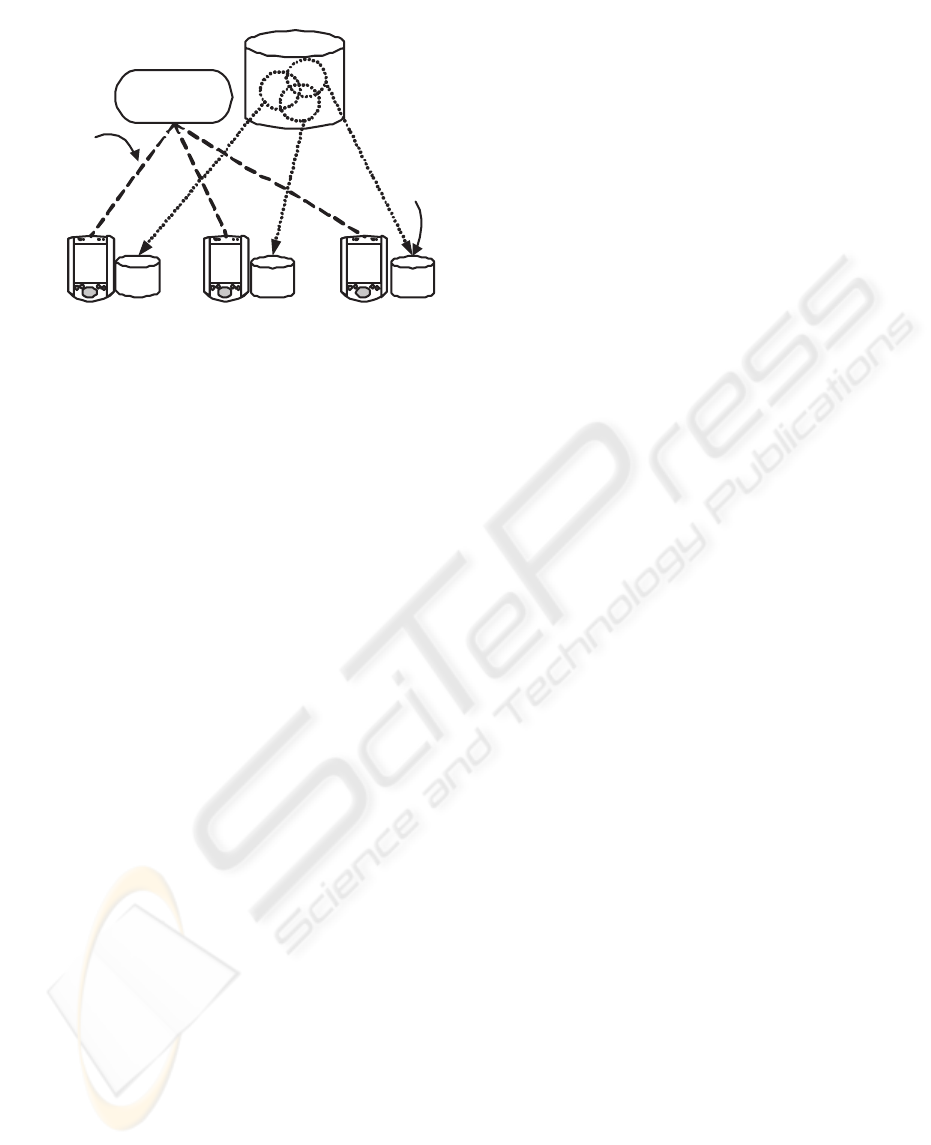
Periodic
connectivity
Global db
Local
db
Update
Manager
Figure 1: The Update Manager maintains the update log and
distributes updates to the intermittently connected clients
that maintain a replica of the global database.
closely as possible with disk space consumption being
the cost factor, whereas in group design, the updates
for each client should be generated as quickly as pos-
sible (Yee et al., 2001). Moreover, modification of a
view by using only view is not always possible.
3 SYSTEM MODEL
The ICDB architecture consists of a database server,
a network and several clients. The global database is
stored in the database server. Closely tied with the
DBMS is the update manager which can either be a
module in a server incorporated with the DBMS, or
be a process running in a stand-alone update server.
This Update Manager stores updates in the database,
keeps track of the client subscriptions, and propagates
updates to the clients when they are connected to the
server via a network (Figure 1). The client is com-
posed of a client update agent, and a local DBMS.
The update agent receives updates from the server and
applies these updates to the replica stored in the local
DBMS.
The update manager stores updates separately for
all datagroups. Updates in a group are removed as
soon as all the clients subscribing to that group con-
nect to the server and, therefore receive the updates.
The time elapsed between successive update removal
of a group is denoted as pruning interval (T ). This
pruning interval of a group is dependent on the fre-
quency of connection resumption by the clients rele-
vant to that group. For the sake of simplicity of our
analysis, we assume that this interval is fixed, and
same for all groups. Designing datagroups without
this assumption is straightforward, but complicates
the cost equations.
We don’t make any assumption about the transac-
tion processing protocol that maintains replica con-
sistency. To maintain replica consistency trans-
action processing protocols based on precedence
graph (Davidson, 1984) can be applied in this envi-
ronment.
In our model, the representation of datagroup, and
fragment (in single attribute replication) or grid-block
(in multi attribute replication) is simple; hence, this
information can be stored in main memory. So, as
new updates arrive in the database, these updates can
be mapped to the datagroup, using the information
stored in memory. This eliminates the need for a tem-
porary log file to store the updates, and map these
updates to datagroup intermittently during an update
session (Yee et al., 2001).
To synchronize a client, while connected to the sys-
tem, the update manager retrieves, and then merges,
updates from relevant datagroups. These merged up-
dates are then scanned to remove redundant updates.
As no redundant update is sent to the client via wire-
less link, the update transmission time play no role in
the datagroup formation. This implies, we don’t make
any traded between server side delay (i.e., disk I/O)
and transmission delay. However, this “scanning” de-
mands CPU time. But, as the scan time is quite in-
significant compared to disk I/O time, we eliminate
this scan time from our cost model.
Each client specifies its desired data, and hence cre-
ate replica, using attribute(s) of a relation. We iden-
tify such attribute as Replica Selection (RS)-attribute
of the relation. For example, consider schema (Badri-
nath, 1999):
SUPPLY(SNUM, PNUM, DEPTNUM, QUAN)
The domain of DEPTNUM is [1...30] and that of
PNUM is [1... 400]. Now, a client can create a replica
of this relation using the following expression:
11 ≤ PNUM ∧ PNUM ≤ 20
Here, PNUM is the RS-attribute of the relation. As
can be observed, if there is only one RS-attribute
of a relation then datagroups can be managed effi-
ciently. But, if there are multiple RS-attributes then
the process of managing datagroups becomes com-
plex. We consider these two scenarios in the subse-
quent part of this paper. A In section 4, we consider
replication with single RS-attribute, that is linearly or-
dered; in section 5, we consider multiple RS-attribute
replication, where RS-attributes are not necessarily
linearly ordered.
4 SINGLE RS-ATTRIBUTE
REPLICATION
In this section, we consider replication with single
RS-attribute; we denote the RS-attribute common
SCALABLE UPDATE PROPAGATION IN PARTIALLY REPLICATED, DISCONNECTED CLIENT SERVER
DATABASES
13

avg
R
Replication Interval
F
r
r
l
r
i+3
F
i+2
F
i+1
F
i
Figure 2: Mapping a replication interval R
avg
to fragments
where r
l
and r
r
are the redundant intervals. The range of
CRS-attribute is represented as the straight line.
to all clients as i common replica selection (CRS)-
attribute. We assume that clients form a replica by
specifying a bound on a particular CRS-attribute, that
spans an interval in the range of this attribute. We call
this interval a replication interval of that attribute.
The range R =[crs
min
,crs
max
] of a CRS-
attribute is divided into a set of non-overlapping in-
tervals or fragments F =(F
1
,F
2
,...,F
n
) where,
n =
crs
max
−crs
min
+1
l
F
i
=
[crs
min
+(i − 1)l, crs
min
+ il] , 1 ≤ i<n
[crs
min
+(i − 1)l, crs
max
] ,i= n
Here, l denotes the length of fragment other than the
last one. We present a method of estimating a suitable
value of l based on limiting the percentage of redun-
dancy (r) while mapping a replication interval to a
number of consecutive fragments.
Let R
av g
be the average replication interval. As
shown in Figure 2, while mapping the replication in-
terval R
av g
to fragments F
i
, F
i+1
, F
i+2
and F
i+3
,
the redundant intervals on the left and the right end
are r
l
and r
r
respectively. These redundant intervals
arise, as a replication interval is mapped to an integral
number of consecutive fragments. Here, as a replica-
tion interval starts and ends at random location within
a fragment, the expected value of both r
l
and r
r
is
l/2. (Although the length of the last (nth) fragment
is different from the rest, for the simplicity of the cal-
culation we consider all fragments to be of length l.)
So, the total expected redundant interval is l or one
fragment length. So,
The percentage of redundancy, r =
l
R
avg
+ l
× 100 %
Given the value of r, l can be calculated from the
above equation. Having the value of R
av g
fixed,
lower r-value results in lower l-value and therefore
larger number of fragments. The value of r (0 <r<
100) is set to a particular value (say, 10%) by the sys-
tem administrator.
The portion of updates applied to a fragment F
i
during a pruning interval is estimated by its weight
W
i
. This weight can be determined as a function of
fragment size and the number clients (n
i
) subscrib-
ing to it. Here, the number of clients subscribing to
a fragment is regarded as the subscription level of the
fragment. The size of fragment F
i
refers to the num-
ber of tuples in the database spanned by the fragment.
W
i
=
size(F
i
) × n
i
i|F
i
∈F
size(F
i
) × n
i
The server forms a set of datagroups G =
{G
1
,G
2
,...,G
M
} where each datagroup consists of
a set of consecutive fragments. Updates to the frag-
ments of each datagroup are stored in a separate up-
date log file.
Having described the details of the system, our goal
is to cluster the set of fragments into a set of data-
groups G that minimizes the total cost function as de-
scribed in the following subsection.
4.1 Cost Model
Though our model assumes a portion of client-centric
processing to remove redundant updates, our cost
model estimates only the disk I/O time, as CPU time
is negligible compared to the disk I/O time. In our
approach, fragment definition is simple and update to
fragment mapping is also a simple operation. More-
over, each group can be defined simply as a list of
consecutive fragments. Hence, we can store the group
definition table in the main memory because of its in-
significant space requirement.
Updates of each datagroup are stored in sepa-
rate update log file. As the size of the update log
file increases, additional disk space is assigned to
it in chunks of sectors called allocation units or
blocks (Ng, 1998). In this scenario, it is highly im-
probable that the allocation units of a log file be con-
tiguous (Tanenbaum, 1996). So, total seek time and
rotational latency, experienced in retrieving a log file,
increases linearly with the number of allocation units
spanned by it. We take this into consideration while
developing the cost function in the subsequent part of
this subsection. We assume that each block except
the first one in a log file imparts delay equivalent to
the disk latency.
The total cost, that represents server processing
within a pruning interval (T ), consists of the four
server activities: update mapping (mapping of up-
dates to the corresponding datagroups), update stor-
age (storage of all updates onto disk), update propa-
gation (retrieval and transmission of update logs), and
update pruning (elimination of unnecessary updates
from the disk). Here, the cost of each activity is mea-
sured by time delay experienced in it. The total cost
is therefore:
Total Cost = Update Mapping Cost + Storage Cost
+ Propagation Cost + Pruning Cost
The variables used in the cost function and in the
subsequent analysis are given below:
ICEIS 2006 - DATABASES AND INFORMATION SYSTEMS INTEGRATION
14

Variables Description (unit, if applicable)
C
S
server disk seek time(sec)
C
L
server disk rotational latency(sec)
C
D
C
S
+ C
L
, disk access time (sec)
C
R
server disk transfer rate(sec/byte)
S
C
allocation unit or block size of
inherent file system(bytes)
S
U
size of each update log (bytes)
λ total update arrival rate of the
replicated fragments (updates/sec)
B datagroup buffer size (bytes)
S
k
set of datagroup relevant to client k
N number of clients
T pruning interval (sec)
M number of datagroups
Update mapping cost is the time required to map
the updates to the datagroups. While an update ar-
rives, it can be mapped to the relevant update without
any disk access. So, For each update,
Update Mapping Cost =0
Update storage cost indicates the time needed to
store all the update logs onto disk at the server. We
assume that a main memory buffer is maintained for
each datagroup, and whenever a buffer is filled, its
content is written to disk.
Update Storage Cost
=
M
j=1
C
D
λT S
U
B
i|F
i
∈G
j
W
i
+ C
R
λT S
U
i|F
i
∈G
j
W
i
The left term indicates the disk access time while
dumping the content of datagroup buffer to the disk,
and the right term indicates the actual transfer time.
Update propagation cost measures the time re-
quired to load the updates into main memory, scan
the updates and transfer the appropriate update logs
to the client. As stated earlier, we include only the
retrieval cost of the updates.
Update Propagation Cost
=
N
k=1
C
D
|S
k
| +
G
i
∈S
k
λT S
U
S
C
j|F
j
∈G
i
W
j
− 1 C
L
+ C
R
λT S
U
G
i
∈S
k
j|F
j
∈G
i
W
j
Here, the first term in the parentheses stands for the
disk access time, the second term for the latency, and
the last one for transfer time, while retrieving log files
of the datagroups relevant to client k.
Pruning cost includes the time necessary to scan
the log files to eliminate the unnecessary updates. As
this activity is performed at the end of each pruning
interval (T ), each log file contains the updates stored
in time period 2T . So,
Pruning Cost
= MC
D
+
M
k=1
⎛
⎝
⎡
⎢
⎢
⎢
λT S
U
S
C
i|F
i
∈G
k
W
i
⎤
⎥
⎥
⎥
− 1
⎞
⎠
C
L
+ C
R
λT S
U
i|F
i
∈G
k
W
i
Here, the first term stands for the total access time for
all datagroups. Within the summation, the first term
indicates the latency for a datagroup, and the second
term indicates the transfer time.
4.2 Datagroup Design and
Maintenance
4.2.1 Preliminaries
A path graph P is a simple connected graph with
|V
P
| = |E
P
| +1that can be drawn so that all of
its vertices lie on a single straight line (Gross and
Yellen, 1999). An n-vertex path graph is denoted as
P
n
. While deleting a node v
i
from P
n
we add an
edge (v
i−1
,v
i+1
) if i =1and i = n. Similarly while
deleting a set of connected nodes {v
i
,...v
j
}, i<j,
we add an edge (v
i−1
,v
j+1
) if i =1and j = n.To
insert a node v
in P
n
at position i, 1 ≤ i ≤ n +1we
• add edge (v
i−1
,v
),ifi>1,
• add edge (v
,v
i
),ifi = n +1and
• remove (v
i−1
,v
i
),if1 <i≤ n.
We map the set of fragments F =(F
1
,...,F
n
) to
the set of nodes V =(v
1
,...,v
n
) of path graph P
n
in order so that F
1
maps to v
1
, F
2
to v
2
and so on.
All the nodes in P
n
with zero subscription level are
deleted resulting in a path graph P
m
(m ≤ n).We
call this resulting path graph P
m
as truncated path
graph. Associated with each node v
i
of this truncated
path graph P
m
is the following information:
1. f (v
i
) fragment which v
i
corresponds to,
2. f
i
number of clients subscribing to node v
i
, and
3. f
i,i+1
number of clients accessing v
i
and v
i+1
(1 ≤
i<m) simultaneously.
To split the path graph along edges, we calculate
the redundancy factor RF
i,i+1
associated with each
of the edges (v
i
,v
i+1
), (1 ≤ i<m). This redun-
dancy factor indicates the ratio of cumulative redun-
dant updates to cumulative update volume — both of
the two terms consider the updates from fragments
corresponding to v
i
and v
i+1
only — accessed by
clients subscribing to fragments corresponding to v
i
and/or v
i+1
. This parameter can be calculated as fol-
lows.
SCALABLE UPDATE PROPAGATION IN PARTIALLY REPLICATED, DISCONNECTED CLIENT SERVER
DATABASES
15
Let, f
i,i+1
denote the total number of clients sub-
scribing to v
i
, but not to v
i+1
; and f
i,i+1
the number
of clients subscribing to v
i+1
, but not to v
i
.Now,
f
i,i+1
= f
i
− f
i,i+1
f
i,i+1
= f
i+1
− f
i,i+1
Average number of updates accessed by a client from
the fragment f (v
i
) associated with v
i
can be given
as λT W
f(v
i
)
. When nodes v
i
and v
i+1
belong to the
same datagroup, total volume of redundant updates
(R
i,i+1
) accessed by all clients from the fragments
corresponding to these nodes can be written as fol-
lows:
R
i,i+1
= f
i,i+1
λT W
f(v
i
)
+ f
i,i+1
λT W
f(v
i+1
)
Now, total update volume (C
i,i+1
) accessed by all
clients from the fragments corresponding to nodes v
i
and v
i+1
can be derived as:
C
i,i+1
= λT (f
i
+f
i+1
−f
i,i+1
)
W
f(v
i
)
+ W
f(v
i+1
)
So, Redundancy factor, RF
i,i+1
=
R
i,i+1
C
i,i+1
(1)
4.2.2 Datagroup Design
We design the datagroup by splitting the truncated
path graph P
m
(V,E) along edges (termed as split
edge) selected in the decreasing order of their values
(i.e., redundancy factor). We carry on the splitting un-
til no cost-effective split operation is possible.
Algorithm Datagroup-Design
begin
While TRUE do
select an edge e ∈ E with maximum value
if split along e is not cost-reducing, then quit.
delete e from E.
end
end
4.2.3 Operators for Redesigning Datagroups
Merge operation involves replacing two datagroups
by their union. While merged, clients subscribing to
both the datagroups have to access one datagroup in-
stead of two, reducing the delay due to disk latency.
But, redundant updates for the clients subscribing to
only one of the datagroups increase. We try to ap-
ply merge operation when redundancy factor of a split
edge connecting two datagroups becomes less than
that of an edge within one of these groups.
Split operation involves dividing a datagroup,
along the split edge, into two datagroups. We apply
split operation after merging two or more datagroups.
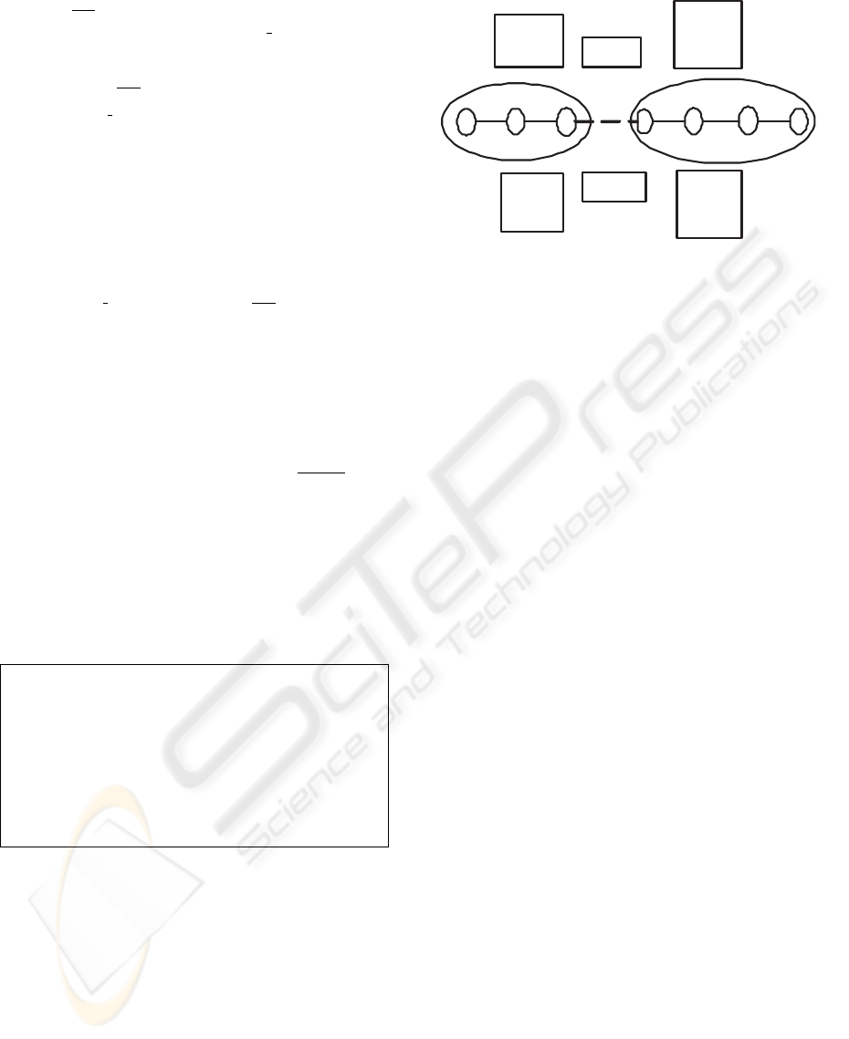
G
i+1
G
i
At t
1
:
a
b
s
c d e
c: 0.25
d: 0.27
e: 0.20
s: 0.4
c: 0.30
d: 0.40
e: 0.25
s: 0.35
At t
0
:
a: 0.1
b: 0.2
a: 0.20
b: 0.25
Figure 3: Weights of the edges at t
0
and t
1
are shown above
and below respectively. The split edge (s) of groups G
i
and
G
i+1
is shown as broken line.
4.2.4 Redesign
As time passes, the configuration of the ICDB
changes. New clients may be added periodically.
Moreover, existing clients may change their subscrip-
tions. Hence, the number of nodes and value of the
edges change in the truncated path graph.
In our approach, the redesign of the groups, that is
performed periodically after a time interval, is sim-
ple. For this purpose we merge two groups pairwise
if the precondition of merge holds, and in the merged
groups we apply split operations. Edges in the merged
group are considered in the decreasing order of the
weight until no cost benefit splitting is possible. So,
redesign is performed locally keeping the remaining
groups un-affected.
Example: In Figure 3, two datagroups G
i
and G
i+1
with three and four fragments respectively are shown.
Weights of the edges at time t
0
are shown above in the
figure. After certain interval (at time t
1
) the weights
are as shown below in the figure. At time t
1
, d ex-
ceeds s ( the split edge). So, these two groups are
merged, and the merged group is splitted, if feasible,
along edges d, s, c, b, e, a in that order.
5 MULTI-ATTRIBUTE
REPLICATION
The datagroup design described in the previous sec-
tion is based on a single linearly ordered RS-attribute:
all the clients must form their replicas using that at-
tribute. In this section, we consider the design and
maintenance of datagroups in an ICDB environment
where replicas can be specified using multiple RS-
attributes; and all of these RS-attributes may not nec-
essarily be linearly ordered. In forming replicas,
clients, instead of specifying bounds, may specify dis-
crete values for some RS-attributes, which we call
ICEIS 2006 - DATABASES AND INFORMATION SYSTEMS INTEGRATION
16
discrete RS-attributes. Here it should be noted that
the RS-attributes are generally identified as discrete
based on the application semantics: for example, it
is desirable for the clients to specify the department
(using RS-attribute DEPT-NAME) as discrete point
in the domain of DEPT-NAME rather than as bounds
on that RS-attribute.
To design and maintain datagroups with multi-
ple RS-attributes, we use the notion of grid parti-
tion of tuple space and of grid directory, which are
keys to a dynamic multi-key file structure called the
grid file (Nievergelt and Hinterberger, 1984). While
the notions are used in (Nievergelt and Hinterberger,
1984) to provide both efficient processing of range
queries and fast access to individual records, we ap-
ply the notions to increase the performance of ICDB
system in storing and retrieving updates for a group
of clients. The design of datagroup requires us to di-
vide the range of RS-attributes into fragments, and
thus obtain the grid partition; form path graph cor-
responding to RS-attribute on each axis; divide the
grid partition into k-dimensional rectangles by greed-
ily splitting along the axes: each of the rectangles cor-
responds to a datagroup. Thus we divide the tuple
space into grid blocks.
The attribute fragments can be constructed in two
ways depending on the type of the attribute (i.e., lin-
early ordered or discrete). For a linearly ordered RS-
attribute, the range of the attribute can be fragmented
using the technique described in section 4. For a dis-
crete RS-attribute, we use the vertical partitioning al-
gorithm (Chakraborty et al., 2002) to cluster the at-
tribute values. The attribute values are clustered based
on the affinity between attribute values (we measure
the affinity between two values by the number of
clients, that explicitly specify both of these two val-
ues using the corresponding RS-attribute). Upon par-
titioning the range of the RS-attribute, each cluster of
the attribute values corresponds to a fragment of the
corresponding attribute.
The information about the grid partition is main-
tained using a data structure called grid directory. A
grid directory consists of two parts: a k-dimensional
array called grid array, and index information associ-
ated with each dimension of the grid array. Elements
in grid array are in one-to-one correspondence with
the grid blocks of the partition. Each of these el-
ements is either a structure or pointer to a structure
that contains the following information about the cor-
responding grid block:
1. size of the grid block (in number of tuples)
2. number of clients subscribing to the grid block
3. weight of the grid block
The index information associated with each axis
of grid array provides the representation of attribute
fragment corresponding to each possible index value
y
1
1
x
2
x
7564
32
5
Y
89
1
X
XX
XX
X
X
X
X
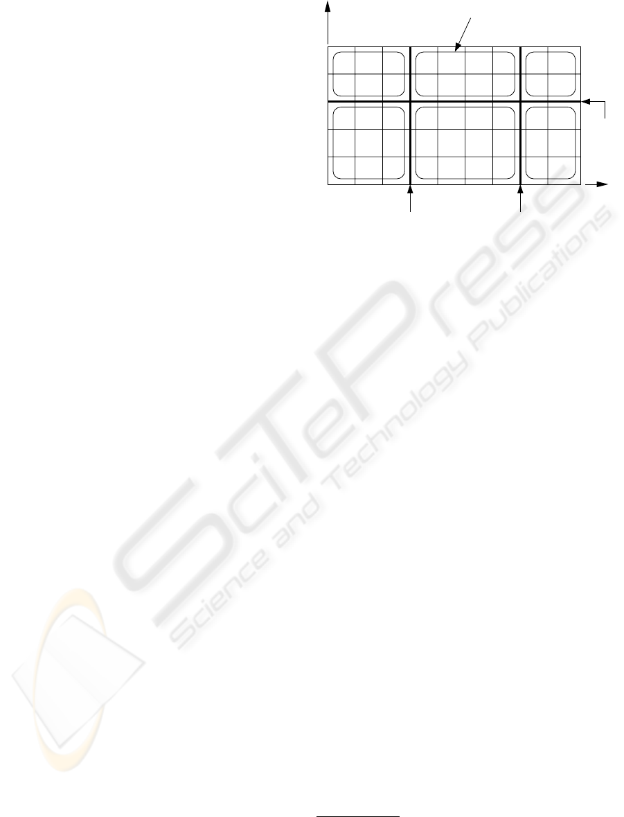
Datagroup
1
2
3
4
Figure 4: Datagroup formation in a two dimensional grid
array. The split locations on x-axis are x
1
and x
2
, and that
on y-axis is y
1
. The splitting lines are indicated by dark
lines. Redundant blocks within a datagroup are indicated
by “X” symbol.
along that axis—the relevant attribute being obvious
from the axis. As noted earlier, this index information
for a linearly ordered attribute can be represented by
the range and the fragment length (l) of the attribute.
Using this information the fragment corresponding to
an index value can be derived, and, on the other hand,
for an attribute value the corresponding fragment or
index can also be calculated. However, the index in-
formation is no longer simple for discrete attributes,
as each fragment of these attributes should have ex-
plicit representation. In this case, we use an one di-
mensional array, where each location points to the
corresponding fragment definition structure. We as-
sume that the number of distinct values of a discrete
RS-attribute is not prohibitively high; so that the in-
dex information consumes insignificant memory, and
partitioning attribute values remains simple.
The index information of an axis should store the
list of redundant index locations along the axis; mark-
ing an index location of an axis redundant we virtu-
ally eliminate a (k − 1)-dimensional subsection of
the grid array. We call an index location redundant
if the subscription level of the fragment correspond-
ing to the index value is zero and, while forming
replica, the corresponding attribute is explicitly spec-
ified by all clients (we don’t consider PNUM=“*” an
explicit specification of PNUM). However, elimina-
tion of these redundant index locations doesn’t re-
move all the redundant blocks
1
in the grid array.
There may remain some redundant blocks or holes
(Figure 4) that should be identified, and be excluded
1
A grid block that is not replicated by any client is re-
ferred to as redundant block; otherwise a grid block is called
replicated block
SCALABLE UPDATE PROPAGATION IN PARTIALLY REPLICATED, DISCONNECTED CLIENT SERVER
DATABASES
17
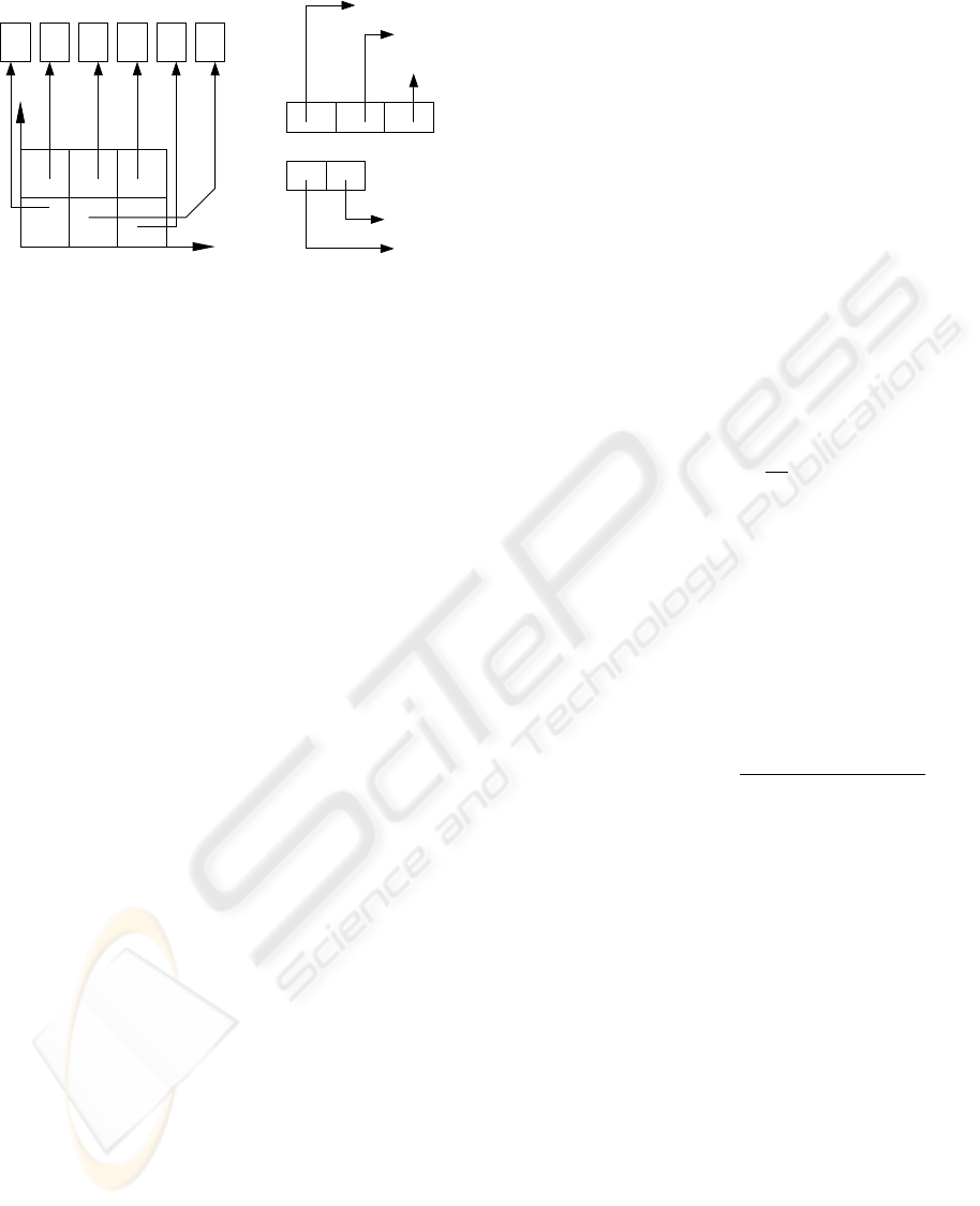
(b)
(a)
(1 −
3)
(4 −5
)
(4 −
7)
(8−9)
X:
(1−3)
Y
DataGroup Record
Y:
X
Figure 5: Datagroup array represents the datagroup formed
by partitioning the grid array (Figure 4). The index informa-
tion stores the locations of grid array corresponding to each
index value of the respective axis (of datagroup array). A
datagroup record stores the list of redundant blocks within
each datagroup.
from the datagroups.
Datagroups are formed by partitioning the grid ar-
ray into non-overlapping k-dimensional rectangular
regions. This partitioning involves choosing few suit-
able locations on each axis, and cutting the grid ar-
ray with hyperplanes orthogonal to the axis on the se-
lected locations. The boundaries of these planes de-
fine the datagroups. Figure 4 shows datagroup forma-
tion for the case k =2, from which the general case
k>2 can easily be inferred. Here, datagroups are
formed by splitting the grid array by lines perpendic-
ular to x-axis on x
1
and x
2
, and by that perpendicular
to y-axis on y
1
. Three of the six datagroups formed
contain redundant blocks, that don’t fall within any
redundant index of any of the axes.
To represent the datagroups we use an array, that
we call datagroup array (D), and the associated in-
dex information. Size and shape of this datagroup ar-
ray depends of the number of splits across each of the
axes. As shown in Figure 5, the shape of the data-
group array derived from the grid array of Figure 4 is
(2 × 3). Each element in the datagroup array corre-
sponds to a datagroup, and it points to a record that
stores the list of redundant blocks within that data-
group. The index information associated with the
datagroup array is maintained the same way as with
the grid array: a one dimensional array is maintained
for each axis; and this array stores the range of in-
dex locations of the grid array spanned by each index
value of the corresponding axis of the datagroup ar-
ray.
In reality, there will be only few datagroups; so the
datagroup array and its associated index information
are stored in main memory, but the records pointed to
reside in the disk.
5.1 Cost Model
The cost function for replication with multiple at-
tributes is similar to that developed in section 4. How-
ever, we introduce here minor changes in parameters,
and in update storage cost. In this case, F
i
should
represent grid blocks instead of fragments.
As outlined earlier, the index information (associ-
ated with grid array), the datagroup array and its index
information are stored in main memory. But, data-
group records associated with each datagroup reside
in disk. In this respect, updates from the redundant
blocks within a datagroup can’t be filtered out without
these datagroup records. So, some redundant updates
should be stored in the datagroup buffers. Hence, the
update arrival rate (from the point of view of data-
group buffers) is no longer λ. We denote this update
arrival rate of blocks within datagroups (redundant or
replicated) as λ
d
, and estimate it as follows:
λ
d
= λ ×
S
d
S
r
(2)
Here, S
d
is the size of all the grid blocks (replicated
or redundant) within a datagroup, and S
r
is the size of
all the replicated grid blocks.
While storing updates, as a datagroup buffer be-
comes filled, the corresponding datagroup records are
retrieved from the disk; redundant updates are then
removed, and relevant updates are stored in the disk.
So, updates arrive on disk side at the rate of λ.Now,
Update Storage Cost
=
M
j=1
(2C
D
+ C
R
S
D
)
λ
d
TS
U
i|F
i
∈G
j
W
i
B
+ C
R
λT S
U
i|F
i
∈G
j
W
i
Here, S
D
= average datagroup record size
5.2 Datagroup Design
While forming datagroups, the axes corresponding to
different types of attributes are treated differently. For
linearly ordered RS-attributes, the corresponding axes
of the grid array are splitted at various suitable lo-
cations. To determine these locations we maintain a
path graph for each of such attributes or axes. On the
other hand, for discrete RS-attributes, the index val-
ues of the corresponding axis are clustered together.
To cluster these index values, for such attributes, we
maintain a minimum spanning tree.
For each linearly ordered RS-attribute, we main-
tain a path graph the same way as described in sec-
tion 4. In case of discrete RS-attribute i, each in-
dex location (k) of the corresponding axis in grid
ICEIS 2006 - DATABASES AND INFORMATION SYSTEMS INTEGRATION
18

array corresponds to a cluster of values of that at-
tribute (i.e., attribute fragment (p
i
k
) ). In this cluster-
ing operation the cost factor is not considered. So,
further grouping of these clusters is attempted tak-
ing the cost factor into consideration. For such an
attribute i, we form a redundancy graph (G
i
) with
vertex set V
i
=
v
i
1
,v
i
2
,...,v
i
n
i
, where each vertex
corresponds to a fragment of attribute i. Each node
v
i
k
of this graph stores f
i
k
, which is the number of
clients subscribing to corresponding fragment (p
i
k
).
Initially, the value of each edge (v
i
j
,v
i
k
) is the number
of clients (f
i
j,k
) subscribing to both of the fragments
corresponding to v
i
j
and v
i
k
(i.e., p
i
j
and p
i
k
respec-
tively). We calculate the redundancy factor RF
j,k
for
each edge (v
i
j
,v
i
k
) and associate this with the respec-
tive edge.
RF
i
j,k
=
f
i
j
− f
i
j,k
W
i
k
+
f
i
k
− f
i
j,k
W
i
l
f
i
j
+ f
i
k
− f
i
j,k
W
i
j
+ W
i
k
Here, W
i
j
and W
i
k
are the sum of the weight of all
replicated grid block whose ith index value is j and k
respectively.
Having derived this redundancy graph G
i
,we
obtain the minimum spanning tree of this graph
MST(G
i
). While forming datagroups, we use this
graph to cluster the indices of axis i of the grid array.
This clustering is done by splitting MST(G
i
) along
suitable edges, and hence forming the groups of index
values.
5.3 Splitting Policy and Redesign
Several splitting policies are possible, while forming
datagroups. The simplest one is to choose the di-
mension or axis according to a fixed schedule, per-
haps cyclically. The corresponding axis is splitted
by selecting the edge with maximum value from the
path graph (in case of linearly order RS-attribute), or
from minimum spanning tree (in case of discrete RS-
attribute), of the corresponding axis. We carry on the
splitting until no cost-effective split operation is pos-
sible.
Having finished the splitting, the datagroup array is
built, where index information associated with each
axis reflects the splitting done along that axis, and
the datagroup records store the list of redundant grid-
blocks within each datagroup.
As the configuration of the ICDB changes, data-
groups can be redesigned using the method described
in section 4. The merge and split operation can be
applied along different axes independently. Thus, in
case of multiple attribute replication, it is possible
to redesign datagroups without beginning from the
scratch.
6 SIMULATION EXPERIMENTS
This section describes our methodology for evalu-
ating the update propagation scheme, and presents
an experiment demonstrating the effectiveness of the
proposed update propagation scheme. We begin with
an overview or the experimental design of the simu-
lator and description of the ICDB environment. We
then show that data-centric grouping (dc) of updates
using our proposed algorithm results in faster per-
client refresh times than other more intuitive methods.
Refresh time includes the time required for the server
to store the updates in the log files, retrieve the rele-
vant updates to propagate to the clients, and prune the
update log files after each pruning interval.
6.1 Simulation Model
In our simulation, we assume that all clients connect
to the server within each pruning interval (T ); how-
ever, the connection time of a client is uniformly dis-
tributed over that interval. The update logs are pruned
at the end of each pruning interval
2
. Each client sub-
scribes to the a certain portion of the database, which
we call the percent of replication (p%). From this
percent of replication we derive the replication inter-
val (R
av g
) of the clients along each RS-attribute, and
this replication interval is randomly chosen from the
range of each RS-attribute. We consider the update
arrival rate proportional to the number of clients. The
updates are distributed to the grid blocks according to
their weights. In this simulation, we consider replica-
tion of a database relation schema with two linearly
ordered RS-attributes.
To compare with our scheme we consider two up-
date propagation schemes: clients centric scheme (cc)
and the scheme with one giant group (gg), that are de-
scribed in Table 1. We show that as the client popula-
tion and the per-client update arrival rate increase, the
advantage of dc increases over other techniques: per-
formance gains generally come from avoiding redun-
dant update storage and retrieval by identifying the
overlapping subscriptions.
6.2 Experiments and Results
To measure the effectiveness of our data-centric
scheme (dc) we measure the per-client refresh time
for varying client population and per-client update ar-
rival rate (u
rate
). The experimental parameters are
given in Table 2. For each setting of experimental
parameters we run the simulation for 10 simulation
hours.
2
Maintaining the update logs with widely varying con-
nection intervalsof the clients is a separate issue that is stud-
ied in (Chakraborty et al., 2004)
SCALABLE UPDATE PROPAGATION IN PARTIALLY REPLICATED, DISCONNECTED CLIENT SERVER
DATABASES
19
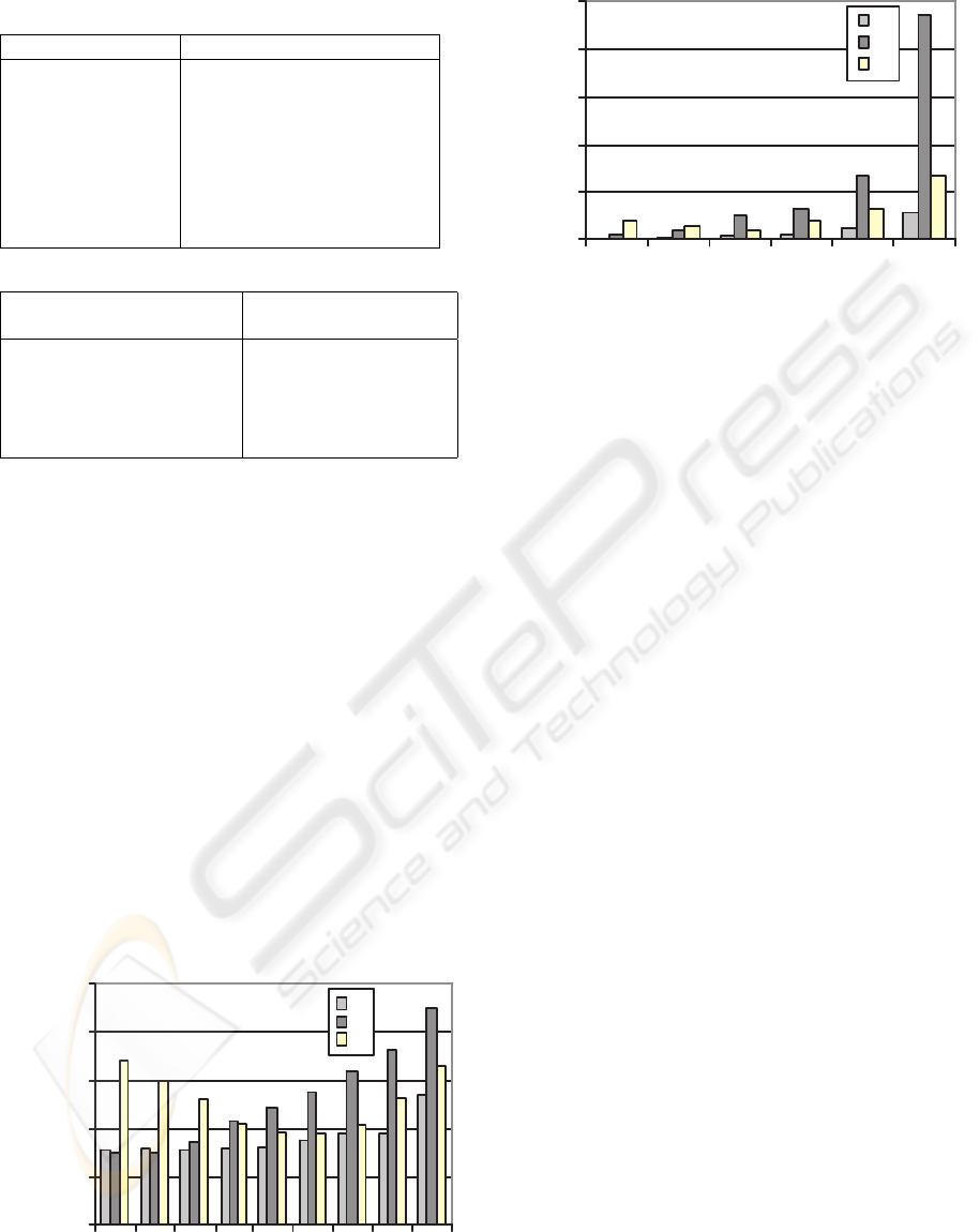
Table 1: Grouping Schemes.
Grouping Scheme comments
data-centric (dc) groups generated with the
grid partitioning scheme
client-centric (cc) widely employed, creates
one group for each client
giant-group (gg) eliminates duplicate update
storage by storing updates
for all the clients in a
single group
Table 2: Parameter values for experiments.
Parameter Description Values (control values
in{})
Clients 1, 2, 5, 10, {50}, 100,
200, 400, 800
u
rate
(update/client/min) 0.1, 0.5, {1}, 2, 4, 8
Pruning interval, T (min) {60}
Percent of replication (p) {10}
Figure 6 shows the effect of varying client pop-
ulation on per-client refresh time. Scheme gg fares
poorly with low population because it generates and
stores update logs for a significant portion of database
that is not subscribed to. Client-centric scheme per-
forms well with very low client population, but with
the increase in client population the refresh time in-
creases drastically because of duplicate update stor-
age (once for every relevant client) and pruning over-
head for the duplicate updates. On the other hand, as
scheme gg stores updates only once, it doesn’t suf-
fer from storage and pruning overhead. Hence, per-
client refresh time doesn’t degenerate severely for this
scheme. However, for every client the whole update
log file should be retrieved that contains significant
portion of irrelevant updates for that client. As is ev-
ident from the figure, within the given range of client
population, the refresh time of scheme dc is opti-
mal except for the very low client population, where
client-centric approach predominates.
1
10
100
1000
10000
100000
1 2 5 20 50 100 200 400 800
Clients
Refresh Time/Client (ms)
dc
cc
gg
Figure 6: Per-client refresh time (ms) with varying client
population (y-axis is in log scale).
0
500
1000
1500
2000
2500
0.1 0.5 1 2 4 8
Update-rate/client
Refresh Time/client (ms)
dc
cc
gg
Figure 7: Per-client refresh time (ms) with varying work-
load, u
rate
(updates/client/min) (y-axis is in log scale).
Figure 7 shows the effect of variation of per-client
update arrival rate upon per-client refresh time. In this
scenario, the dc approach achieves significant savings
on refresh time over other methods.
7 CRITICAL EVALUATION
We propose an approach to update propagation that
doesn’t assume the inherent data organization of the
database. We show that efficient algorithms are pos-
sible for designing and maintaining datagroups as
well as mapping clients to groups. For both sin-
gle and multiple attribute replication, mapping new
clients to the datagroups is simple. Maintenance of
the datagroups, with the change in ICDB configura-
tion, doesn’t require frequent recomputation of data-
groups from the scratch. So, it is possible to main-
tain the datagroups incrementally. If the change in the
configuration is not drastic, we only have to modify a
few datagroups locally. Moreover, in case of multi-
ple RS-attributes, as the splitting is carried on each
axis independently, the computational complexity of
datagroup formation only increases linearly with the
increase in number of RS-attributes (i.e., dimension
of the grid array).
8 CONCLUSION AND FUTURE
WORKS
In this paper, we offer a computationally efficient
solution to scalable update propagation problem in
ICDB. Based on a cost model, we construct and main-
tain datagroups by simply splitting each path graph
(one for each RS-attribute) independently along few
selected edges. We address the problem of duplicate
update propagation in ICDB and propose a solution
ICEIS 2006 - DATABASES AND INFORMATION SYSTEMS INTEGRATION
20

that provides a little per-client processing. We in-
troduce the notion of pruning interval to remove the
unnecessary updates from the log files and thus save
both retrieval time and disk space. The replica for-
mation time can be minimized by organizing the data
as a grid file, as only the necessary grid blocks can
be fetched from the disk without the need to scan (in
worst case) the whole data file. Our work on ICDB
is ongoing. Currently we are working on building an
analytical model for estimating the savings in terms
of data volume and network time resulting from elim-
inating duplicate update propagation. Also, we are
working on a scheme for vertical partitioning the at-
tributes of a relation to reduce the updates that need to
be propagated to the clients. The objective here is to
have one consistent model for datagroup design that
includes vertical partitioning of a relation.
REFERENCES
Badrinath, B. R. (1999). An architecture for mobile Data-
bases. Department of Computer Science Technical
Report DCS-TR-531, Rutgers University, New Jersy.
Bernstein, P. A., Hadzilacos, V., and Goodman, N. (1987).
Concurrency Control and Recovery in Distributed
Database Systems. Addison Wesley, Reading, Massa-
chusetts.
Breitbart, Y. and Korth, H. F. (1997). Replication and con-
sistency: Being lazy helps sometimes. Proceedings of
ACM SIGMOD.
Chakraborty, L., Singh, A., and Naik, S. (2002). An Ef-
ficient Vertical Partitioning Algorithm for Partially
replicated Database in Disconnected Environment.
Report, Network Programming Lab, Dept. of Electri-
cal & Computer Engineering, University of Waterloo.
Chakraborty, L., Singh, A., and Naik, S. (2004). Pruning
update log files in intermittently connected databases.
proceedings of the Third International Workshop on
Wireless Information Systems, pages 63–72.
Daudjee, K. and Salem, K. (2004). Lazy database replica-
tion with freshness gaurantees. Proceedings of ICDE.
Davidson, S. B. (1984). Optimism and consistency in par-
titioned distributed database systems. ACM Transac-
tions on Database Systems, 9(3):456–481.
Demers, A., Greene, D., Hauser, C., Irish, W., Larson, J.,
Shenker, S., Sturgis, H., Swinehart, D., and Terry, D.
(1987). Epidemic algorithms for replicated database
maintenance. Proceedings of the Sixth Symposium on
Principles of Distributed Computing, pages 1–12.
Demers, A., Peterson, K., Spreitzer, M., Theimer, M., and
Welch, B. (1994). The bayou architecture: Support
for data sharing among mobile users. Proceedings of
Mobile Computing Systems and Applications.
Diener, A. R., Bragger, R., Dudler, A., and Zehnder, C. A.
(1985). Replicating and allocating data is a distributed
database system for workstations. ACM Symposium
on Small Systems, pages 5–9.
Gray, J., Holland, P., O’Neil, P., and Shasha, D. (1996). The
dangers of replication and a solution. Proceedings of
ACM SIGMOD, pages 173–182.
Gross, J. and Yellen, J. (1999). Graph theory and its appli-
cation. CRC Press, Boca Raton.
Gupta, A. and Mumick, I. S. (1995). Maintenance of ma-
terialized views: Problems, techniques, and applica-
tions. IEEE Data Engineering Bulletin, 18:3–18.
Mahajan, S., Donahoo, M., Navathe, S., and Ammar, M.
(1998). Grouping techniques for update propagation
in termittently connected databases. Proceedings of
Fourteenth International Conference on Data Engi-
neering, pages 45–53.
Ng, S. (1998). Advances in disk technology: performance
issues. IEEE Computer, 31(5):75–81.
Nievergelt, J. and Hinterberger, H. (1984). The grid file: An
adaptable, symmetric multiple key file structure. ACM
transactions on Database Systems, 9(1):38–71.
Pacitti, E., Minet, P., and Simon, E. (1999). Fast algorithms
for maintaining replica consistency in lazy master
replicated databases. Proceedings of the Twenty fifth
International Conference on Very Large Data Bases,
pages 126–137.
Pacitti, E. and Simon, E. (2000). Update propagation strate-
gies to improve freshness in lazy master replicated
databases. VLDB Journal, 8:305–318.
Peterson, K., Spreitzer, M. J., Terry, D. B., Theimer, M. M.,
and Demers, A. J. (1997). flexible update propaga-
tion for weakly consistent replication. Proceedings
of Sixteenth ACM Symposium on Operating Systems
Principles, pages 288–301.
Rabinovich, M., Gehani, N., and Kononov, A. (1996). Scal-
able update propagation in epidemic replicated data-
bases. Prococeedings of International Conference on
extending database technology.
Satyanarayanan, M., Kistler, J. J., Mummert, L. B., Ebling,
M. R., Kumar, P., and Liu, Q. (1993). Experience
with disconnected operation in a mobile environment.
Proceedings of USENIX Symposium on Mobile and
Location-Independent Computing.
Tanenbaum, A. S. (1996). Modern Operating Systems.
Prentice Hall.
Yee, W. G., Donahoo, M. J., Omiecinski, E., and Navathe,
S. (2001). Scaling replica maintenance in intermit-
tently synchronous mobile databases. Proceedings of
CIKM, pages 450–457.
SCALABLE UPDATE PROPAGATION IN PARTIALLY REPLICATED, DISCONNECTED CLIENT SERVER
DATABASES
21
