SEMANTIC ALIGNMENT OF BUSINESS PROCESSES
Saartje Brockmans, Marc Ehrig, Agnes Koschmider,
Andreas Oberweis, Rudi Studer
Institute AIFB, Universit
¨
at Karlsruhe (TH)
D-76128 Karlsruhe, Germany
Keywords:
Business Processes, Petri nets, Ontologies, OWL DL, UML.
Abstract:
This paper presents a method for semantically aligning business processes. We provide a representation of
Petri nets in the ontology language OWL, to semantically enrich the business process models. On top of
this, we propose a technique for semantically aligning business processes to support (semi)automatic inter-
connectivity of business processes. This semantic alignment is improved by a background ontology modeled
with a specific UML Profile allowing to visually model it. The different parts of our proposal, which reduces
communication efforts and solves interconnectivity problems, are discussed.
1 INTRODUCTION
Inter-organizational business collaborations bring up
synergy effects and can reduce enterprise risks. How-
ever, the insufficient integration of enterprises ham-
pers collaborations because of different interpreta-
tions of terms’ meanings. Furthermore, the integra-
tion of collaborating business partners into one sin-
gle value creation chain requires flexible business pro-
cesses to reduce cost and shorten time caused by the
integration. The interconnectivity of business pro-
cesses can fail due to company specific vocabularies
even if business partners share similar demands.
For modeling business processes, we are utilizing
Petri nets (Reisig and Rozenberg, 1998), which are
suitable for modeling, simulating, and analysing busi-
ness processes. Due to the formal foundation of Petri
nets, the syntactical interconnectivity problems can be
solved. However, the missing semantic representation
renders the integration of business processes. Misun-
derstandings appear due to homonyms, synonyms or
different abstraction levels. So far, semantic repre-
sentation of business objects and activities remains a
challenge and has to be addressed by research.
The aim of our work is to provide semantic in-
terconnectivity of interorganizational business pro-
cesses, even if there exist ambiguity issues caused by
different interpretations of data. For this, we propose
an approach that enables semantic alignment (defin-
ing involved objects in some mutual relationship) of
Petri nets by translating Petri nets into an ontology de-
fined with the Web Ontology Language (OWL (Dean
and Schreiber, 2003)). Further, to improve the align-
ment, we model a background ontology using the
Unified Modeling Language (UML) (Fowler, 2004),
where the UML-elements can be translated to OWL
elements. By extending existing ontology alignment
techniques we show that it is possible to achieve our
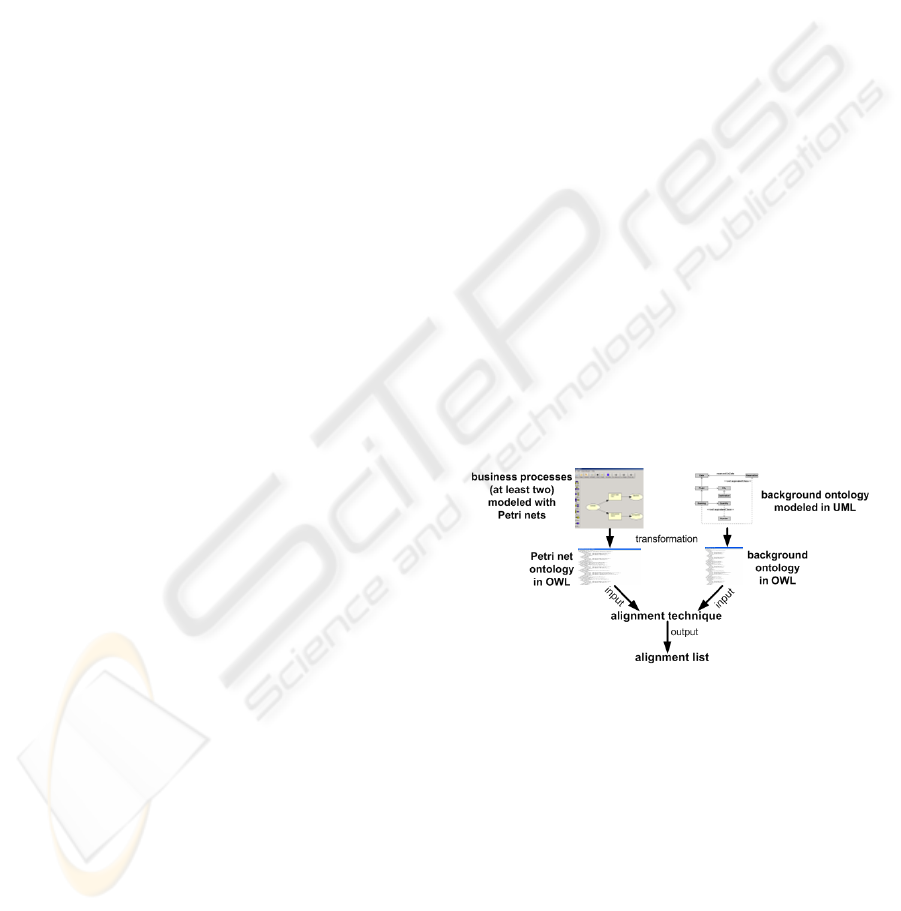
goal. An overview of the process described in this
paper is depicted in Figure 1.
Figure 1: Semantic Alignment of Business Processes.
Firstly, in this paper we will recall the notions of
Petri nets, ontologies, UML and alignment. Secondly,
we will describe an approach for representing Petri
nets with OWL, on how to model ontologies using
UML, and an ontology alignment technique to over-
come ambiguity issues. Finally, we will give a con-
clusion and an outlook on future work.
2 FOUNDATIONS
In this section Petri nets, ontologies and UML2 will
be introduced. Further, we define the term alignment.
191
Brockmans S., Ehrig M., Koschmider A., Oberweis A. and Studer R. (2006).
SEMANTIC ALIGNMENT OF BUSINESS PROCESSES.
In Proceedings of the Eighth International Conference on Enterprise Information Systems - ISAS, pages 191-196
DOI: 10.5220/0002495601910196
Copyright
c
SciTePress
2.1 Petri Nets
Petri nets are a accepted graphical language for the
specification and simulation of information system
behaviour (Reisig and Rozenberg, 1998). Formally,
a Petri net is a directed bipartite graph with nodes
(places and transitions represented as circles and as
boxes) and arcs (flow relations as directed arcs be-
tween places and transitions) and can be described by
the tripel N = (P, T, F ), where P is a set of Places, T
a set of Transitions and F ⊆ (P × T ) ∪ (T × P ).
In contrast to elementary Petri nets, in high-level
Petri nets (e.g. Predicate/Transition nets (Genrich and
Lautenbach, 1981)) tokens are distinguishable and
allow to describe objects with individual properties.
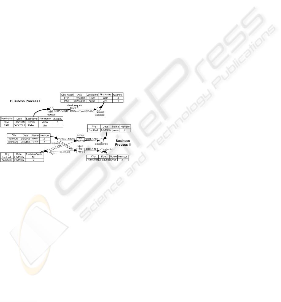
Figure 2 illustrates two Predicate/Transiton nets (Pr/T
nets) for flight reservation processes. After sending a
request, the request will be checked (Process I) and
in Process II request and f light data are required to
accept or reject the flight request. In Figure 2, the
business partners use different terms with the same
meaning. Business partner I, e.g., utilizes ”Quantity”
and business partner II ”Number”.
Figure 2: Modeling business processes with Pr/T nets.
A strict Predicate/Transition net
1
is a tuple PrT =
(P, T, F, Ψ, AI, T I, M
0
) satisfying the following
conditions: (i) (P, T, F ) is a net where P is a set of
predicates, T a set of transitions and F a set of arcs;
(ii) Ψ = (D, F T, P R) is a structure consisting of a
set of individuals D, a set of functions F T defined
for D and a set PR of predicates over D; (iii) the arc
inscription AI assigns to all elements of F a formal
sum of n-tuples of variables where n is the arity of
the predicate connected to the arc; (iv) T I assigns to
elements of T a transition inscription where variables
occurring in a transition box have to occur at an adja-
cent arc; (v) M
0
is a marking of the predicates with
sets of constant individual tuples, where the arity must
correspond to the arity of the respective predicate.
The interconnectivity of business processes depicted
in Figure 2 requires a common interpretation of
1
In strict Pr/T nets, duplicate tuples in a predicate are
not allowed.
data represented in places and of labeled transitions.
Furthermore, in order to enable (semi-) automated
semantic interconnectivity, a structured and well-
understood format of Petri nets would be useful.
2.2 Ontologies
Terms and descriptions used in business processes
may differ from company to company. By formal de-
scriptions in a shared ontology, all business partners
would have a common understanding of the terms’
domain. An ontology is defined through the do-
mains concepts and properties, both arranged in a sub-
sumption hierarchy, instances of specific concepts and
properties and axioms to infer new knowledge from
already existing one. In 2004, the World Wide Web
Consortium (W3C) finished its standardization work
on the Web Ontology Language (OWL), thus laying
the foundations for a wide-spread use of ontologies
in business. With OWL, relevant concepts of the do-
main (its terminology), their properties and instances
(the world description) can be defined.
2.3 Unified Modeling Language
The Unified Modeling Language (UML) is a fam-
ily of graphical notations, backed by a single meta-
model, that help in expressing domain models. The
UML defines a notation and a meta-model where the
meta-model specifies the concepts of the language.
The UML is a well-established and popular language
standardized and driven by the Object Management
Group. One characteristic of UML2, which is an
extension of UML, is that it is independent of the
methodology which is used for analysis and design.
Regardless of the methodology that one uses, one can
use UML2 to express the results. UML2 defines thir-
teen types of diagrams, of which one, the Class Di-
agram, is the most relevant for our work. A Class
diagram gives an overview of a domain by showing
its concepts and their attributes as well as the rela-
tionships among them. Class diagrams display which
elements interact but not what happens when an inter-
action takes place.
2.4 Alignment
Given two structures (e.g., ontologies or Petri nets),
aligning one structure with another one means that
for each entity (e.g., concepts and relations, or places
and transitions) in the first structure, one tries to find
a corresponding entity, which has the same intended
meaning, in the second structure (Klein, 2001). An
alignment therefore represents one-to-one equality.
We define an alignment function, align, based on
the vocabulary, E, of all entities e ∈ E and based
ICEIS 2006 - INFORMATION SYSTEMS ANALYSIS AND SPECIFICATION
192

on the set of possible structures, S, as a function:
align : E × S × S → E. We leave out S when it
is evident and write align(e) = f instead. For some
entities, no corresponding entity might exist.
3 SEMANTIC ALIGNMENT OF
PETRI NETS
In business relationships, a commonly agreed vocab-
ulary can usually not be postulated. To solve ambi-
guity issues caused by the use of different terms and
to support (semi-)automated system cooperation, we
start by describing an ontology based annotation for
Petri nets. We will further show that ontologies can be
modeled visually using UML tools. Finally, we will
make use of adapted ontology alignment techniques
to solve ambiguity issues of Petri nets.
3.1 Modeling Petri Nets in OWL
By combining Petri nets with OWL, our approach
provides flexibility and interoperability for business
processes in order to enable semantical information
exchange.
Our Pr/T net ontology consists of the concepts
P etriNet (for all possible Petri nets N = (P, T, F )),
T ransition (for all Transitions of T ), P lace (for all
Places of P ), FromP lace and T oP lace (for all arcs
of F
r
and F
w
), LogicalConcept (for all transition
inscriptions of T I), IndividualDataItem (for all
predicates P R), Delete and Insert (for arc inscrip-
tions AI with sets of variable tuples). Furthermore,
our Pr/T net ontology contains the classes Attribute
(for all functions of F T ), V alue (for all subsets of
D
1
× . . . × D
n
), Condition (for occurrence condi-
tion) and Operation (for occurrence operation).
With these concepts, we specify properties between
concepts as defined in the ontology of Figure 3.
For example, the concept P etriNet is defined by
a property hasNode with cardinality ≥ 1 and range
transition or place (T ransition t P lace) and the
property hasArc with the cardinality ≥ 0 and range
FromPlace or ToPlace (F romPlace t T oP l ace).
The extraction of descriptions of business pro-
cesses and the mapping to the Pr/T net ontology is
being carried out automatically and is not directly vis-
ible to the modeler. After modeling business pro-
cesses, the models can be exported to OWL syntax
and afterwards be sent to the respective business part-
ners. The excerpted OWL serialisation of Business
Process II of Figure 2 is depicted in Figure 4 where
e.g. label of the place flight is borded my the ele-
ment < petri : P lace/ > with an URI pointing to
namespace of the Pr/T net ontology.
P etriNet ≡ ≥ 1hasN ode.(T ransition t P lace)
u hasArc.(F romP lace t T oP lace)
T ransition ≡
placeRef.P laceu = 1haslogicalConcept.LogicalConcept
P lace ≡
transRef.T ransitionu = 1hasM arking.IndividualDataItem
F romP lace ≡ ≥ 1hasInscription.Delete u ∃hasN ode.P lace
T oP lace ≡ ≥ 1hasInscription.Insert u ∃hasNode.T r ansition
LogicalConcept ≡
= 1hasConditon.Conditiont = 1has.Operation.Operationu
∃hasAttribute.IndividualDataItem
IndividualDataItem ≡ ≥ 1hasAttribute.Attribute
Delete ≡ ∀hasAttribute.IndividualDataItem
Insert ≡ ∃hasAttribute.IndividualDataItem
Atrribute ≡ ≤ 1hasV alue.V alue
V alue w hasRef.V alue
Condition ≡ f orall(string) t exists(string) t and(string)
Operation ≡ f unction(string)
Figure 3: Pr/T net ontology.
<petri:Place rdf:ID="#flight">
<petri:hasMarking>
<petri:IndividualDataItem rdf:ID="R_flight">
<petri:hasAttribute rdf:resource="#City"/>
<petri:hasAttribute rdf:resource="#Date"/>
<petri:Attribute rdf:resource="#AvailableSeats"/>
</petri:hasAttribute>
</petri:IndividualDataItem>
</petri:hasMarking>
</petri:Place>
Figure 4: Part of the OWL serialization of Process II.
The OWL serialisation of several Pr/T nets can be
interconnected afterwards. However, before intercon-
nection correspondences by utilizing alignment tech-
niques have to be found. A background ontology im-
proves the semantic alignment.
3.2 Visually Modeling the
Background Ontology
As part of our approach, we provide a background on-
tology to improve the semantic alignment of business
processes. However, for modeling the ontologies, we
will provide a visual syntax, namely using UML2. A
tool provides an automatic translation from the visual
model to the OWL syntax.
It has been shown (Schnotz, 2002) that manual
modeling causes a lot of errors, including typing mis-
takes as well as structural mistakes. Visual syntaxes
are shown to bring many benefits that simplify con-
ceptual modeling. Like as for other modeling pur-
poses, visual modeling of ontologies decreases syn-
tactic errors and increases readability. It makes mod-
eling and use of ontologies easier and faster, espe-
SEMANTIC ALIGNMENT OF BUSINESS PROCESSES
193
cially if tools are user friendly and appropriate mod-
eling languages are applied. Currently, visual model-
ing of ontologies is predominantly done with form- or
tree-based tools, which unfortunately have shortcom-
ings as not easily showing relationships.
We use UML2 Class Diagrams for visually model-
ing the background ontology. Since UML2 is a well-
known language, it provides an agreed format and
covers a broad community, we can benefit a lot from,
e.g., reusing existing tools. The chance that someone
modeling business processes is familiar with UML2
is much higher than with logic for manually writing
an OWL-ontology.
Our means to define the background ontology, as
well as other possible ontologies, using UML2, has
two main components: an Ontology Definition Meta-
model and a UML Ontology Profile. The Ontology
Definition Metamodel defines a metamodel for on-
tologies. This metamodel is built on the Meta Ob-
ject Facility (OMG, 2002), a model driven integration
framework for defining, manipulating as well as inte-
grating metadata and data in a platform independent
way. Shortly, it allows to define modeling languages.
We defined an Ontology Definition Metamodel for
OWL using an intuitive notation, both for users of
UML2 and OWL. A metamodel for a language that
allows the definition of ontologies naturally follows
from the modeling primitives offered by the ontology
language.
The second component we need, is a UML profile,
determining a visual UML syntax to model ontolo-
gies. We provide a UML profile that is faithful to both
UML2 and OWL, with a maximal reuse of UML2
features and OWL features. Since the UML profile
mechanism supports a restricted form of metamodel-
ing, our proposal contains a set of extensions and con-
straints to the UML metamodel. This tailors UML2
such that models instantiating the Ontology Defini-
tion Metamodel can be defined. (Brockmans et al.,
2004). Figure 5 shows an excerpt of the background
ontology for the domain of flight booking, modeled
using a UML tool.
Figure 5: Part of the background ontology modeled in
UML.
Due to this easy-to-use creation of ontologies, we
expect business to make use of ontologies to a higher
degree than today. This is especially the case since an
immediate benefit can be seen when integrating ex-
isting business processes models in one organization
with business process models in another organization.
We explain this integration of business processes in
the following section.
3.3 Aligning Petri Nets
In this section, we show that it is possible to se-
mantically align Petri nets by making use of existing
technology for ontology alignment (Ehrig and Staab,
2004) based on the similarity of the individual ele-
ments and their structure. Using semantic features,
we expect our approach to be superior to existing,
only syntax-based, approaches for alignment of Petri
nets. Further, we seamlessly add the created domain
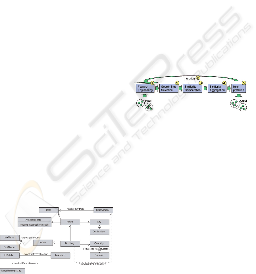
ontology as background knowledge. Below, we de-
scribe the different steps of the process (Figure 6).
Figure 6: Ontology alignment process.
Input: With the common OWL representation of
Petri nets and background ontology, we can focus on
semantic alignment, thus only need to change the se-
mantic basis of the already existing process.
1. Feature Engineering: As a first step, we need
to identify those features which may be used to com-
pare Petri net elements and determine whether the el-
ements are the same. We refer to Table 1 for a list of
relevant features as determined by an expert.
2. Search Step Selection: Next, we need to decide
which elements to compare. The standard approach is
to use a complete approach, i.e., each element of the
one ontology is compared with each element of the
same type in the other ontology.
3. Similarity Computation: The similarity com-
putation is straightforward. Table 1 shows for each
entity type a list of corresponding features and the
similarity measures that are needed to compare them.
One can rely on existing measures for comparisons of
strings, objects, or sets of objects (Ehrig et al., 2005).
4. Similarity Aggregation: The mentioned table of
features and similarities is extended by a weight for
similarity aggregation. Only a basic linear weighting
scheme has been applied at this point, but more com-
plex aggregations are conceivable.
ICEIS 2006 - INFORMATION SYSTEMS ANALYSIS AND SPECIFICATION
194

Table 1: Features and similarity measures for Petri nets.
Comparing Feature Measure Weight
Places name string sim. 1
Attribute/Value set sim. 1
predecessor set sim. 0.5
successor set sim. 0.5
Attributes name string sim. 1
sibling Attribute set sim. 1
Values set sim. 1
Place object sim. 0.5
Values name string sim. 1
Attribute object sim. 1
Value reference object sim. 1
Transitions name string sim. 1
ToPlace set sim. 1
FromPlace set sim. 1
5. Interpretation: We apply a fixed threshold to the
aggregated similarities. Every value above the thresh-
old is interpreted as an alignment of the Petri net ele-
ments, every one below does not lead to an alignment.
Further, we allow user interaction to increase the qual-
ity of these alignment results by presenting the most
uncertain alignments.
6. Iteration: The alignment of element pairs affects
the similarity of neighboring pairs. This is propagated
through iteration.
Output: The output is a list of aligned places, at-
tributes, values and transitions with their correspond-
ing confidence (the aggregated similarity values).
We illustrate this process along the Petri nets in
Figure 2. Possible candidate alignments would be the
pairs of places , transitions, attributes, or values, e.g.,
(sent request, request) or (frankfurt, FRA). We will
now exemplary do the comparison for the attribute
pair (Quantity, Number). The names are obviously
different, thus resulting in sim
name
= 0.0. How-
ever, their sibling attributes (Destination, Date, Last-
Name and FirstName) and values (3,1 and 2,3) are
very similar (sim
siblings
= 1.0, sim
v alues
= 0.5),
and also the linked places (sent request and request)
are similar (sim
place
= 0.5). In fact, the back-
ground ontology helps us to determine that the City
attributes actually mean the same, despite the differ-
ent values (frankfurt, paris and FRA, PAR). All these
similarities lead to an aggregation of sim
ag g
= 0.5.
With a given threshold of t = 0.5, we can infer
align(Quantity) = N umber; Quantity in Petri net
1 is aligned with Number of Petri net 2. An excerpt
of further results is depicted in Table 2. These results
have directly been taken from the implementation of
the approach described in this paper.
A good result would include most correct align-
ments and only return a low number of false align-
ments. Meeting the current lack of semantic align-
ment approaches for Petri nets, a good approach is
Table 2: Results of Petri net alignment.
Petri net 1 Petri net 2 Similarity Alignment
Destination City 1.0 yes
frankfurt FRA 1.0 yes
send request request 0.8 yes
Quantity Number 0.5 yes
check request accept flight 0.4 no
Smith meier 0.2 no
any approach providing more alignments of entities
than those which have identical labels. Our ap-
proach provides this and thus releases the human user
from strenuously manually searching the Petri nets
for alignments. Despite incorrect alignments such an
approach might also produce, it can strongly support
users in creating alignments between Petri nets.
The semantic alignment method presented in this
paper has been tested on several business processes
(Petri nets with more than 20 places and transitions).
Currently, we still have to manually verify the auto-
mated proposition of alignment candidates. However,
we are working to automate this, too.
4 RELATED WORK
For modeling business processes, several languages
have been published such as BPMN, BPEL (Andrews
et al., 2003) and EPC (Scheer, 1998). All those meth-
ods do not provide integrated concepts to model, ana-
lyze and simulate inter-organizational business pro-
cesses. For modeling complex dynamic systems,
high-level Petri nets proved to be suitable. In (Lenz
and Oberweis, 2003) syntactic composition problems
of inter-organizational business processes with Petri
nets are discussed. However, the semantic alignment
and composition problems of Petri nets have not been
addressed by research, yet.
Visual syntaxes, as we use for the background on-
tology, are shown to bring many benefits that simplify
conceptual modeling. Several examples exist in prac-
tice, like the Entity Relationship Model (Chen, 1976)
for database modeling or the Unified Modeling Lan-
guage (Fowler, 2004) for software design. Also in
the field of Knowledge Representation, several for-
malisms already exist, e.g. Conceptual Graphs (Sowa,
1992), Topic Maps (ISO/IEC, 1999) or the particular
visual notation for CLASSIC Description Logic. For
the moment, visual modeling of ontologies is predom-
inantly done with form or tree based tools. Although
this is already a good progress, it is still not as visual
as it could be or as one would like to have it.
The problem of ontology alignment has been dis-
cussed in the Semantic Web community for several
years. The PROMPT-suite (Noy and Musen, 2003)
SEMANTIC ALIGNMENT OF BUSINESS PROCESSES
195

uses labels and to a certain extent the structure of
ontologies. (Doan et al., 2003) use a general learn-
ing approach in their tool GLUE which requires a big
base of similar instances. In contrast to most existing
(quality-focused) approaches (Ehrig and Staab, 2004)
present an efficiency-optimized approach. Whereas
related work on individual aspects of this work exists,
we are not aware of efforts making use of ontologies
and their alignment techniques for Petri nets.
5 CONCLUSION AND OUTLOOK
The rapid growth of electronic markets’ activities de-
mands flexibility and automation of involved systems
in order to facilitate the interconnectivity of business
processes and to reduce communication efforts. In
this paper we described an approach of aligning OWL
serializations of Petri nets by (semi-) automatically
finding mutual relationships. To improve this align-
ment, we utilized a background ontology modeled us-
ing UML.
The combination of Petri nets with OWL provides
a basis for further research work. As business pro-
cesses may be modeled coarse grained or fine grained
with a lot of hierarchy levels, we are developing algo-
rithms to compute the semantic similarity of business
processes as a whole to identify their overlap. Finally,
to interconnect disjoint business processes, we have to
define a suitable connection point for coupling several
business processes.
ACKNOWLEDGEMENTS
Research reported in this paper has been partially fi-
nanced by the EU in the IST project SEKT (IST-2003-
506826) and the German Research Foundation (DFG)
in scope of the Graduate School Information Manage-
ment and Market Engineering.
REFERENCES
Andrews, T. et al. (2003). Business Process
Execution Language for Web Services.
www.ibm.com/developerworks/library/ws-bpel.
Brockmans, S., Volz, R., Eberhart, A., and Loeffler, P.
(2004). Visual Modeling of OWL DL Ontologies us-
ing UML. In (van Harmelen et al., 2004), pages 198–
213.
Chen, P. (1976). The entity-relationship model–toward a
unified view of data. ACM Transactions on Database
Systems, 1(1):9–36.
Dean, M. and Schreiber, G. (2003). Web Ontology Lan-
guage (OWL) Reference Version 1.0. Technical re-
port, World Wide Web Consortium (W3C).
Doan, A., Domingos, P., and Halevy, A. (2003). Learning
to match the schemas of data sources: A multistrategy
approach. VLDB Journal, 50:279–301.
Ehrig, M., Haase, P., Hefke, M., and Stojanovic, N. (2005).
Similarity for ontologies - a comprehensive frame-
work. In Bartmann, D. et al., editors, Proceedings
of the 13th European Conference on Information Sys-
tems (ECIS), Regensburg, Germany.
Ehrig, M. and Staab, S. (2004). QOM - quick ontology
mapping. In (van Harmelen et al., 2004), pages 683–
696.
Fowler, M. (2004). UML Distilled Third Edition. Addison-
Wesley.
Genrich, H. J. and Lautenbach, K. (1981). System mod-
elling with high level petri nets. Theoretical Computer
Science, (13):109–136.
ISO/IEC (1999). Topic Maps: Information Technol-
ogy – Document Description and Markup Languages.
ISO/IEC standard 13250:2000.
Klein, M. (2001). Combining and relating ontologies: an
analysis of problems and solutions. In G
´
omez-P
´
erez,
A. et al., editors, Proceedings of Workshop on On-
tologies and Information Sharing at the 17th Inter-
national Joint Conference on Artificial Intelligence
(IJCAI-2001), Seattle, WA, USA.
Lenz, K. and Oberweis, A. (2003). Interorganizational
business process management with XML nets. In
Ehrig, H. et al., editors, Petri Net Technology for
Communication-Based Systems, Advances in Petri
Nets, volume 2472 of Lecture Notes in Computer Sci-
ence, pages 243–263. Springer.
Noy, N. F. and Musen, M. A. (2003). The PROMPT suite:
interactive tools for ontology merging and mapping.
International Journal of Human-Computer Studies,
59(6):983–1024.
OMG (2002). Meta Object Facility (MOF) Specification.
Technical report, Object Management Group (OMG).
Reisig, W. and Rozenberg, G. (1998). Lectures on Petri
Nets: Basic Models, volume 1491 of Lecture Notes in
Computer Science. Springer, 1 edition.
Scheer, A.-W. (1998). ARIS - Business Process Modeling.
Springer, Berlin et al., 2 edition.
Schnotz, W. (2002). Wissenserwerb mit Texten, Bildern
und Diagrammen. Belz, PVU, Weinheim, third, com-
pletely revised edition.
Sowa, J. F. (1992). Conceptual Graphs Summary. In Ek-
lund, P. et al., editors, Conceptual Structures: Current
Research and Practice, page 352.
van Harmelen, F. et al., editors (2004). Proceedings of the
3rd International Semantic Web Conference (ISWC-
2004), volume 3298 of Lecture Notes in Computer
Science, Hiroshima, Japan. Springer.
ICEIS 2006 - INFORMATION SYSTEMS ANALYSIS AND SPECIFICATION
196
