
A KNOWLEDGE-BASED REVERSE DESIGN SYSTEM
FOR DECLARATIVE SCENE MODELING
Vassilios Golfinopoulos
Laboratoire Méthodes et Structures Informatiques – MSI, Faculté des Sciences, Université de Limoges
83, rue d’Isle, 87060 Limoges cedex, France
Technological Education Institute of Athens, Department of Computer Science,
Ag.Spyridonos St., 122 10 Egaleo, Greece
Vassilios Stathopoulos, George Miaoulis
Technological Education Institute of Athens, Department of Computer Science,
Ag.Spyridonos St., 122 10 Egaleo, Greece
Dimitri Plemenos
Laboratoire Méthodes et Structures Informatiques – MSI, Faculté des Sciences, Université de Limoges
83, rue d’Isle, 87060 Limoges cedex, France
Keywords: Declarative Modeling, Knowledge-Based Systems, Reverse Design, Computer-Aided Design.
Abstract: Declarative modeling allows the designer to describe a scene without the need to define the geometric
properties. The MultiCAD architecture implements the declarative forward design, accepting a declarative
description and generating a set of geometric solutions that meet the description. The aim of the presented
work is to settle the reverse design process through the RS-MultiCAD component, a knowledge-based
system, in order to extend MultiCAD declarative conception cycle to an automated iterative process. The
RS-MultiCAD receives a selected geometric solution, which is semantically understood, permits the
designer to perform geometric and topological modifications on the scene, and results a declarative
description which embodies the designer modifications. That declarative description leads to more
promising solutions by reducing the initial solution space.
1 INTRODUCTION
Declarative modeling is an approach (Lucas, 1989)
that allows the designer to describe a desired scene
without the need to define the geometric properties
overcoming CAD applications drawbacks. A set of
solutions are generated that meet the initial
description. A special approach of the declarative
modeling is declarative modeling by hierarchical
decomposition (Plemenos, 1991), which gives the
user the ability to describe a scene by top-down
decomposition at different levels of abstraction. The
objective of this method is to remedy the
disadvantages of the traditional geometric modeling
by allowing the description of a scene by its
properties, which can be imprecise and incomplete.
More accurately the declarative modeling makes
possible to indicate the properties, which verify the
desirable scene in several levels of detail allowing
thus a top-down design.
MultiCAD architecture (Miaoulis, 1996),
(Miaoulis, 1998) is an intelligent multimedia CAD
system, liberated of geometrical inflexibility that
accepts a declarative description of a scene and
produces a set of solutions that meet the description
itself.
Our goal is to implement the declarative reverse
design by constructing a new declarative description
from an initially selected geometric solution which
has been modified by the designer in order the
design process to become iterative automatically
until the system produces the most desirable
82
Golfinopoulos V., Stathopoulos V., Miaoulis G. and Plemenos D. (2006).
A KNOWLEDGE-BASED REVERSE DESIGN SYSTEM FOR DECLARATIVE SCENE MODELING.
In Proceedings of the Eighth International Conference on Enterprise Information Systems - AIDSS, pages 82-90
DOI: 10.5220/0002497200820090
Copyright
c
SciTePress

solutions. The new component is placed within the
MultiCAD architecture. The introduction of the new
component was first discussed in (Golfinopoulos,
2005) and the current work presents the functionality
that underlies the RS-MultiCAD prototype
component.
1.1 Declarative Conception Cycle
The declarative scene modeling is based on the
declarative conception cycle, which consists of three
sequential functional phases (Plemenos, 1995). The
first is the scene description phase, where the
designer describes how he perceives the scene by
specifying properties of the scene or leaving them
ambiguous. The second is the generation phase,
where the generator inputs the declarative model and
produces a set of solutions that meet the description
of the desired scene. The third is the solution
understanding phase, where the scene solutions are
visualized through a geometric modeler.
1.2 MultiCAD Architecture
The design environment of MultiCAD features a
rich set of modules. These include alternative
modules for solution generation using CSP
(Plemenos, 1997) or genetic algorithms (Vassilas,
2002), (Makris, 2005) as well as modules
responsible for introducing architectural knowledge
(Ravani, 2003), representation of architectural styles
(Makris, 2003), collaborative design (Golfinopoulos,
2004), and intelligent user profile (Plemenos, 2002),
(Bardis, 2005).
MultiCAD incorporates an object-relational
database (Miaoulis, 2000), which consists of five
logical inter-connected databases. The scene
database is supporting information describing the
scene models. The multimedia database is
containing all types of documents related to the
project. The knowledge base is containing all the
necessary information about type of objects, their
properties along with their relations. The project
database is manipulating with data concerning
planning, financial and other special aspects of each
project and finally the concept database (Ravani,
2004) is storing concepts representations.
The scene database is configured following the
Scene Conceptual Modeling Framework (Miaoulis,
2000). The description contains objects defined by
their properties, simple or generic ones, as well as
group of simple objects with properties in common.
Besides, the description contains three types of
relations between objects: meronymic (“is part of”,
“is included in”), spatial organization (“adjacent
south”, “equal length”) and reflective (“higher that
large”, “wider than deep”) relations. Finally, the
description also contains properties which describe
objects.
1.3 Related Work
It is evident that the forward design in the
declarative modeling transforms a declarative
description into a set of geometric representations.
The reverse design process (Vergeest, 2005), (Wang,
2003) is a workflow of design where, in our case,
the declarative description is constructed by the
geometric model obtained from the system database
or external source.
In the declarative modeling framework, the
XMultiFormes project (Sellinger, 1998), is a
previous work that integrates the two modelers by
using a special interface system to ensure that there
is full and complete transfer of information between
the declarative and a traditional geometric modeler.
This system translates the geometric representation
to one that is more suited to interactive modeling. A
labeling sub-system is responsible for capturing non-
geometric information, which is implied in the
declarative description and the geometric-to-
declarative conversion process converts a geometric
instance to declarative description.
According to (Peng, 2001) one of the application
areas of a reverse engineering is the reverse design.
The reverse design either creates a new product from
an initial model or feeds a recovered result back to
an existing product model to compare and update.
In (Fisher, 2004) is presented the contribution of
knowledge in reverse engineering problems. The
problems considered are how to enforce known
relationships when data fitting, how to extract
features even in very noisy data, how to get better
shape parameter estimates and how to infer data
about unseen features. Even if the current work
focuses on the reconstruction, it shows that the
applicability of domain knowledge, in the general
framework of the knowledge-based approach, plays
a significant role in the reverse process.
2 EXTENDED MultiCAD DESIGN
METHODOLOGY
The declarative conception cycle of MultiCAD
architecture can be extended to an iterative process
by using a reconstruction phase (Golfinopoulos,
2005) where the scene is understood semantically
and refined by adding more detailed descriptions in
A KNOWLEDGE-BASED REVERSE DESIGN SYSTEM FOR DECLARATIVE SCENE MODELING
83
successive rounds of declarative design process. In
that case undesirable designs are cut from the set of
solutions, the size of solution set after each round of
generation can be reduced and after a few iterations
the designer gathers all promising solutions. The aim
of the reconstruction phase is to receive a geometric
model and provide a new declarative description
enhanced with geometric constraints to the scene
declarative phase. The proposed system is a
knowledge-based system that implements the
declarative reverse design. Under the reconstruction
phase, the designer changes the geometry of the
scene by modifying the topological relations and
geometric aspects of the objects. These changes are
checked semantically and the special representation
is updated.
The extended MultiCAD design methodology
starts with the description of the desired scene in
terms of objects, relations and properties through an
interface. A rule set and object set are built
representing the designer requirements of the scene.
Initially, the object set consists of all objects of
different level of abstraction, and the rule set
consists of all relations, properties that the designer
has declared during the declarative description
phase. Based on that rule set, a set of geometrical
solutions is produced by a solution generator. The
solutions are visualized through a 3D viewer and the
designer selects the most desirable solution, which
can be edited. The reconstruction phase is
implemented through the RS-MultiCAD component,
which receives the selected scene and converts into a
stratified representation. The rule set and the object
set can be edited by adding, deleting, and changing
the objects, relations and properties of the scene.
The designer can proclaim his requirements
declaratively and geometrically during the
reconstruction phase. A new declarative description
is constructed, which contains the changes and a
new MultiCAD cycle starts resulting to more
promising solutions. The iterative process aims to
produce scenes, which meet the requirements, after
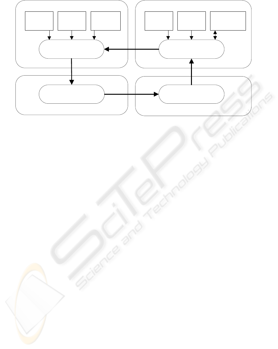
refinement. Figure 1 presents the MultiCAD design
methodology and the modeling levels.
3 RS-MultiCAD ARCHITECTURE
The RS-MultiCAD knowledge-based component
incorporates architectural domain specific
knowledge for constructing buildings. The basic
system architecture is modular giving the possibility
to further extensions. The component is based on
five main modules.
The import/export module is responsible for the
communication with the databases supporting the
input and output of geometric solution, the output of
a new declarative description which comes from
designer modifications, and finally the import and
export of a geometrical model (eg. dxf file format).
The latter enhances the interoperability of the system
since the designer can either import a design from
another CAD system and produce alternative
solutions or export the solution to other CAD system
and continue the design process.
The extraction module applies all domain
specific relation and property types in order to
extract all valid relations and properties of the
objects from a selected solution. The extraction
module is domain independent and facilitates the
extension of knowledge and concept database since
it parses the available knowledge from the database.
Declarative
Modeling
Type of
Relations
Type of
Objects
Solution Generation
Stratified
Modeling
Import/
Export
Model
Rule
Set
Type of
Properties
Object
Set
Description Phase
Generation Phase
Reconstruction Phase
Solution Understanding Phase
Geometric Model
Visualization
Figure 1: MultiCAD design methodology and modeling levels.
ICEIS 2006 - ARTIFICIAL INTELLIGENCE AND DECISION SUPPORT SYSTEMS
84
The control module incorporates all necessary
mechanisms for building, manipulating and updating
the stratified representation. The stratified
representation is dynamic and constructed from the
designer selected solution with a top-down approach
and mainly consists of declarative and geometric
information. Declarative information can be
summarized into object set and rule set. Geometric
information deals with the geometry of each object
that constitutes the scene. The control mechanism is
event-driven and is responsible for the stratified
representation to ensure the correct transition from
one state to another. It handles the designer scene
modifications examining their semantic correctness
and properly updates the stratified representation by
propagating the changes in a mixed way.
The explanation module provides valuable
information about the system reasoning in cases
where a scene modification violates the rule set.
Finally, the RS-MultiCAD component incorporates
a graphical user interface with a 3D editor in order
to visualize the solutions and graphically receive the
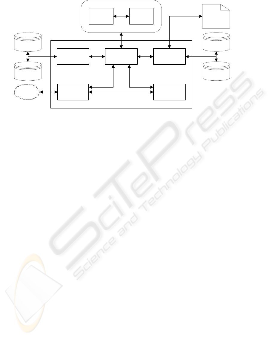
designer requests. Figure 2 illustrates the RS-
MultiCAD system architecture.
3.1 The Stratified Representation
The need of representing geometrical and
declarative information leads to an approach of
using a stratified representation (Sagerer, 1997). A
model in order to become another type of model is
gradually transformed into a sequence of different
levels of abstraction by a sequence of processing
steps.
The stratified representation is an intermediate
level model necessary for connecting the declarative
with the geometric model, and embodies the two
distinct interconnected layers of representation, the
declarative layer which represents the scene
description with the hierarchical decomposition, and
the geometric layer which encapsulates the
geometric aspects of the objects.
The geometric layer of the stratified
representation is based on the bounding box
dimensions of each object which express the object
pure geometric properties, along with any extra
geometric information that can determine the shape
of the object.
RS-MultiCAD inputs a geometric model
produced by the solution generator. That geometric
model contains the geometric information of all
objects and their type as well. The stratified
representation is a dynamic semantic net with nodes
and directed arrows. Every node corresponds to an
object. The arrow label indicates the relations of the
nodes. The labels “parent” and “children” connect
nodes with same level of abstraction and represent
the meronymic relations. The labels “next” and
“previous” connect nodes with the same level of
abstraction and detail. The label “has-geometry”
connects nodes of different layers and represents the
geometry of an object. Finally, the label “has-
topology” connects nodes of the same level of
abstraction indicating the topological relations
among concepts and represents the reflective and
spatial relations.
The construction of the stratified representation is
a top-down process where the hierarchical
decomposition is built based on the geometric
information coming from the geometric model. For
Import/
Export
module
Rule
Set
Object
Set
Designer
GUI/
3D Editor
Control
module
Explanation
module
Extraction
module
Geometric
Model
(dxf, .. etc)
Multimedia
DB
Scene
DB
Concept
DB
Knowledge
DB
RS-MultiCAD
Stratified Representation
Figure 2: RS-MultiCAD system architecture.
A KNOWLEDGE-BASED REVERSE DESIGN SYSTEM FOR DECLARATIVE SCENE MODELING
85
every object, a node is created on the geometric
layer of the stratified representation. As long as all
nodes have been created, the pure geometric
properties lead to the hierarchical decomposition by
creating interconnected nodes on the declarative
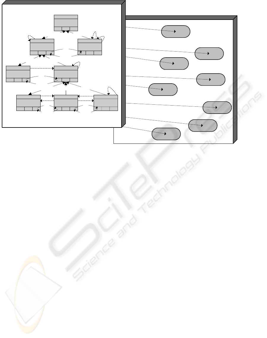
layer of the representation. In Figure 3 appears a
typical stratified representation.
3.2 Scene Manipulation
The dynamic stratified model of RS-MultiCAD
allows the designer to perform geometric and
topological modifications on the scene. As soon as
the designer modifies the scene a special process
starts. Every designer modification must be checked
according to the rule set for its validity and if so the
stratified representation must be properly updated in
order to reflect the real state of the scene. RS-
MultiCAD provides two inference options according
to designer modification which may or may not be
activated. The first refers to check the modification
according to the rule set. A modification is valid as
long as no relation or property of the rule set is
violated otherwise the modification is invalid and is
canceled. If the designer decides not to check the
modifications according to the rule set, the control
module performs a set of mandatory conditions
ensuring the validity of the scene such as, non
overlapping objects of the same level of abstraction,
no object exceeding the overall scene limits, etc. The
second refers to add pure geometric properties to the
rule set that are inferred from the modifications. If
the designer moves an object to a new position, pure
geometric properties relative to move are adding in
the rule set.
The control module properly propagates the
modification by updating the geometric layer of the
representation and activating the extraction module
in order to recalculate all valid relations and
properties. If all relations, properties of the rule set
are not violated the changes are accepted and the
new state of the stratified representation is valid.
Otherwise, the explanation module is activated in
order to record all violated relations, properties of
the rule set and the control mechanism rolls the
representation back to the previous state.
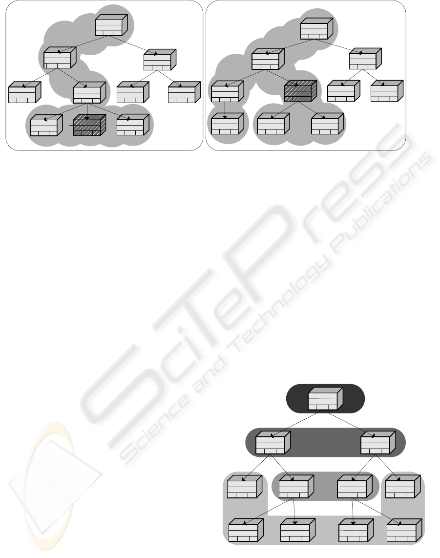
Figure 4 illustrates the propagation policy that
control module follows. On the left-hand side, if a
modification occurs on a leaf node (marked node)
then the propagation starts from its brothers and
continues to ancestors (shaded area). On the right-
hand side, if a modification occurs on an abstract
node (marked node) then the propagation starts from
its children and brothers and continues to ancestors
(shaded area).
The modifications that can occur on the stratified
model refer to abstract or leaf node and can be
divided into two categories according to the
geometrical information that may be supplied by the
designer. In particular, the declarative modifications
are:
Geometric Layer
Geometric
properties
has-geometry
Geometric
properties
has-geometry
Geometric
properties
has-geometry
Geometric
properties
has-geometry
Geometric
properties
has-geometry
Geometric
properties
has-geometry
Geometric
properties
has-geometry
Geometric
properties
has-geometry
Declarative Layer
site
building garage
roof flat
kitchen bedroom bathroom
children/parent parent
children/parent
children/parent
parent
parent parent
previous
next
previous
previous previous
next
next
next
wtl
ltw
ao, el, ew
aw,el,ew
ae,el,ew
lt lt
it=low
it=low
iw=low
Figure 3: The Stratified Representation.
ICEIS 2006 - ARTIFICIAL INTELLIGENCE AND DECISION SUPPORT SYSTEMS
86
• The insertion of an abstract node in the stratified
model can be done by specifying firstly an
already existing node of the model as its parent
and secondly the nodes that become children of
the new abstract node. The result of such a
change will affect the stratified representation
since the object set changes.
• The deletion of an abstract node will eliminate
the sub-tree where the abstract node is root. The
result of such a change will affect the object set
and may affect the rule set as well. The
stratified representation must be updated in
order to reflect the current state of the scene.
• The designer changes the rule set by adding or
deleting a relation or a property of a node.
Moreover, the geometric modifications are:
• Move an object. The designer by providing the
new position moves the object. The stratified
representation must be updated since the move
may affect the position of other objects.
• Scale an object. The designer specifies the scale
factor of the object.
• Resize object. The designer resizes the object by
providing new values for the dimensions of the
object bounding box.
• Insert object. The insertion of a leaf node is
carried out by specifying the geometric
characteristics of the object.
Alter the extra geometric characteristics of an
object. In case where the shape of the object is
complex, the designer can alter the extra geometric
characteristics that define the shape of the object.
3.3 The Resultant Declarative
Description
As soon as the designer has completed all
modifications on the scene, RS-MultiCAD results in
a new declarative description which includes all
modifications required by MultiCAD in order to
generate in the next iteration more promising
solutions by reducing the initial solution space. RS-
MultiCAD provides two optional ways, the manual
and automated. In particular, RS-MultiCAD in the
manual way results in a new rule set that is based on
the initial rule set along with the new relations and
properties that have been changed by the designer.
In this way, RS-MultiCAD offers the designer the
possibility to drive the system to generate a solution
space that is nearer to his requirements.
Figure 5: The propagation policy.
Furthermore, the automated way is based on the
generalization factor (GF). Every hierarchical
GF=1
GF=2
GF=3
GF=4
Figure 4: The propagation policy.
A KNOWLEDGE-BASED REVERSE DESIGN SYSTEM FOR DECLARATIVE SCENE MODELING
87
decomposed tree is divided in distinct levels of
detail. The generalization factor is related to levels
of detail, and its values vary from 1 to maximum
tree depth. The rule set that results from the
automated option, is based on the initial rule set
along with all modifications and also all pure
geometric properties that are implied from the
generalization factor.
Figure 5 schematically shows which pure
geometric properties are included in the rule set
according to generalization factor. If the
generalization factor equals to 1, the pure geometric
properties of the root node are included in the rule
set. If the generalization factor equals to 3, the nodes
that provide their pure geometric properties to the
rule set, are the nodes of the three higher levels of
detail.
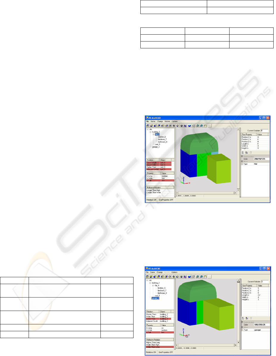
4 RS-MultiCAD
IMPLEMENTATION
RS-MultiCAD has been implemented on Microsoft
Visual Studio .NET platform using C# programming
language and incorporates VectorDraw Viewer
component. The working space of the prototype
presents, on the left-hand side the declarative layer
of the stratified representation, on the right-hand
side the geometric layer and in the middle the
visualized solution. The relations and properties that
belong to the rule set are marked. The current
example shows a site with a building and a garage
inside. The building is further decomposed into a flat
and a roof. The flat consists of a kitchen, bedroom
and bathroom. The stratified representation of the
example is presented in Figure 3.
Tables 1, 2, and 3 present the spatial relations,
reflective relations, and properties that initially
constitute the rule set of the example.
Table 1: Spatial relations.
Garage lower_than Building
Roof adjacent_over, equal_length,
equal_width
Flat
Kitchen adjacent_west, equal_length,
equal_width
Bedroom
Bathroom adjacent_east, equal_length,
equal_width
Bedroom
Bedroom longer_than Kitchen
Bedroom longer_than Bathroom
Table 2: Reflective relations.
Building longer_than_wide
Garage wider_than_long
Table 3: Properties.
Garage is_tall Low
Flat is_tall Low
Bathroom is_wide Low
In case the designer moves the object “flat” to a
new position that causes a possible move of the
children of the “flat”, since it is an abstract node.
The modification is propagating to ancestors
yielding the object “building” with its new position
and also to object “roof” since there is a relation
“adjacent over” in the rule set. Figure 6 illustrates
the result of this move operation.
In case the designer resizes the object “garage”
to a new length and width value, the system
propagates the change to object “building” without
affecting it because there is no relation in the rule set
that connects the two objects. Figure 7 illustrates the
result of the resize operation.
Figure 6: The result of the move operation.
Figure 7: The result of the resize operation.
ICEIS 2006 - ARTIFICIAL INTELLIGENCE AND DECISION SUPPORT SYSTEMS
88
In case the designer inserts a new object, he has
to specify its type and position along with its parent.
The insertion of the new object “roof” causes
modifications on the stratified representation at both
the declarative and the geometric layers. Figure 8
illustrates the result of the insertion. In case the new
object is deleted, figure 7 represents the resulting
state of the scene.
In case the designer modifies the extra geometric
characteristics of the object “roof”, it causes changes
inside the bounding box of the object. The roof
modeling is based on (Makris, 2005). Figure 9
illustrates the changes.
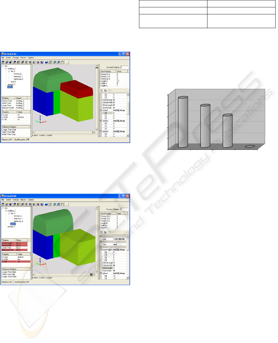
Table 4 shows some experimental results
concerning the manual reduction of the solution
space in the next MultiCAD iteration after the
production of the new declarative description of RS-
MultiCAD. By adding a new relation to the initial
set, the solution space is reduced to solutions that
also satisfy the new designer requirements. Figure
10 shows some experimental results, in logarithmic
scale, concerning the automated production of the
new declarative description.
Table 4: Manual reduction of the solution space.
Rule Set N
o
Solutions
Initial set 32124
initial set + “building
adjacent_west garage”
9270
In each MultiCAD iteration cycle, RS-MultiCAD
constructs a declarative description by adding the
pure geometric properties of the lower level of
detail. MultiCAD in each round generates fewer
solutions and when the generalization factor is set to
maximum depth of the tree, generates one solution
indeed.
Figure 10: Automated reduction of the solution space.
5 CONCLUSIONS
The RS-MultiCAD is a new component of the
MultiCAD architecture, which receives a geometric
model and results into a declarative description. The
MultiCAD declarative conceptual cycle extends to
operate iteratively by the introduction of the
reconstruction phase. During this phase, the internal
representation of RS-MultiCAD, i.e. the dynamic
stratified representation, allows the designer to
manually affect the resultant declarative description.
This is achieved by modifying the scene topology
and the object geometry, in order for MultiCAD, in
the next iteration, to generate geometric solutions
that are closer to designer requirements.
Furthermore, RS-MultiCAD employs two alternative
options, the manual and the automated, which
conduce to the reduction of the solution space by
adding the appropriate pure geometric properties of
the objects to the resultant declarative description
thus also reducing the solution generation time.
RS-MultiCAD can be compared with
XMultiFormes (Sellinger, 1998). The XMultiFormes
project approaches the subject by a low-level
process and gives special attention on man machine
interaction. On the other hand, RS-MultiCAD uses a
high-level knowledge-based approach and supports
Figure 8: The result of insertion.
Figure 9: The result of changing extra geometric
characteristics.
32124
6120
760
1
1
10
100
1000
10000
100000
No Solutions
1234
Generalization Factor
A KNOWLEDGE-BASED REVERSE DESIGN SYSTEM FOR DECLARATIVE SCENE MODELING
89

the iterative process of the declarative modeling by
an automatic way. The reduction of the solution
space proves the quality of the resultant declarative
model in every cycle of the iterative process.
ACKNOWLEDGMENTS
This study was co-funded by 75% from the
European Union and 25% from the Greek
Government under the framework of the Education
and Initial Vocational Training Program –
‘Archimedes’.
REFERENCES
Bardis G., Miaoulis G., Plemenos D., 2005. Intelligent
solution evaluation based on alternative user profiles.
ICES’05. ICEIS Press.
Golfinopoulos V., Dragonas J., Miaoulis G., Plemenos D.,
2004. Declarative design in collaborative environment,
3IA’2004, Limoges, France.
Golfinopoulos V., Miaoulis G., Plemenos D., 2005. A
semantic approach for understanding and manipulating
scenes, 3IA’2005, Limoges, France.
Fisher B. Robert 2004, “Applying knowledge to reverse
engineering problems”, Computer Aided Design 36,
pp. 501-510.
Lucas M., Martin D., Martin P., Plemenos D., 1989. Le
projet ExploFormes : quelques pas vers la
modélisation de formes, BIRGE, no 67, pp 35-49.
Makris D., Ravani I., Miaoulis G., Skourlas C., Fribault
P., Plemenos D., 2003. Towards a domain-specific
knowledge intelligent information system for CAAD,
3IA’2003, Limoges, France.
Makris D., 2005, Etude et réalisation d'un système
déclaratif de modélisation et de génération de styles
par algorithmes génétiques, PhD Thesis, University of
Limoges, France.
Miaoulis G., 2002. Contribution à l'étude des systèmes
d'information multimédia et intelligents dédiés à la
conception déclarative assistée par l'ordinateur – Le
projet MultiCAD (in French), PhD Thesis, University
of Limoges, France.
Miaoulis G., Plemenos D., Skourlas C., 2000. MultiCAD
Database: Toward a unified data and knowledge
representation for database scene modeling, 4
e
3IA’2000, Limoges, France.
Miaoulis G., Plemenos D., 1998. Basic elements of a
design process and information system paradigm
associated to the declarative modelling systems, Poster
in 3IA’1998, Limoges, France.
Miaoulis G., Plemenos D., 1996. Propositions pour un
système d’information multimédia intelligent dédié à
la CAO – Le projet MultiCAD (in French). Report of
research MSI 96-03, Limoges, France.
Peng Q., Loftus M., 2001. Using image processing based
on neural networks in reverse engineering.
International Journal of Machine Tools &
Manufacture 41, pp 625–640.
Plemenos D., 1991. A contribution to study and
development of scene modeling, generation and
display techniques – the MultiFormes project,
Professorial dissertation, University of Nantes, France.
Plemenos D., 1995. Declarative modeling by hierarchical
decomposition. The actual state of the MultiFormes
project, GraphiCon'95, St Petersburg, Russia.
Plemenos D., Miaoulis G., Vassilas N., 2002. Machine
learning for a general purpose declarative scene
modeler. International Conference GraphiCon'2002,
Nizhny Novgorod, Russia.
Plemenos D., Tamine K., 1997. Increasing the efficiency
of declarative modeling. Constraint evaluation for the
hierarchical decomposition approach. International
Conference WSCG’97, Plzen, Czech Republic.
Ravani I., Makris D., Miaoulis G., Constantinides P.,
Petridis A., Plemenos D., 2003. Implementation of
architecture-oriented knowledge framework in
MultiCAD declarative scene modeling system, 1
st
Balcan Conference in Informatics, Greece.
Ravani J., Makris D., Miaoulis G., Plemenos D., 2004.
Concept-Based declarative description subsystem for
Computer Aided Declarative Design (CADD). 7
e
3IA’2004, Limoges, France.
Sagerer G., Niemann H., 1997. Semantic networks for
understanding scenes, Plenum Press, N. York.
Sellinger D., 1998. Le modélisation géométrique
déclarative interactive. Le couplage d’un modeleur
déclaratif et d’un modeleur classique. PhD Thesis,
University of Limoges, France.
Vassilas N., Miaoulis G., Chronopoulos D., Konstantinidis
E., Ravani I., Makris D., Plemenos D, 2003.
MultiCAD-GA: A System for the design of 3D forms
based on genetic algorithms and human evaluation.
SETN02 Conference, LNAI 2308, Springer-Verlag,
pp. 203-214.
Vergeest J.S.M., Langerak R., Song Y., Wang C.,
Brosvoort W.F., Nyirenda R.J., 2005. Towards reverse
design of freeform shape. WSCG 2005, Plzen, Czech
Republic.
Wang C.L. Charlie, Chang K.K. Terry, Yuen M.F.
Matthew, 2003. From laser-scanned data to feature
human model: a system based on fuzzy logic concept.
Computer-Aided Design 35;3, pp. 241-253.
ICEIS 2006 - ARTIFICIAL INTELLIGENCE AND DECISION SUPPORT SYSTEMS
90
