
UBIQUITOUS KNOWLEDGE MODELING
FOR DIALOGUE SYSTEMS
Porfírio Filipe
1,2
, Nuno Mamede
1,3
1
L
2
F INESC-ID - Spoken Languages Systems Laboratory, Lisbon, Portugal
2
ISEL – Instituto Superior de Engenharia de Lisboa, Lisbon, Portugal
3
IST – Instituto Superior Técnico, Lisbon, Portugal
Keywords: Spoken Dialogue System, Domain Model.
Abstract: The main general problem that we want to address is the reconfiguration of dialogue systems to work with a
generic plug-and-play device. This paper describes our research in designing knowledge-based everyday
devices that can be dynamically adapted to spoken dialogue systems. We propose a model for ubiquitous
knowledge representation that enables the spoken dialogue system to be aware of the devices belonging to
the domain and of the tasks they provide. We consider that each device can be augmented with
computational capabilities in order to support its own knowledge model. A knowledge-
-based broker adapts the spoken dialogue system to deal with an arbitrary set of devices. The knowledge
integration process between the knowledge models of the devices and the knowledge model of the broker is
depicted. This process was tested in the home environment domain.
1 INTRODUCTION
*
A Spoken Dialogue System (SDS) should be a
computational entity that allows access to any device
by anyone, anywhere, at anytime, through any
media, allowing its user to focus on the task, not on
the tool. Only in the last decade, with major
advances in speech technology, have large-scale
working systems been developed and, in some cases,
introduced into commercial environments (McTear,
2002). Nevertheless, many implementations of
dialogue managers perform input interpretation,
output generation, and domain dependent tasks. This
approach may easily lead to situations in which the
Dialogue Manager (DM) is a monolithic component.
Monolithic components make it harder to build
modular, distributed systems, and reusable
components (O’Neill and McTear, 2000). Typically,
these issues are addressed through architectures that
integrate reusable components. Some progresses can
be seen in (Bohus and Rudnicky, 2003), (O’Neill et
al., 2003), (Pakucs, 2003), (Polifroni and Chung
*
This research has been partially supported by Fundação para a
Ciência e Tecnologia under project number
POSI/PLP/41319/2001 (POSI and FEDER)
2002), (Neto et al., 2003) and (Turunen and
Hakulinen, 2003). The main problem we want to
address is the reconfiguration of SDSs to deal with
heterogeneous plug-and-play devices, which can be
seen as a problem of portability across domains.
Fig. 1 shows an architecture schema where X
n
is
a generic device and A, B, C, and D are the other
components of the SDS. Within a ubiquitous
domain, we do not know, at design time, all the
devices that will be available and which tasks they
provide. In order to address this problem we
describe a model for ubiquitous knowledge
representation, which was introduced in (Filipe and
Mamede, 2004). We propose a knowledge model
that is shared by each device and by a broker. We
assume that the devices have computational (and
communication) capabilities to support their own
Fi
g
ure 1: Ada
p
tation of the SDS to the Domain.
143
Filipe P. and Mamede N. (2006).
UBIQUITOUS KNOWLEDGE MODELING FOR DIALOGUE SYSTEMS.
In Proceedings of the Eighth International Conference on Enterprise Information Systems - HCI, pages 143-150
DOI: 10.5220/0002498301430150
Copyright
c
SciTePress

knowledge model. The broker, which is the SDS
component that manages the Domain Knowledge,
dynamically adapts the SDS to deal with an arbitrary
set of devices. The basic strategy to work within a
ubiquitous domain is the automatic integration of
Domain Knowledge from Global Knowledge built-
in in the broker and Local Knowledge built-in in
each device. The Knowledge Integration Process is
bilateral: the SDS must be prepared to deal with an
arbitrary set of devices (defining Global Knowledge)
and each device must be prepared to be operated by
the SDS (defining Local Knowledge).
2 KNOWLEDGE MODEL
The Knowledge Model is composed by three main
components: a Discourse Model, a Task Model, and
a World Model.
These components encapsulate the descriptors of the
entities that can be mentioned by the user. A general
class diagram of the Knowledge Model is presented
in Fig. 2.
2.1 Discourse Model
The Discourse Model defines a conceptual support,
grouping a set of concept definitions used to
describe classes, devices and the tasks they provide.
2.1.1 Concept Definition
A Concept is an atomic knowledge unit that has a
unique identifier (ID). Each concept have a
Linguistic Descriptor that it describes, in linguistic
terms. This descriptor groups Multi Word Unit
(MWU) composed by single words (Word).
The concepts have some MWU to define the
associated vocabulary: synonyms, acronyms and
even antonyms. Fig. 3 shows the relations between
these classes. The vocabulary is organized by
language, allowing a multi-lingual definition of the
concepts. A concept can also have a Semantic
Descriptor that has references to other knowledge
representations, for instance, an ontology (Gruber,
1992) or a lexical database such as WordNet
(WordNet, 2005).
The Discourse Model organizes the concepts by
classes and subclasses as shown in Fig. 4. The most
relevant classes are Device and Task. The other
classes are used to represent task roles.
2.1.2 Device and Task Representation
A concept, representing a Task name, can be an
instance of two subclasses: Action, when the task
can modify the device state; or Acquisition, when it
never modifies the device state. A Device name is a
concept of the class Name and a Device class can be
an instance of two subclasses: Active, when
providing at least one action task; or Passive, when
providing only acquisition tasks. For instance, an
oven is an active device and a thermometer is a
passive device. These device and task classifications
are important to prevent task execution conflicts.
2.1.3 Representation of Task Roles
The representation of task roles involves two
different aspects: role default Value and role
Category used to establish the role range. The
default value can be an instance of two subclasses:
Quantity, to represent default numbers, for instance,
zero; or Attribute, to represent default attributes, for
instance, the black color. The role category can be
an instance of two subclasses: Collection, when a
role has a limited set of attributes, for instance, the
rainbow colors; or Unit, when a role represents a
physical dimension, for instance, the distance in
meters, miles or inches.
Figure 3: Concept Definition.
Fi
g
ure 4: Knowled
g
e Model Main Com
p
onents.
Fi
g
ure 2: Conce
p
t Classes.
ICEIS 2006 - HUMAN-COMPUTER INTERACTION
144

2.2 Task Model
The Task Model represents the set of available tasks
provided by existing device(s). Typically, before
performing a task, it is necessary to express the
argument values or parameters that establish the
execution conditions. It is mandatory for these
values to be represented in the Discourse Model.
The Task Model is also used to check the state of the
world before and after a task execution.
2.2.1 State of the World
The state of the world is represented by the set of
individual states of each device. The state of each
device is obtained by calling the provided
acquisition tasks. For instance, when the task is
“switch on the light”, we have to check if the “light”
is not already “switched on” and after the task
execution, we have to check if the “light” has really
been “switched on”.
2.2.2 Task Descriptor
A Task Descriptor is used to represent a task in the
Task Model. Fig. 5 shows the class diagram.
A Task Descriptor is composed by a unique
identifier (IDT), a name (Acquisition, Action), two
optional lists (In List, Out List) of roles that describe
in and out task parameters and two optional rules
(Rule) applicable to the state of the world.
The Initial rule is checked before the task call
and must produce the logical value true before the
task execution. The Final rule is checked after the
task execution and must produce the logical value
true when a successful task execution occurs. A rule
is expressed using relational operators (‘<’, ‘>’, ‘=’,
‘<>’, ‘<=’, ‘>=’) and logical operators (‘Or’, ‘And’).
When we need to specify a task argument value in a
rule expression, the ID, of the concept that is the role
Name, must be between square parenthesis (‘[‘,’]’).
When we need to specify a simple concept, its ID
must be between braces (‘{‘,’}’). For instance, we
can write the rule “{1} > [2]” to denote that. Each
task argument is represented in its Task Descriptor
by a Role that is associated with other classes (see
Fig. 6). A role describes the possible values that can
be used to instantiate a task argument. An In Role
describes the values that can be used as input
parameters. An Out Role describes the values that
can be used as output parameters. All roles have a
name (Attribute) and a range (Category). Each role
has an optional Restriction rule to check the
parameters, for instance, the parameter must be
positive. An In Role may have an optional default
value (Quantity, Attribute). When the default value
is not present, the task argument is mandatory. The
task roles are organized in two role lists (In Role and
Out Role) that have a Validation rule to check their
parameters. The validation rule of an In Role list is
evaluated before the task execution. The validation
rule of an Out Role list is evaluated after the task
execution.
2.3 World Model
The World Model represents the devices that are part
of the world. This model integrates two components:
a Type Hierarchy and a Mediator (see Fig. 7).
2.3.1 Type Hierarchy
The Type Hierarchy is an aggregation of device
class descriptors (Class Descriptor). Each device
class descriptor has a unique identifier (IDCL) and a
concept device class name. This descriptor is
associated with a set of identical devices and
maintains a list of its super classes. For instance, a
device class may be either an appliance, or a
thermometer, or a window, or a table.
Figure 7: Model Components and Descriptors.
Fi
g
ure 5: Task Re
p
resentation.
Fi
g
ure 6: Re
p
resentation of a Task Role.
UBIQUITOUS KNOWLEDGE MODELING FOR DIALOGUE SYSTEMS
145

2.3.2 Mediator
The Mediator is an aggregation of device descriptors
(Device Descriptor) that are instances of device
classes representing a physical device that provides
tasks. Each device descriptor has a unique identifier
(IDA) and a concept device name.
2.4 Knowledge Representation
The knowledge representation is essentially based
on the descriptors (Task Descriptor, Device
Descriptor, Class Descriptor) that are coupled using
bridges (Bridge). After the definition of the needed
concepts belonging to the Discourse Model, we can
fill the descriptors without following a predefined
sequence. Finally, we can introduce the instances of
the bridge class that associate task descriptors to
device descriptors (Bridge T) and device descriptors
to class descriptors (Bridge C).
Fig. 8 shows the knowledge model descriptors
and bridges directly involved in the knowledge
representation. A device knowledge model has only
one device descriptor that describes the device itself
and must have at least one task descriptor. The
broker knowledge model does not include any
device descriptors, because the device descriptors
are added only at runtime.
3 KNOWLEDGE INTEGRATION
PROCESS
The goal of the Knowledge Integration Process
(KIP) is to automatically update the Domain
Knowledge (DK), integrating the Global Knowledge
(GK) included in the broker and the Local
Knowledge (LK) included in the domain devices.
The integration process is composed by two other
processes: (i) the device attachment process and (ii)
the device detachment process.
3.1 Similar Concepts
Two similar concepts cannot exist in the same
Discourse Model. In this context, we assume that
two concepts are similar when: their identifiers are
equal, one of theirs semantic descriptors is equal or
theirs linguistic descriptors are equal. In special
cases, two concepts may be considered as similar by
other convenient similarity criteria. At its starting
point, the KIP puts side by side the concept
definitions in DK and the concept definitions in LK,
which are going to be merged. The KIP uses a
Conversion Concept Table (CCT), linked to each
broker’s Device Descriptor, to convert identifiers of
similar concepts.
3.2 Device Attachment Process
When a device is attached (activated), it searches for
the broker component of the SDS. After establishing
the initial communication, the broker leads the
device attachment process following the next nine
steps, in order to update its Knowledge Model:
I. A new Device Descriptor is added to the
broker’s Mediator;
II. An empty CCT is linked to the new Device
Descriptor;
III. The concepts of the device Discourse Model
fill the first column of the CCT;
IV. Each concept in the first column of the CCT,
with a similar concept in the broker’s
Discourse Model, is associated with its similar,
filling the second column of the CCT;
V. The other concepts in the first column of the
CCT (without a similar concept in the broker’s
Discourse Model) are added to the broker’s
Discourse Model;
VI. Each new device Task Descriptor is added to
the broker’s Task Model and its concepts
identifiers are replaced by the existing similar
concepts identifiers, using the CCT;
VII. Each Class Descriptor in the device’s Type
Hierarchy is integrated in the broker’s Type
Hierarchy and its concepts identifiers are
replaced by the existing similar concepts
identifiers, using the CCT;
VIII. The new Device Descriptor is associated
with its class descriptor using the appropriate
bridge (Bridge C);
IX. The new Device Descriptor is associated
with its Tasks Descriptors using the
appropriate bridge (Bridge T).
Fi
g
ure 8: Model Descri
p
tors and Brid
g
es.
ICEIS 2006 - HUMAN-COMPUTER INTERACTION
146

3.3 Device Detachment Process
When the broker detects that a device has been
detached (deactivated), it follows the next five steps,
in order to update its Knowledge Model:
I. The Task Descriptors exclusively associated
with the detached Device Descriptor are
removed from the broker’s Task Model;
II. The Class Descriptors exclusively associated
(in a bridge or in a CCT) with the device
descriptor are removed from the broker’s Type
Hierarchy;
III. Concepts that appear only in the CCT are
removed from the broker’s Discourse Model;
IV. The Bridges associated to the Device
Descriptor of the detached device are removed
from the broker’s Knowledge Model;
V. The Device Descriptor of the detached device
is removed from the broker’s Mediator.
4 EXAMPLE
This section describes a complete example of local
knowledge modeling. For this, we show how to
define the content of the local knowledge model
components (discourse model, task model and world
model). The presented example is intentionally
simple; however, it also illustrates the modeling of
global knowledge because the model components
are the same ones.
This example assumes that we want to control,
through a SDS, a “kitchen window” with an
electrochromatic glass that can change the visual
aspect of the glass to: opaque, transparent, blue,
green or red.
Fig. 9 shows the visual aspect of the glass for
transparent and opaque.
IDT Task Name Role
1 “OPENING” -
2 “CLOSING” -
3 “PAINTING” “COLOR”
4 “ASKING” &”COLOR”
5 “ASKING” &”STATE”
Table 1 shows the task identifiers, the task names
and the role names of the available tasks. Now we
must fill the Knowledge Model of the “kitchen
window” (defining LK) that should contain only the
needed knowledge to allow its subsequent
integration in the DK.
4.1 Discourse Model
The task “OPENING” and “CLOSING” do not have
roles. The task “PAINTING”, that changes the
window color, has one input role “COLOR” to
receive all the possible colors of the window. The
task “ASKING” has two distinct forms with one
output role, that allows asking about the current
“COLOR” {“BLUE”, “GREEN”, “OPAQUE”,
“RED”, “TRANSPARENT”} of the window and
about the current “STATE” {“OPENED”,
“CLOSED”}. Table 2 shows the concept identifiers,
the classes and the Multi Word Units needed for
defining concepts in the Discourse Model.
ID Class MWU
S
1
Acquisition asking
O
1
Action closing
O
2
Action opening
O
3
Action painting, changing
I
1
Active artifact
I
2
Active window
B
1
Attribute blue, sapphire
B
2
Attribute closed
B
3
Attribute green, emerald
B
4
Attribute ink
B
5
Attribute opaque, not clear
B
6
Attribute opened
B
7
Attribute red, ruby
B
8
Attribute transparent, clear
L
1
Collection color
L
2
Collection state
N
1
Name kitchen window
The concepts described in Table 2 are used to
define: (i) the tasks (in the Task Model); (ii) the
device classes (in the Type Hierarchy); and (iii) the
device name (in the Mediator).
ID Collection ID Attribute
L
1
B
1
L
1
B
3
L
1
B
5
L
1
B
7
L
1
B
8
L
2
B
2
L
2
B
6
Table 3: Collection Definitions.
Table 2: Conce
p
t Definitions.
Table 1: Kitchen Window Task Set.
Fi
g
ure 9: Illustration of the Kitchen Window.
UBIQUITOUS KNOWLEDGE MODELING FOR DIALOGUE SYSTEMS
147

Table 3 presents the collections that are used for
establishing the ranges of the task roles. Table 4
shows examples of semantic descriptors obtained
from the lexical database WordNet. Columns Label
and Sense (Table 4) are used to identify similar
concepts and the Description column is used for
documentation (it is never used to evaluate the
similarity between concepts). Column ID is the
concept identifier.
ID Description Label Sense
B
1
color intermediate between
green and violet
adjective 1
B
2
not open
adjective 3
B
3
color between blue and yellow
in the color spectrum
adjective 1
B
5
not clear; not transmitting or
reflecting light or radiant energy
adjective 1
B
6
made open or clear
adjective 2
B
7
color at the end of the color
spectrum (next to orange)
adjective 1
B
8
transmitting light; able to be
seen through with clarity
adjective 1
O
1
cause to close or to become
close
verb 8
O
2
cause to open or to become open
verb 1
S
1
inquire about
verb 1
4.2 Task Model
After the characterization of the Discourse Model
we should describe the Task Model indicating tasks
(see Table 5), task roles (see Table 6) and tasks rules
(see Table 7). In Table 7, “&X” is a dummy variable
used to receive the returned value from the called
task.
IDT ID Name
1 O
2
2 O
1
3 O
3
4 S
1
5 S
1
IDT ID Name ID Range ID Default Role Type
3 B
4
L
1
B
5
In
4 L
1
L
1
- Out
5 L
2
L
2
- Out
IDT Initial Final
1 {S
1
}(&X); &X={B
2
} {S
1
}(&X); &X={B
6
}
2 {S
1
}(&X); &X={B
6
} {S
1
}(&X); &X={B
2
}
3 {S
1
}(&X); &X<>[B
4
] {S
1
}(&X); &X=[B
4
]
4.3 World Model
The World Model contains the Type Hierarchy and
the Mediator. Table 8 shows the Type Hierarchy
description where the class I
2
(window) is linked, via
IDSCL column, to the super class I
1
(artefact).
IDCL ID IDSCL
1 I
1
-
2 I
2
1
In more complex cases, Table 8 may have
several class definitions. Table 9 shows the
definition of the name of the unique device that is
the “kitchen window”.
IDA ID
1 N
1
4.4 Bridges
Finally, we should link the descriptors using
Bridges. First, we should link the device (see Table
9) to its class (see Table 8) as is presented in Table
10. Next, we should link the device to its tasks (see
Table 5) as is presented in Table 11.
IDA IDCL
1 1
IDA IDT
1 1
1 2
1 3
1 4
1 5
4.5 Task Invocation
The invocation of a task, made by the DM trough the
broker (see Figure 1), uses a generic device proxy
for sending and receiving the parameters list. The
identifiers of the concepts in the parameters list are
converted before and after the task invocation using
the CCT. For instance, if the DM requests to paint
the “kitchen window” using the “RED” color, the
broker will send to the device the concept identifiers
O
3
and B
7
obtained using the CCT. Before the task
invocation, the DM must check the Initial Rule
“{S
1
}(&X); &X<>{B
7
}”, and, after the task
Table 11: Brid
g
es Device to Tas
k
.
Table 10: Brid
g
e Device to Class.
Table 9: Device Definitions.
Table 8: Class Definitions.
Table 7: Task Rule Definitions.
Table 6: Task Role Definitions.
Table 5: Task Definitions.
Table 4: Semantic Descri
p
tors.
ICEIS 2006 - HUMAN-COMPUTER INTERACTION
148

execution, the DM must also check the Final Rule
“{S
1
}(&X); &X={B
7
}”.
5 TESTING KIP
KIP was tested in a home environment domain with
common devices and household appliances that are:
Air Conditioner (63 - concepts), Freezer (96 -
concepts), Fryer (92 - concepts), Light Source (62 -
concepts), Microwave Oven (167 - concepts), Table
(48 - concepts), Water Faucet (63 - concepts),
Window (44 - concepts) and a Window Blind (65 -
concepts). All the devices are using 700 concepts.
Initially the GK (that is equal to DK) is using 261
concepts. After the attachment of all devices the DK
retain 360 concepts. The knowledge integration rate
is 360/700*100 = 51%. Each Knowledge Model for
devices and broker is supported by a relational
database with 19 (nineteen) tables.
Fig. 10 show a screenshot of the home
environment domain simulator, developed originally
for Portuguese users. On the bottom of the screen we
can see an electrochromatic Table device simulator.
This simulator allows the debug of KIP and the
simulation of the interaction made by the Dialogue
Manager. We can attach and detach devices, do
requests of tasks, obtain the answers and observe the
devices behaviour. We can also consult and print
several data about the several Knowledge Models
and about the task execution progress. Fig. 11 shows
the screen of the Fryer simulator after the execution
of the request: “frying chinese spring rolls”. This
screen shows the automatically select temperature
(180 ºC) and duration (7 minutes) of the frying
process. Fig. 12 shows the screen of the Microwave
Oven simulator after the execution of the request:
“defrosting carrots”. This picture shows the
automatically select power (300 watts – see symbol)
and duration (8 minutes) of the defrosting process.
Fig. 13 shows the screen of the Freezer simulator
after the execution of the request: “asking the
amount of carrots”. The table in the picture shows
the selected type of food. However, the domain
simulator also returns the answer “1 package with
300 g” in a text window. We can also execute
requests that evolve relational operators, for
instance: “asking the type of food with amount less
than five”.
Fi
g
ure 13: Freeze
r
Simulator.
Fi
g
ure 12: Microwave Oven Simulator.
Figure 11: Deep Fryer Simulator.
Fi
g
ure 10: Screenshot of the Domain Simulato
r
.
UBIQUITOUS KNOWLEDGE MODELING FOR DIALOGUE SYSTEMS
149
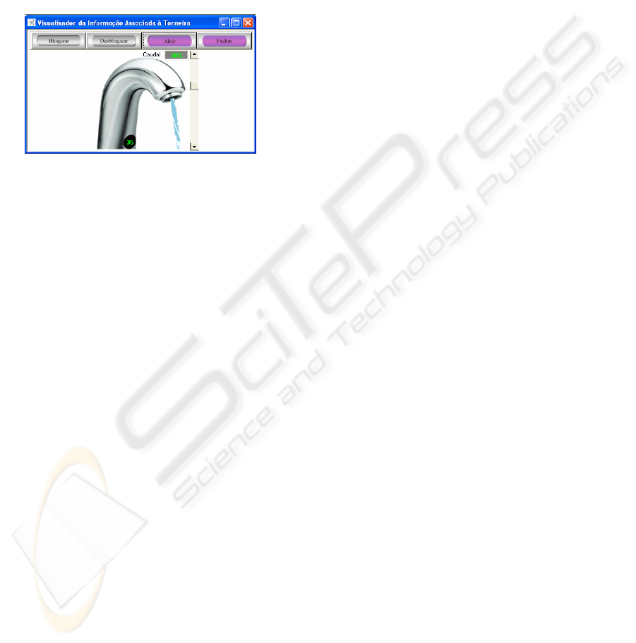
The concept “CARROT” is shared by the
Microwave Oven and by the Freezer. We have only
one definition of the concept “CARROT” in the
broker’s Knowledge Model. Fig. 14 shows the
screen of the Water Faucet simulator after the
execution of the request “opening the faucet”. The
debit of water (30%) and temperature (35 ºC) are
automatically modified, when we increase or
decrease the water debit, or increase or decrease the
water temperature.
6 DISCUSSION
In the near future, intelligent devices embedded in
everyday artefacts will surround people. This means
integration of microprocessors into devices such as
household appliances, furniture or even clothing.
Achieving interoperability using plug-and-play
devices, demands an explicit agreement on meaning,
for instance, using controlled vocabularies. In this
perspective, it seems that in simple cases, agreement
on meaning can be achieved, facilitating the
interoperability and the definition of standards.
However, the general and special needs of
computational systems, such as a SDS, cannot be
satisfied with universal specifications that have to be
limited due to practical reasons, presenting
deficiencies in aspects normally considered
essentials. On the other hand, for instance, we could
use the FIPA device ontology (FIPA DOS, 2002) to
represent memory type, connection, hardware
description, software description and so on.
Nevertheless, generally, this kind of information is
not relevant for SDSs because users are not
particularly interested in asking about that kind of
information.
7 CONCLUSION
The work reported in this paper is a significant
contribution to improve the flexibility, and
simultaneously the robustness, of the SDS being
developed in our lab. Our proposal is about an
important issue around plug-and-play architectures:
agreement on meaning. We have described a
Knowledge Model and a Knowledge Integration
Process. This process deals dynamically with
communication interoperability between the SDS
and a set of heterogeneous devices. The ideas
presented in this paper have been applied, with
success, in complex devices such as household
appliances.
REFERENCES
Bohus, D. and Rudnicky, A., 2003. RavenClaw: Dialog
Management Using Hierarchical Task Decomposition
and an Expectation Agenda. In Eurospeech 2003,
Geneva, Switzerland.
Filipe, P. and Mamede, N., 2004. Towards Ubiquitous
Task Management. In Interspeech 2004, Jeju Island,
Korea.
FIPA DOS, 2002. FIPA Device Ontology Specification
(http://www.fipa.org/specs/fipa00091/).
Gruber, T., 1992. Toward Principles for the Design of
Ontologies Used for Knowledge Sharing. In
International Workshop on Formal Ontology, Padova,
Italy Padova, Italy.
McTear, M., 2002. Spoken Dialogue Technology:
Enabling the Conversational Interface. In ACM
Computing Surveys, Volume 34.
Neto, J., Mamede, N., Cassaca, R. and Oliveira, L., 2003.
The Development of a Multi-purpose Spoken
Dialogue System. In Eurospeech 2003, Geneva,
Switzerland.
O’Neill, I. and McTear, M., 2000. Object-Oriented
Modelling of Spoken Language Dialogue Systems. In
Natural Language Engineering 6, Cambridge
University Press, Cambridge, UK.
O’Neill, I., Hanna, P., Liu, X. and McTear, M., 2003. An
Object-Oriented Dialogue Manager. In Eurospeech
2003, Geneva, Switzerland.
Pakucs, B., 2003. Towards Dynamic Multi-Domain
Dialogue Processing. In Eurospeech 2003, Geneva,
Switzerland.
Polifroni, J. and Chung, G., 2002. Promoting Portability in
Dialogue Management. In ICSLP 2002, Denver,
Colorado, USA.
Turunen, M. and Hakulinen, J., 2003. JASPIS
2
– An
Architecture for Supporting Distributed Spoken
Dialogues. In Eurospeech 2003, Geneva, Switzerland.
WordNet. 2005. WordNet a Lexical Database for the
English Language (http://wordnet.princeton.edu/).
Fi
g
ure 14: Water Faucet Simulator.
ICEIS 2006 - HUMAN-COMPUTER INTERACTION
150
