
On-demand Loading of Pervasive-oriented Applications
Using Mass-market Camera Phones
⋆
Marco Avvenuti and Alessio Vecchio
Dipartimento di Ingegneria della Informazione
Universit
`
a di Pisa
56122 Pisa, Italy
Abstract. Camera phones are the first realistic platform for the development of
pervasive computing applications: they are personal, ubiquitous, and the built-
in camera can be used as a context-sensing equipment. Unfortunately, currently
available systems for pervasive computing, emerged from both academic and in-
dustrial research, can be adopted only on a small fraction of the devices already
deployed or in production in the next future. In this paper we present an exten-
sible programming infrastructure that turns mass-market phones into a platform
for pervasive computing.
1 Mobile phone: A Platform for Pervasive Computing
Pervasive computing tries to make M. Weiser’s vision [1] a reality by saturating the
environment with computing and communication devices: the most of the infrastructure
is often invisible and supports user’s activities with an interaction model that is strongly
human-centric. Today, almost fifteen years later, despite significant progresses in both
hardware and software technologies, this vision is still not completely realizable or
economically convenient.
Supporting the interaction between users and the environment can be greatly sim-
plified if we relax the interaction model and include a personal device as the access
medium. Mobile phones are the most obvious candidates: they are in constant reach
of their users, have wireless connectivity capabilities, and are provided with increasing
computing power [2]. Even better results can be achieved with those phones that are
equipped with a camera. Instead of manually getting information or editing configu-
rations, users can point physical objects to express their will of using them: taking a
picture of the objects would suffice to setup the link with the offered services.
Relaying on an image acquisition device does not impose a strict limit to the share
of possible users, since an always growing number of commercially available mobile
phone is equipped with an integrated camera: according to recent studies [3], over 175
million camera phones were shipped in 2004 and, by the end of the decade, the global
population of camera phones is expected to surpass 1 billion.
⋆
This work is partially supported by the Italian Ministry for Education and Scientific Research
(MIUR) in the framework of the FIRB-VICOM project.
Avvenuti M. and Vecchio A. (2006).
On-demand Loading of Pervasive-oriented Applications Using Mass-market Camera Phones.
In Proceedings of the 3rd International Workshop on Ubiquitous Computing, pages 39-48
DOI: 10.5220/0002501600390048
Copyright
c
SciTePress
However, the acquisition of context-related information through images is not a triv-
ial task, especially with resource-constrained devices. To ease the recognition process,
objects can be labeled with visual tags readable by machines. Once decoded, visual
tags either directly provide information about the resource they are attached to or, if the
amount of information is too large, they act as resource identifiers that can be used to
gather information from the network.
In this paper, we describe the design and the implementation of POLPO
1
(Polpo is
On-demand Loading of Pervasive-Oriented applications), a software system that turns
mass-market phones into a platform for the development of pervasive applications. With
POLPO, a phone with a built-in camera and compatible with the Java 2 Micro Edition
(J2ME) platform is able to get context information by decoding visual tags attached to
real-world objects. POLPO supports dynamic loading and installation of custom appli-
cations used to interact with the desired resources.
2 Background and Contribution
In this section we summarize the most relevant solutions based on visual tags and the
contribution of our system in this field.
Cybercode [4] is a visual tagging system based on a two-dimensional barcode tech-
nology. The system has been used to develop several augmented reality applications
where the physical world is linked to the digital space trough the use of visual tags.
Cybercode is one of the first systems where visual tags can be recognized by low-cost
CCD or CMOS cameras, without the need for separate and dedicated readers. Each Cy-
bercode symbol is able to encode 24 or 48 bits of information. The system has been
tested with notebook PCs and PDAs.
In [5] the author presents a system that turns camera-phones into mobile sensors for
two-dimensional visual tags. By recognizing a visual tag, the device can determine the
coded value, as well as additional parameters, such as the viewing angle of the camera.
The system includes a movement detection scheme which enables to use the mobile
phone as a mouse (this is achieved by associating a coordinate scheme to visual tags).
The communication capability of the mobile phone is used to retrieve information re-
lated to the selected tag and to interact with the corresponding resource. Tag recognition
and motion detection algorithms were implemented in C++ for Symbian OS.
The Mobile Service Toolkit (MST) [6] is a client-server framework for developing
site-specific services that interact with users’ smart phones. Services are advertised by
means of machine-readable visual tags, which encode the Bluetooth device address of
the machine that hosts the service (Internet protocols addressing could be supported as
well). Visual tags also include 15 bits of application-specific data. Once the connec-
tion has been established, MST servers can request personal information to the client
to provide personalized services. Site-specific services can push user interfaces, ex-
pressed with a markup language similar to WML (Wireless Markup Language), to smart
phones. MST also provide thin-client functionality: servers can push arbitrary graphics
1
The Italian name for the octopus vulgaris, a cephalopod of the order octopoda, probably the
most intelligent of the invertebrates.
40

to the phone’s display which in turn forwards all keypress events to the server. The
client-side is written in C++ and requires Symbian OS.
A similar approach is described in [7], where the authors propose an architecture for
a platform that supports ubiquitous services. Real-world objects are linked to services
on the network through visual tags based on geometric invariants that do not depend
on the viewing direction [8]. But differently from other solutions, image processing
does not take place on the user’s device: pictures are sent to a server where they are
elaborated and converted into IDs.
Instead of using two-dimensional barcodes, an alternative way of performing object
recognition is the one based on radio frequency identification (RFID): small tags, at-
tached to or incorporated into objects, that respond to queries from a reader. However
this solution, that can be useful in many pervasive computing scenarios, is not particu-
larly suitable when the interaction is mediated by mobile phones, that lack the capability
of reading RFIDs.
In our opinion, currently available solutions present two major drawbacks: i) they
are limited to specific hw/sw platforms (i.e. Symbian OS), excluding most of the models
of mobile phones already shipped and in production in the near future; ii) the software
needed to interact with the environment is statically installed onto the mobile phone
and cannot be dynamically expanded, e.g. to interact with new classes of resources.
We designed and developed a system for pervasive computing based on visual tags that
overcomes these constraints as follows.
Compatibility with J2ME. The system runs on devices compatible with the J2ME
platform. This environment is quite limited in terms of both memory and execution
speed, but also extremely popular (nearly all mobile phones produced). This required
the implementation of a pure Java decoder of visual tags for the J2ME environment.
Downloadable Applications. Our system is based on the idea that the interaction with
a given class of resources, e.g. printers, public displays, etc., takes place through a
custom application. New custom applications can be downloaded from the network and
installed onto the user’s device as needed. This brings two advantages: i) the classes of
resources that can be used do not have to be known a priori; ii) the user’s device, that
is resource constrained, includes only the software needed to interact with the services
actually used.
The J2ME platform comprises two configurations, few profiles, and several optional
packages. The J2ME configurations identify different classes of devices: the Connected
Device Configuration (CDC) is a framework that supports the execution of Java applica-
tion on embedded devices such as network equipment, set-top boxes, and personal dig-
ital assistants; the Connected Limited Device Configuration (CLDC) defines the Java
runtime for resource constrained devices as mobile phones and pagers. Our systems
runs on top of the version 1.1 of the CLDC, that provides support for floating point
arithmetics (unavailable in version 1.0). The adopted profile is the Mobile Information
Device Profile (MIDP) that, together with CLDC, provides a complete Java application
environment for mobile phones.
41

3 System Architecture
POLPO requires that physical resources are labeled with visual tags, and that a program
providing access to POLPO functionalities is installed onto the user’s device. This pro-
gram has the following primary functions:
– Decoding of visual tags. The image captured with the built-in camera is processed
to extract the data contained into the visual tag.
– Management of custom applications. The program downloads and installs the cus-
tom application required to interact with a resource. Usually, resources of the same
kind share the same custom application (i.e., a single application is used to interact
with all printers, another is used with public displays, etc).
– Management of user’s personal data. In many cases, applications need information
about the user to provide customized services. For this reason, the software installed
on mobile phones includes a module that manages user’s personal data and stores
them into the persistent memory. Managed data comprise user’s name, telephone
number, email address, homepage, etc.
Each resource is identified and described by a Data Matrix visual tag. Data Ma-
trix [9] is a two-dimensional symbology containing black and white square data mod-
ules. It includes a finder pattern composed by two solid lines (called handles) and two
alternating black and white lines on the perimeter. The maximum amount of data that
can be encoded into a symbol is, according to the specification, equal to 2335 characters
or 1556 bytes. Reed-Solomon codes are used for error correction. Data Matrix has been
released to the public domain and is now covered by an ISO standard. Other similar
symbologies include PDF417, Maxicode and QR Code [9].
Most of the existing systems use visual tags to associate an ID to a physical resource.
Then, after having extracted the ID from the visual tag, the mobile device has to retrieve
from the network the information needed to interact with the resource. This is usually
accomplished by connecting to a well-known server where IDs are mapped to relevant
information. On one hand this approach requires a minimal amount of information to
be coded into the visual tag (just the ID). On the other hand the mobile device has to
connect to a server, usually through a GPRS/GSM connection, with related costs and
communication latency.
With POLPO, a visual tag does not contain only an ID. Instead, whenever possible,
it acts as a sort of visual database that contains all information needed to interact with
the resource. In particular, each symbol contains a tuple (AppName, RepoURL, InitMsg)
where AppName is the name of the custom application that has to be used to interact
with the selected resource, RepoURL is the location of the repository of applications,
and InitMsg contains the initial parameters for the application. The format of InitMsg
depends on the type of the resource. For example, if the resource is a printer, InitMsg
may contain the model, printing capabilities, IP address, and port number.
Since all needed information is directly extracted from the visual tag, the mobile
device does not have to contact a server. This solution is not feasible if the amount of
information that has to be encoded into a visual tag is too large (the decoding process
may become too computationally intensive and less robust). In these cases, the visual
tag contains an URL that points to the needed information.
42
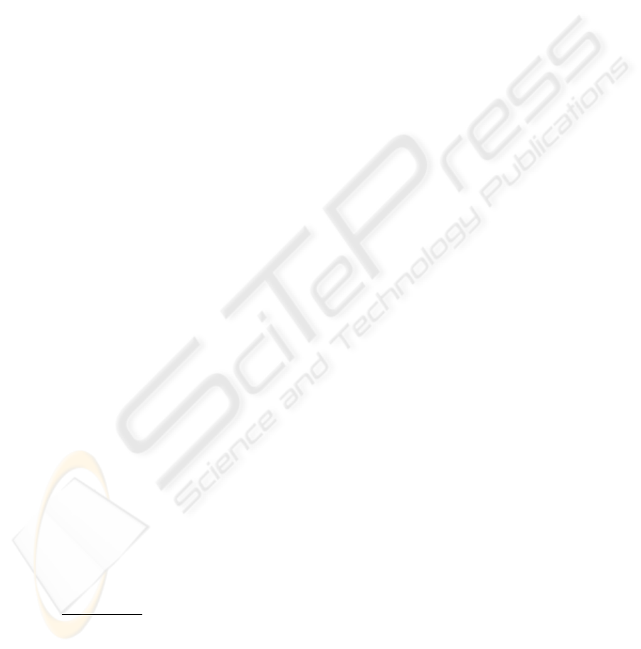
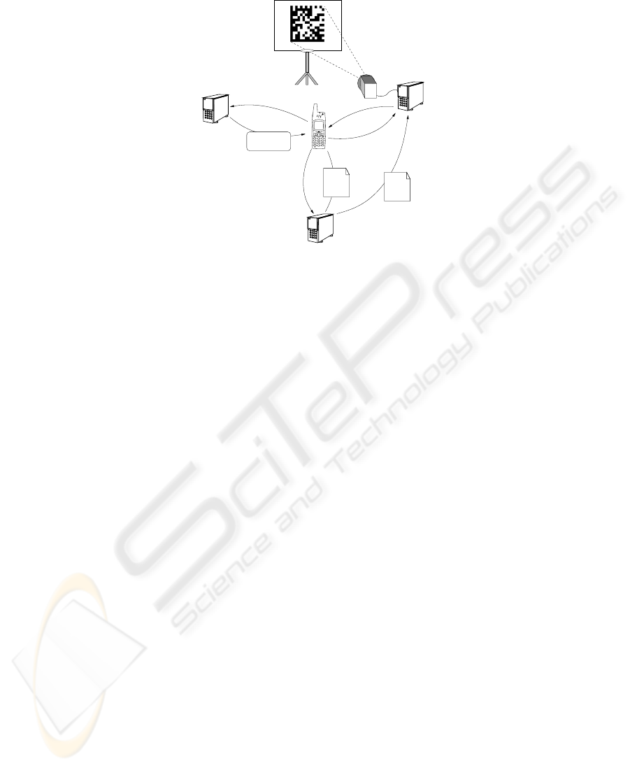
broker
User
Tag reader
Camera phone
Main GUI
Application
Resource
Repository
Custom
app
(a) System architecture
Camera phone
Custom
app
User
Resource
manager
Resource
(b) Interaction can be mediated by a manager
Fig.1. System architecture and interaction with a resource.
Figure 1(a) shows the main components of the system and the way they interact. The
main GUI visualizes a viewfinder that is used to center the tag and take a picture of it.
Then, the image is passed to the tag reader module that extracts the stored information.
The application broker module receives from the tag reader the name of the custom
application to start, the location of the application’s repository, and initial data.
Usually, once started, the custom application uses the network to interact with the
resource. Nevertheless, if the resource is not provided with computing/communication
abilities, interaction can occur through a resource manager (as shown in Figure 1(b)).
For example, let us suppose that a visual tag is attached to a door of an office, and that
a user, by taking a picture of the tag, can leave a virtual note to the owner of the office.
Since a door is not provided with any computing power, the custom application running
on the phone communicates with an ambient-server that represents the resource.
4 Downloading of New Applications and Passing of Parameters
Applications for MIDP devices, such as mobile phones, are packaged in form of jar
archives. Each archive contains a MIDlet suite, i.e. a set of one or more MIDlets, Java
programs defined as extensions of the MIDlet class. A MIDlet’s life-cycle is managed
by the application management software (AMS), that is part of the software operating
environment of the device. Installation of a MIDlet suite usually occurs by downloading
the archive through a GPRS/GSM connection, according to a standard procedure called
over-the-air provisioning (OTA). Custom applications that extends POLPO’s function-
alities are MIDlet suites that are downloaded and installed according to this procedure.
The only difference from standard MIDlets consists in the way they receive the para-
meters extracted from visual tags.
The application broker and custom applications belong to different suites and direct
communication is not possible (in the MIDP environment only one application at time
can be in execution, and method invocation is not allowed between classes that belong to
different suites). To overcome these constraints, we adopted a solution based on shared
information stored in the persistent memory. In the MIDP programming environment
the basic storage abstraction is the record store, a collection of records. A record store
is referred by a name, and a record is simply an unstructured array of bytes identified
43
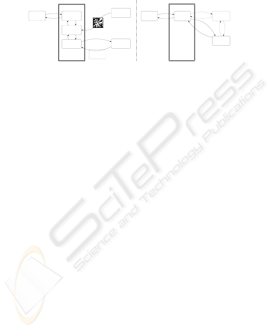
broker
Application
RMS
application
Custom
PrinterClient
Record store
IP = 131.114.9.94
Color = yes
Model = laser1
PrinterClient
Fig.2. Passing of parameters.
by a unique number. The Record Management System (RMS) is a set of classes that
provides methods to create/destroy record stores and to save/retrieve records in a record
store. As shown in Figure 2, the application broker creates a record store that has the
same name of the custom application that is going to be installed and writes into the
records the initial parameters that have to be passed to the application. When the custom
application is executed, it looks for a record store having the same application’s name
and, if any, reads the data.
With the exception of the initialization phase, custom applications can be designed
according to the standard J2ME guidelines. Therefore, programmers can make use of
all libraries provided by the Java runtime to build graphical user interfaces, to store data
into the persistent memory, or to communicate with external components through the
network or SMSs.
Since POLPO is based on the Java platform, execution of applications downloaded
from the network is safe. In fact, applications are executed in a sandbox and the JVM
security manager grants the privileges to access specific APIs on the base of levels of
trust. Moreover, the bytecode verification process guarantees that the application does
not perform any dangerous operation.
5 The Decoding Algorithm
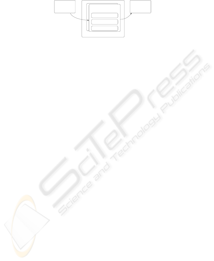
We implemented an algorithm to decode Data Matrix tags that is compatible with the
MIDP platform. Figure 3 illustrates the main steps of the process that localizes the
visual tag within the image. First, the RGB color image is converted to a gray-scale
image (Data Matrix symbols do not make use of colors). Then, the image is converted
to black-and-white through an adaptive threshold. To limit the computational overhead,
the threshold is set to the mean of the maximum and minimum values of luminance of
the image.
The next step consists in determining all groups of neighboring pixels that have the
same color. After the image has been divided into black or white regions, it is necessary
to identify the handles, i.e. the black solid bars that form two sides of the symbol. This
is done by determining some properties of each region and applying few empirical rules
(the candidate black area must be contained in a larger white area, the perimeter of the
candidate area must be larger than the others, etc.). The longest two segments in the
selected area are considered as the best approximation of the handles, and a precision
alignment technique is used to compensate the barrel distortion caused by the camera
44
Gray scale
conversion
Adaptive
thresholding
of connected
components
Labeling
Areas
Labelled
Preliminary processing
Symbol identification
of areas
Properties Best
candidate
Correction ofTwo longest
segments
Alternate pattern
alignement
Alignement
Bitmap
RGB
Edges of
the symbolbarrel distortion
Fig.3. Recognition algorithm.
Fig.4. Finding the alternate pattern.
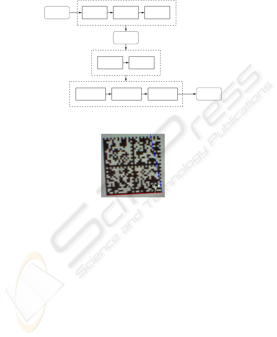
lens. To find the alternating pattern that forms the other two sides of the symbol, we
adopted the following procedure. Let us call P the end point of one of the handles. A
line is traced from P to each point of the border of a black area that is part of the symbol.
Then, the line that has the highest value for α is selected, where α is the angle between
the line and the handle (Figure 4). The same procedure is executed for the other handle,
and the intersection of the two selected lines is used to determine the missing corner of
the symbol.
Once the position of the symbol is known, the algorithm determines the number,
dimension and position of modules. This is done by locating the center of the modules of
the alternating pattern and building a sampling grid. Data modules are sampled at their
predicted center: black is a one, white is a zero. Groups of eight modules are converted
into 8-bit symbol characters, according to a positioning scheme defined by the Data
Matrix specification. Finally, after Reed-Solomon error correction, data is converted
according to a specific encoding scheme.
45
Primergy
Primergy
Primergy
3
1
2
7
6
5
4
Application repository
Host A
Host B
User’s homepage
Host C
BeamerServer
HTML
Beamer
Client
PDF
file
file
Fig.5. Video projector application.
6 Demonstrator Application
We developed a complete test application to demonstrate the architecture and the imple-
mentation of the POLPO system. The idea is to allow a user equipped with his mobile
phone to setup a slide show just by looking at, and taking a picture of, the projector
situated in a meeting room. We assume that the presentations are available through the
Web, for example at the user’s home page. On his arrival, the user selects the projector
by taking a picture of its screen, where a visual tag is displayed. Then the system re-
trieves the list of available presentations and the user is asked for the one to show. After
the presentation has been started, the user can use his mobile phone as a remote control
to visualize the next/previous slide or another presentation.
For such a scenario, Figure 5 shows the components involved and how they interact
with each other. The application that controls the projector is made up of two parts: a
suite composed by a single MIDlet, BeamerClient, that is executed on the mobile phone
and provides the graphical interface, and a server, BeamerServer, that is executed on
the computer connected to the projector and that displays the presentation. The system
works as follows.
i) The Data Matrix tag that is initially displayed by the projector contains the URL of
the repository of custom applications (Host A), the name of the custom application that
must be used to interact with the projector (BeamerClient), and the set of initializing
data (that consists of the name of the machine that controls the projector, Host B). When
the tag is decoded, the application broker (running in the mobile phone) creates an entry
in the RMS where it stores the address (Host B) that the BeamerClient application has
to use to interact with the projector. The BeamerClient.jar archive is downloaded from
Host A and installed.
ii) Once started, BeamerClient looks in the record store for an entry that contains the
name of the machine that controls the projector. BeamerClient also needs the URL of
46

the page that contains the links to the presentation files. To this aim it prompts the user
for the address (to make this task easier, the field is pre-filled with the URL of the user’s
homepage that is part of the personal data, so that a minimal amount of information has
to be edited).
iii) BeamerClient starts an HTTP connection and downloads from Host C the text of
the page that contains the presentations. Then BeamerClient parses the HTML file: all
href tags that point to files with a given extension (pdf in our implementation) are
considered as links to presentation files. The list of available presentations is built and
shown to the user who can select the one to visualize.
iv) The URL of the selected presentation is sent to BeamerServer, which retrieves the
pdf file and starts the presentation. Finally, BeamerClient shows a GUI that allows to
change the page displayed or the presentation: each command is forwarded to the Beam-
erServer which acts consequently.
Screenshots and a video of the demonstrator application are available at the follow-
ing address: http://vecchio.iet.unipi.it/polpo
7 Lessons Learned and Implementation Issues
In many cases, the portability of the Java language and the richness of the J2ME API
allowed us to develop the POLPO system in a relatively short time. For example, the
installation of a new application can be performed by calling the platformRequest()
method of the MIDlet class and passing as argument the URL of the jar archive. This
activates the AMS which starts the OTA installation procedure.
Nevertheless, in few cases, we found the application model of the MIDP profile
rather inflexible. In particular, the major issues came from two restrictions: i) a MIDlet
has no way to know if a given MIDlet suite is already installed or not; ii) a MIDlet is
not allowed to start a MIDlet that belongs to another suite.
The first restriction can be faced in two ways: either the application broker always
downloads and installs a custom application, possibly overwriting a previous installa-
tion, or the application broker manages a list of already installed custom applications.
Both solutions are not completely satisfactory: the former leads to unnecessary traffic
(e.g., BeamerClient has to be reinstalled every time the user interacts with a different
projector), the latter suffers of possible inconsistency of the application list (while cus-
tom applications are installed by the application broker, the deletion is directly managed
by the user).
The second restriction does not allow the application broker to automatically start a
custom application after the installation procedure. Therefore, the user has to manually
navigate through the set of installed applications and select the appropriate one.
During the implementation, we experienced some problems because of the Mobile
Media API (MMAPI) optional package, that enables easy access and control of mul-
timedia resources. In particular, the problems were due to the implementation of the
getSnapshot() method which must be used to capture pictures through the camera in a
platform independent way: two models of mobile phones that we used were equipped
with VGA cameras, but they were able to capture images only with a resolution of
47
160x120 pixels (instead of 640x480 as possible with native applications). This problem
is also described in [10].
The size of the Data Matrix decoder is approximately 4400 lines of code, while
the size of the main GUI and the application broker together is less than 1000 lines
of code. Once compiled, the size of the jar archive that includes the GUI, the decoder,
and the application broker is approximately 70KB (without obfuscation). The jar of the
BeamerClient is less than 10KB.
8 Conclusion
Until the coming of new technologies able to modify the way users interact with the
world that surrounds them, mobile phones will remain the platform of choice for the
development of pervasive applications. While some research has already been done
on how using camera phones as a platform for pervasive computing, we believe that
POLPO is a step forward in the direction of delivering site-specific services to the real-
world: since it is based on the J2ME platform, the share of end users is significantly
larger than the one offered by other systems.
In addition, as far as we know, POLPO is the first platform that supports dynamic
downloading of new applications on mobile phones. The expandability of the software
installed on the user’s device is a key factor in a pervasive computing scenario: the set of
services available to the users must grow as new devices or software systems are added
to the environment. If the functionalities of the system are statically defined, users are
forced to upgrade their devices continuously.
References
1. Weiser, M.: The Computer for the 21st Century. Scientific American 3 (1991) 94–104
2. Abowd, G., Iftode, L., Mitchell, H.: The smart phone–a first platform for pervasive com-
puting. IEEE Pervasive Computing. Special Issue: The Smart Phone: A First Platform for
Pervasive Computing 4 (2005)
3. http://www.infotrends-rgi.com.
4. Rekimoto, J., Ayatsuka, Y.: Cybercode: designing augmented reality environments with
visual tags. In: DARE ’00: Proceedings of DARE 2000 on Designing augmented reality
environments, New York, NY, USA, ACM Press (2000) 1–10
5. Rohs, M.: Real-world interaction with camera-phones. In: 2nd International Symposium on
Ubiquitous Computing Systems (UCS 2004), Tokyo, Japan (2004) 39–48
6. Toye, E., Sharp, R., Madhavapeddy, A., Scott, D.: Using smart phones to access site-specific
services. IEEE Pervasive Computing 4 (2005) 60–66
7. Iso, T., Isoda, Y., Otsuji, K., Suzuki, H., Kurakake, S., Sugimura, T.: Platform technology
for ubiquitous services. (NTT Technical Review) 82–88
8. Iso, T., Kurakake, S., Sugimura, T.: Visual-tag reader: image capture by cell phone camera.
In: Proceedings of International Conference on Image Processing (ICIP). (2003)
9. International Organization for Standardization/International Electrotechnical Commission:
(International Symbology Specification - Data Matrix, Bar code symbology – PDF417, Bar
code symbology – QR Code, International symbology specification – MaxiCode)
10. Tierno, J., Campo, C.: Smart camera phones: Limits and applications. IEEE Pervasive
Computing. Special Issue: The Smart Phone: A First Platform for Pervasive Computing 4
(2005)
48
