
Validation of Visual Contracts for Services
José D. de la Cruz
1
, Lam-Son Lê, Alain Wegmann
School of Computer and Communications Sciences
Ecole Polytechnique Fédérale de Lausanne
CH-1015 Lausanne, Switzerland
Abstract. Visual modeling languages have specialized diagrams to represent
behavior and concepts. This diagram specialization has drawbacks such as the
difficulty in representing the effects of services (or actions). We have developed
a Visual Contract notation that describes, within one diagram, a service and its
effects. This paper presents the semantics of this notation and the verification
and validation capability provided by the mapping between our notation and the
Alloy lightweight specification language. This validation and verification capa-
bility of the Visual Contracts contributes to business/IT alignment.
1 Introduction
One of the important trends in business/IT alignment is service specification. Services
can represent the responsibilities of companies in their market, of IT systems in busi-
ness processes, or of software components in IT systems. Our Visual Contracts pro-
vide a graphical representation of services [1]. To be able to verify and validate these
service specifications, it is important to define the semantics of the Visual Contracts.
This is the goal of this paper. The semantics is defined by providing a mapping to the
Alloy specification language [2]. The Alloy Analyzer tool can then be used to verify
and validate the specification. For the verification, the modeler tests whether an in-
stance model can be generated from the service specification (i.e. the Visual Contract
has no inconsistencies). For the validation, the modeler asks the service’s stakeholder
to check if the instance models generated by the service “execution” on the Alloy
Analyzer tool correspond to the business needs.
Throughout the paper we will show the example of an IT system (BoardingIT-
System) that controls the boarding process of passengers on an airplane. Initially,
the aircraft is empty. Then the systems processes the requests from passengers that
ask to go onboard; passenger admission requests are processed one by one until the
aircraft’s maximum capacity is reached. As a safety rule, none of the passengers can
board or disembark more than once.
Section 2 introduces the Alloy specification language. Section 3 defines the Visual
Contract primitives and their semantics (in Alloy). Section 4 presents the Visual Con-
tracts for the BoardingITSystem example and demonstrates how our approach
enables their verification and validation. Section 5 describes the state of the art.
1
This work was partially supported with grants from the CFBE and the EPFL-SOC.
D. de la Cruz J., Lê L. and Wegmann A. (2006).
Validation of Visual Contracts for Services.
In Proceedings of the 4th International Workshop on Modelling, Simulation, Verification and Validation of Enterprise Information Systems, pages
147-156
DOI: 10.5220/0002502501470156
Copyright
c
SciTePress

2 Alloy Specification Language and Tools
Alloy Analyzer[2] is a tool for performing automatic verification of software specifi-
cations. The Alloy analyzer is built on a SAT prover. As such it can generate in-
stances of models that correspond to a specification (and hence, check that the speci-
fication has no inconsistency). It can also check model properties.
A system specification in Alloy is composed of the following parts:
• signatures (keyword “sig”): declares types, sets and relations among types
• facts: global constraints, invariant properties
• functions: parameterized constraints
• assertions: theorems to check, concerning system properties
• commands: run function and/or check assertion
We will visually identify these parts in the definition of semantics of the Visual Con-
tracts. The signatures and facts describe the structural and invariant properties of the
system. The functions describe the dynamics of the system. The model checking is
done by “executing” the functions and assertions found in the commands section; this
will be explained and illustrated further in section 4.2.
3 Visual Contracts
We define Visual Contract (VC) as the visual model that represents both the pre-
and the post-conditions for an action, and that makes explicit the changes from the pre
to the post state. Our Visual Contract notation is developed in the context of the
SEAM notation. SEAM (Systemic Enterprise Architecture Methodology) is a method
designed for reasoning about business and IT alignment [3]. A more detailed defini-
tion of Visual Contracts and related concepts is found in [1].
3.1 Basic Concepts
In our approach, we model the behavior together with the state of the systems. Sys-
tems are modeled as working objects. A working object has information objects (that
define possible states), set associations (that define instances) and actions (that change
the state of the instances represented on the set associations).
Information Objects. An Information Object (IO for short) is equivalent to a prop-
erty of the system. It captures the type of the possible states of the observed system.
The symbol in figure 1 represents a generic information object.
Generic_IO
attrib1
attrib2
id
Generic_IO {
id: Int,
attrib1: Int,
attrib2: Int
// Int (integer) is a
// built-in type in Alloy
}
SIGNATURE OF
TYPE
G
ENERIC_IO
Fig. 1. Symbol and Alloy specification for the Information Object Generic_IO.
148
Each instance of an IO has an identity, encoded in the attribute id. As this is a de-
fault attribute, we will omit it in diagrams except when absolutely necessary.
By extending our visual notation, we can also represent state information. We
show this in figure 2 for the IO Person – that will be used in the example—. The
bold line around the attribute boarded means that its state specification is complete:
the only possible states of boarded are offBoard and onBoard.
Person
offBoard onBoardboarded
sig BoardingState {}
one sig OnBoard extends BoardingState {}
one sig OffBoard extends BoardingState {}
sig Person
{ id: Int,
boarded: one BoardingState
}{
boarded in (OnBoard + OffBoard)
}
SIGNATURE OF
TYPE PERSON
SIGNATURE OF TYPE
B
OARDINGSTATE
FACTS OF
TYPE PERSON
Fig. 2. Extended notation and Alloy equivalent for the Information Object Person. In the ex-
tended notation the state information of the IO is included.
Set-Associations. Relationships between information objects are represented as set-
associations (SA). The purpose of set-associations is to capture information about in-
stances. The instances of the IOs exist only in the context of SAs.
Irina: Person
HK007
:Aircraft
passenger1
Angela: Person
passenger2
Gil: Person
passenger3
Lam-Son: Person
passenger4
Ob
j
ect
diagra
m
State diagra
m
offBoard
onBoard
[disembark]
[embark]
class Person
Fig. 3. UML object diagram for 4 passengers and state diagram for the class Person.
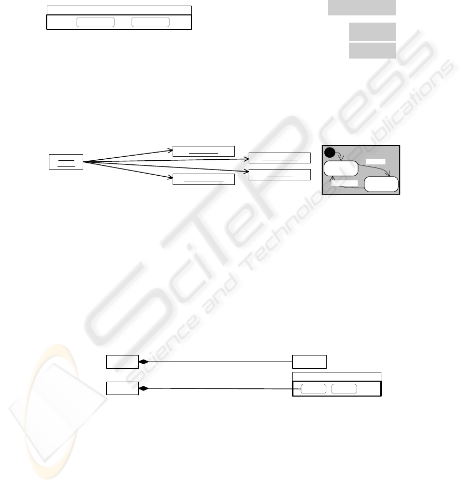
We can give an intuitive feeling of our approach, with a UML [4] example (Figure 3)
representing 4 people (Irina, Angela, Gil and Lam-Son) who are on the
list of passengers of an aircraft. As the state diagram shows, the Person can be ei-
ther onBoard or offBoard hence two lists are required. This is an implicit re-
quirement of the problem that is not visible in the UML specification (figure 3).
In UML, it is not clear how to instantiate the state information of objects. How-
ever, we just saw that we must include state information in order to differentiate the
lists of passengers– one for offBoard (at the dock), and another for onBoard (al-
ready on the plane)–. Two of the options to represent the instance (object+state) in-
formation in one diagram are shown in Figure 4.
#4
passenger_List
Aircraft
Person
{ state = onBoard }
{ Irina, Angela }
{ Gil, Lam-Son }
Aircraft
passenger_List
{ HK007 }
b)
a)
Person
offBoardonBoard boarded
Fig. 4. SEAM representation of 4 passengers using (a) instance identifiers and (b) instance car-
dinalities + explicit IO state information.
Actions. An action is the modeling element that specifies the effects of system’s re-
actions to a set of events for a given system state. It is equivalent to a service.
149
Contexts of Existence. We have already said that all SAs constitute the context
where instances actually exist. This adds a temporal frame for reasoning about the
system and, in particular, what happens when an object is deleted. We distinguish two
cases:
− Tight binding (filled diamond, as in figure 4): the instances actually exist in the
SA, and whenever the SA (or the referencing IO) is deleted, the instances are de-
leted, too.
− Loose binding (hollow diamond): the instances are only referenced. This means
that when the SA is deleted (or the referencing IO), the actual instances are not de-
leted but their references do.
Parameters. We define a parameter as a special information object used either to
communicate through the boundary of the system or among action boundaries. Every
parameter is either consumed by another action or sent to the environment. A parame-
ter is represented by a stereotyped IO. The stereotype label can be «Par In» or «Par
Out».
Select Operator. Very often we will have to select subsets from an original set. The
«select» operator allows us to do this. It describes visually how a set (set-association)
is created from another SA. It is drawn as a box containing a predicate (filter), linking
the source set, the filter set and the target (resulting) set, as shown in figure 9.
3.2 Building Correct-by-Construction Systems
First, by introducing state information, the modeler extracts additional requirements.
For instance, we elicited a hidden requirement that says that there are two lists of pas-
sengers (and two lifecycles): one for onBoard, and another for offBoard.
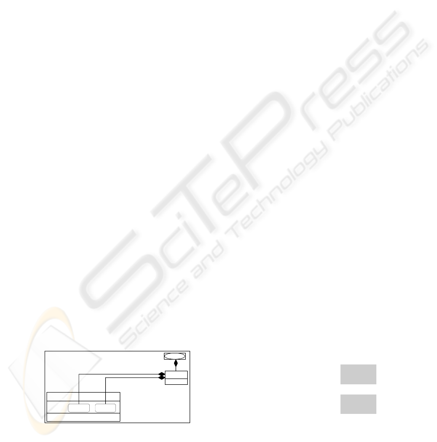
Second, the reasoning process takes into account lifecycles because we make ex-
plicit the contexts of existence. In figure 5, the system itself is represented –via the IO
Myself—since it permits establishing how many instances of each IO are present in
a single system. Thus, one Plane exists in the context of BoardingITSystem.
Then, 2 lists of Person (passenger) exist in the context of a single Plane (i.e. SAs
onBoard_passenger_List and offBoard_passenger_List). Last, mul-
tiple instances of Person may exist in the context of each Passenger_List.
Third, since almost all IOs correspond to physical systems, when reasoning we can
take into consideration the fact that the sets must be limited by the capacities of IOs.
This is why the Plane (IO in the IT system) has an attribute Capacity.
one sig Plane {
capacity: Int,
onboard_passenger_List: set Person,
offboard_passenger_List: set Person
} {
int capacity > 0
int capacity >=
#onboard_passenger_List + #offboard_passenger_List
all p: Person |
p in onboard_passenger_List => p.state = OnBoard
all p: Person |
p in offboard_passenger_List => p.state = OffBoard
no p: Person |
p in onboard_passenger_List and p in offboard_passenger_List
}
BoardingITSystem
# *
capacity
Plane
Myself
#1
Person
onBoard offBoard
id
# *
offBoard_passenger_List
onBoard_passenger_List
Boarded
SIGNATURE OF
TYPE PLANE
FACTS ABOUT
TYPE PLANE
Fig. 5. SEAM notation for property definitions in the BoardingITSystem specification.
150

Modeling Change via the Set-Associations. Our set-associations evolve over time
by changing their states (number of IOs and state of IOs in the set). We distinguish
three main classes of SAs:
• IO-IO: as described until now, it makes explicit relationships between IOs.
• Action-IO: it allows describing instances that exist only during an action.
• SA-SA: equivalent to a simple relational algebra among SAs (sets).
To give an intuition of state change of set associations, let us model a system that has
one instance of Person that is offBoard at the beginning (@pre) of an action
op1; at the end (@post) of the same action, the system has one instance of Person
in state onBoard. Figure 6 shows the UML way to represent this scenario. Part a
corresponds to the pre-condition (@pre) and part b corresponds to the post-condition
(@post). Figures 6.a and 6.b are identical. No change is noticeable.
We argue that this happens because UML diagrams are not tightly coupled. The ac-
tion and the object instances are linked implicitly
. A textual OCL document may be
added to the model in order to make explicit the changes due to action op1.
op1
a)
:Person
State diagram
offBoard
onBoard
[disembark]
[embark]
class Person
Snapshot@pre Activity diagram
Person
Class diagram
Aircraft
1
1..*
candidate
1
1..*
passenger
BoardingITSystem
op1
b)
:Person
State diagram
offBoard
onBoard
[disembark]
[embark]
class Person
Snapshot@post Activity diagram
Person
Class diagram
Aircraft
1
1..*
candidate
1
1..*
passenger
BoardingITSystem
Fig. 6. UML object, activity, state and class diagrams for a) before and b) after action op1. The
effect of action op1 is not evident.
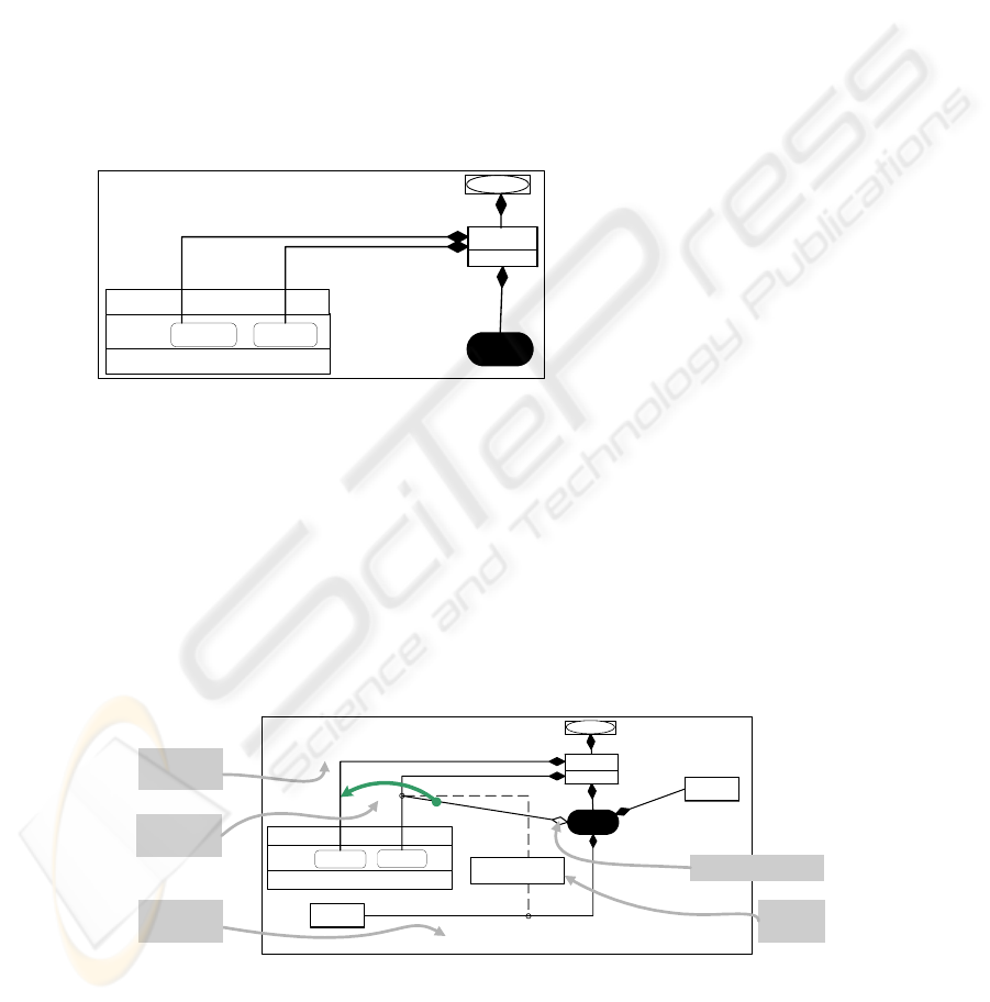
Compare figures 6 and 7. Figure 7 is the Visual Contract of action op1. It shows
the action and the objects in a single diagram (tight coupling). We can now write as-
sertions about this action and the configurations of objects. The brackets identify the
predicates that are necessary conditions (pre-conditions) for the changes to take place.
Initially, the SA offBoard_passenger_List includes one instance of IO
Person that is offBoard. At the end, the same Person IO instance is onBoard.
Figure 7 summarizes this state change using the «change» operator (Æ) for cardinal-
ities and a «transfer» operator (curved, wide arrow) between lists. However, we need
to provide a mechanism to indicate what instances should be affected
(changed/transferred) for complex cases (i.e. the offBoard_passenger_List
consists of more than one instance of Person). This will be discussed in section 4.1.
BoardingITSystem
[#0] -> #1
capacity
Plane
Myself
#1
Person
onBoard
offBoard
offBoard_passenger_List
onBoard_passenger_List
Boarded
op1
«Transfer»
Operator
Pre-condition
Brackets
«Change»
Operator
[#1] -> #0
Fig. 7. Action changes the cardinality of both SAs for passenger lists. A transfer has been
made, meaning also a change of state of the respective instances of IO Person.
151
4 Verification, Simulation and Validation of the Specification
In this section, we describe how to “execute” the services specified via the Visual
Contracts. The instance models resulting from the verification can then be used by the
stakeholders to validate the services.
4.1 Visual Contracts for Actions Init and Board
Figure 8 shows the SEAM Visual Contract for operation Init. It states that: “The
aircraft is initially empty”; in other words, the number of Person in the on-
Board_passenger_List is set to zero, as shown in the VC in figure 8. This
means that the cardinality of SA onBoard_passenger_List goes from some
initial value (any, symbolized by the character ‘*’) to 0.
Init
BoardingITSystem
[# *] --> #0
capacity
Plane
Myself
[#1]
Person
onBoard offBoard
id
# *
offBoard_passenger_List
onBoard_passenger_List
Boarded
// Init empties the plane
pred Init (a: one Plane, post: Time)
{
no a.onboard_passenger_List.post
}
Fig. 8. Visual Contract for action Init and the corresponding Alloy code.
The operation Board is more complex. The specification is the following: “The
preconditions are: a) an input parameter represents the person that desires to go on
board, b) this person is not on the list of persons that are already onboard, and c) the
number of people onboard has not reached the maximum capacity of the aircraft. The
post-condition are a) this person is now onboard, b) the system emits a message con-
firming the entry of this person onto the plane”.
The Visual Contract for Board is shown in figure 9. The intermediate processing
is kept in the final contract in order to make the changes more understandable: the
passenger id is validated and the instance is selected via the SA selected. Note
that the constraint regarding the aircraft capacity (precondition c) is the guard for
transferring –and for changing the state of— the instances from SA selected.
Board
Id_Person
<<Par In>>
[#1] -> #0
valid
Valid = one (Persoin.id
== Id_Person)
BoardingITSystem
[# *] -> # (*+1)
capacity
Plane
Myself
offBoard_passenger_List
[#1]
Person
onBoard
offBoard
id
[# *] -> # (*-1)
onBoard_passenger_List
selected
Response
<<Par Out>>
[#0] -> #1
Greetings_Response
[notFull]
notFull = onBoard_passenger_List.cardinality < Aircraft.capacity
Boarded
«Select»
Operator
«Change»
Operator
Guard for
«Transfer»
Operator
Resulting Subset Of
«Select» Operator
Guarded
«Transfer»
Operator
Fig. 9. Visual Contract for action Board. It illustrates the operators «select», «change», and
«transfer».
152

4.2 Alloy code and Analysis for Actions Init and Board
In order to write an Alloy equivalent of the Visual Contract for action Board, we
have to introduce the notion of time.
Modeling time. We model time as an ordered vector. Time enables differentiating
the model instances before and after every action is executed. Figure 10 shows the
Visual Contract code of action Board already modified for modeling time.
open util/ordering[Time]
sig Time { }
sig BoardingState {}
one sig OnBoardState, OffBoardState extends BoardingState {}
sig Id_Person {}
sig Person {
id: Id_Person,
state: BoardingState one -> Time
}
fact uniqueID { all p, q: Person | p != q <=> p.id != q.id }
one sig Plane {
capacity: Int,
onboard_passenger_List: set Person -> Time,
offboard_passenger_List: set Person -> Time
} {
all t: Time | all p: Person | p in onboard_passenger_List.t => p.state.t = OnBoardState
all t: Time | all p: Person | p in offboard_passenger_List.t => p.state.t = OffBoardState
all t : Time | int capacity >= #onboard_passenger_List.t + #offboard_passenger_List.t
all t: Time | no p: Person | p in onboard_passenger_List.t and p in offboard_passenger_List.t
all t: Time | all p: Person | p !in onboard_passenger_List.t => p in offboard_passenger_List.t
}
pred Board (ps: set Id_Person, a: one Plane, pre, post: one Time) {
pre != post
// pre-condition
all pid : ps | one p: Person | p.id = pid and p in a.offboard_passenger_List.pre
// post-condition
let psl = { p: Person | p.id in ps } |
// onboard list increased
a.onboard_passenger_List.post = a.onboard_passenger_List.pre + psl and
// offboard list decreased
a.offboard_passenger_List.post + psl = a.offboard_passenger_List.pre
}
SIGNATURE OF
STATE TYPE
SIGNATURE OF
TYPE PERSON
FACTS / CONSTRAINTS ABOUT PERSON IDS
SIGNATURE OF
TYPE PLANE
FACTS ABOUT
TYPE PLANE
ACTION BOARD IS A
T
HEOREM TO PROVE
@Pre:
Person with
id=Id_Person is
offBoard
@Post:
Person with
id=Id_Person is
onBoard
Fig. 10. Alloy equivalent of the Visual Contract for action Board.
Verification. In order to create a complete basic scenario we must ask the Alloy
Analyzer to do an action Init followed by one or several actions Board (action
Init_and_Board), as shown in figure 11. It is essential to guarantee a minimum
size of the state space, in order to avoid the trivial solutions.
The Alloy Analyzer tool creates all the model instances that can be generated from
this scenario. First, the Alloy Analyzer tool will generate all the instances in the de-
fined scope. Second, it will verify the Visual Contracts by finding all generated in-
stances that are inconsistent with the VCs under study. Last, if any instance is found
to be inconsistent (i.e. two or more constraints are incompatible or contradictory), the
Alloy analyzer can generate counterexamples that illustrate the inconsistencies.
153
pred Init (a: one Plane, post: one Time) {
no a.onboard_passenger_List.post
// at least 3 people are offboard at the end of action Init
#a.offboard_passenger_List.post > 2
}
pred Init_and_Board (ps: set IDPerson, a: one Plane, pre, post: one Time) {
#ps = 2
post = next(pre)
Init (a, pre) and Board (ps, a, pre, post)
}
run Init_and_Board for 5 but 2 BoardingState, 2 Time
SCENARIO SET-UP:
F
IRST INIT THEN, BOARD
Establish causality or sequence
and then prove the theorems
Determine the Scope of State
Space for the Model-Checker
ACTION INIT IS A THEOREM TO
P
ROVE
Nobody is onBoard, but we need someone
offBoard or the verification will be useless
Fig. 11. Alloy code for performing the model-checking of the specification of figure 10.
Simulation and Validation. The Alloy Analyzer will explore the constrained state
space of instances for each object as indicated in the last line of the code in the figure
11. The tool will execute the sequence (action Init followed by action Board) and
check that all the instances in the scope respect the constraints.
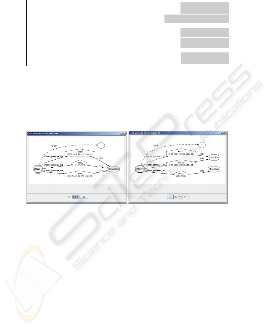
We extract the snapshots since they allow us simulating the behavior of the system
in time. Each of the time points correspond to one point in a vector. We project the re-
sulting instance models in time, in order to retrieve an ordered sequence of snapshots.
Fig. 12. Results of simulating the action Board in the Alloy analyzer. At Time_0 the passengers
(Person0, Person1, and Person2) have already checked-in. At Time_1 two of them (Person0,
Person1) have effectively embarked on the plane. Capacity of the plane is 3.
Finally, it is the user who validates the service: she can see the results of this simula-
tion and decide whether the behavior is adequate or not. Two resulting snapshots of
the simulation are shown in figure 12. These instance models can now be discussed
with the stakeholders to validate the service specification.
5 Related Work
UML [4] is the industry standard in object-oriented analysis and design. UML pro-
vides a rich set of notations. Relating these notations is often the responsibility of the
designer. But its diversity is a potential source of misunderstandings and errors in the
implementation of the system [5, 6]. In our approach, we try to minimize this problem
154

by representing conceptual and behavioral specifications in one diagram. For this, we
extend the initial proposition of [7] to include state information in the class diagrams.
The use of contracts for object oriented (OO) programming approaches [8, 9] was
followed by the use of contracts in OO methods [10, 11], using a textual notation for
the logics. Only recently [12, 13] have independently proposed the concept of “visual
contracts”. Work by [12] focuses on the generation of executable code that can per-
form run-time verification of constraints; our approach is declarative, allowing us to
execute and evaluate very high-level model specifications.
Notations used for workflow systems [14, 15] represent specifications of actions
mainly in natural language; therefore, they are user-friendly but not directly translat-
able in terms of what changes in the information system (IS). Our approach is also
visual but attempts to make explicit the effects of services in terms of the supporting
IS, facilitating the subsequent automation and setting a more concrete reasoning
framework.
Finally, a Visual Contract cannot be compared to an UML snapshot because a Vis-
ual Contract is generic: It can be applied to a whole family of snapshots and even sce-
narios. Furthermore, the similarity with other diagrammatic works –such as the graph
transformation languages—is only apparent since their foundations are orthogonal to
our systemic approach, and our goal is to add semantic content to visual specs.
6 Conclusions and Future Work
Business/IT alignment requires specifying services. We propose SEAM Visual Con-
tracts as a means to specify services. The verification and validation requires either
testing (manual and not complete) or model checking (automatic and theoretically
complete). We propose a mapping between our visual contracts and Alloy, a light-
weight formal language. Thanks to this, it is possible to use the Alloy Analyzer as
model checker in order to verify, validate and even simulate the Visual Contracts.
The main advantages of SEAM Visual Contracts are:
• They are not IT specific. They can represent services of companies, departments,
IT systems, etc [3]. This makes them applicable as well to business processes [15]
specification.
• They can be validated and verified at a high level of abstraction. This reduces the
time when compared to testing specific, full-fledged implementations[2].
• They are UML-like [4]. Thus, UML practitioners may adopt them quickly.
Our future work includes defining how to express the contexts of existence, develop-
ing CAD tool support [16] for automating the translation process, and validating the
approach usability in concrete projects. At present we are developing a tool for trans-
lating UML specifications to VCs and evaluating a technique to refine VCs.
References
1. De la Cruz, J. D., Lê, L.-S., Wegmann, A.: VISUAL CONTRACTS: A way to reason
about states and cardinalities in IT system specifications. In: Proc. 8th International Confer-
ence on Enterprise Information Systems - ICEIS 2006 (2006) Accepted for publication
155

2. Jackson, D.: Alloy: a lightweight object modelling notation. ACM Trans. Softw. Eng.
Methodol. 11 (2002) 256-290
3. Wegmann, A., Balabko, P., Le, L.-S., Regev, G., Rychkova, I.: A Method and Tool for
Business-IT Alignment in Enterprise Architecture. In: Proc. CAiSE'05 (2005)
4. OMG. (2004) Unified Modeling Language: Superstructure 2.0 Final adopted specification,
ptc/03-08-02.[Online]. Available: http://www.omg.org/docs/ptc/03-08-02.pdf
5. Dori, D.: Why significant UML change is unlikely. Communications of the ACM (CACM)
45 (2002) 82-85
6. Argawal, R., Sinha, A. P.: Object-oriented modeling with UML: a study of developers' per-
ceptions. Communications of the ACM (CACM) 46 (2003) 248-256
7. Rumbaugh, J. R., Blaha, M. R., Lorensen, W., Eddy, F., Premerlani, W.: Object-Oriented
Modeling and Design. Prentice Hall (1991)
8. Meyer, B.: Applying "Design by Contract". IEEE Computer 25 (1992) 40-51
9. Helm, R., Holland, I. M., Gangopadhyay, D.: Contracts: Specifying Behavioural Composi-
tions in Object-Oriented Systems. In: Proc. OOPSLA/ECOOP 1990 (1990) pp. 169-180
10. Wirfs-Brock, R., Wilkerson, B., Wiener, L.: Designing Object-Oriented Software. 1 edn.
Prentice Hall, Englewood Cliffs (1990)
11. D'Souza, D. F., Cameron Wills, A.: Objects, components, and frameworks with UML: The
Catalysis approach. 1 edn. Addison Wesley Longman, inc. (1998)
12. Lohmann, M., Sauer, S., Engels, G.: Executable Visual Contracts. In: Proc. IEEE
VL/HCC’05 (2005)
13. De la Cruz, J. D., Wegmann, A., Regev, G. Expressing Systemic Contexts in Visual Mod-
els of System Specifications. CEUR Workshop Proceedings [Online]. Available:
http://sunsite.informatik.rwth-aachen.de/Publications/CEUR-WS//Vol-
144/04_deLaCruz.pdf
14. (WfMC), W. M. C. (2005) WfMC Documents and Interfaces.[Online]. Available:
http://www.wfmc.org/standards/standards.htm
15. OMG. (2005) Business Process Modeling Notation (BPMN) Information.[Online]. Avail-
able: http://www.bpmn.org/
16. Le, L. S., Wegmann, A.: Definition of an Object-Oriented Modeling Language for Enter-
prise Architecture. In: Proc. Hawaii International Conference on System Sciences
(HICSS'05) (2005) 222-231
156
