
ARCHITECTURE FOR A REMOTE ACCESS LABORATORY
WITH APPLICATION TO ELECTRONICS ENGINEERING
TEACHING
Marco Túlio Chella and Elnatan Chagas Ferreira
Universidade Estadual de Campinas, Caixa Postal : 6101, Barão Geraldo, Campinas, Brasil
Keywords: Laboratory, Remote, Internet, education, distance.
Abstract: This article presents an architecture for the development of Internet remotely controlled experiments with
focus on educational applications. We use the Internet as the communication infrastructure; hardware and
applications specific for computer based instrumentation; a system composed of an electronic board and
applications for monitoring and controlling real experiments. The experiments created with the tools
presented make it possible for a user with a computer connected to the Internet to control and get
information about the experiment upon which he/she is acting.
1 INTRODUCTION
Remote laboratories are real equipment, which can
be remotely operated and controlled by means of a
graphical interface, usually employing the Internet
as means of communication. A remote laboratory
simplifies the logistics and infrastructure required
for the operation of a conventional laboratory, such
as equipment scheduling, physical space and
professionals for surveying students’ activities.
From the educational point of view, when students
have freedom to conduct experiments from any
computer connected to the internet at the most
convenient times for him/her, the learning process
begins to take place as a function of the student’s
rhythm and availability of time (D’Abreu, 2003).
2 MOTIVATION
Besides the theoretical instruction based on
traditional classes, the experience of doing things
practically provided by laboratories are vital
elements for the education of engineering
professionals (Hua & Ganz, 2003). However,
arranging and keeping available a laboratory for
long periods of time may signify a high financial
cost. With a remote laboratory it is possible to
optimize the use of resources as it may be available
for longer times and may be accessible to more than
one educational institution and consequently to a
greater number of students, who may simultaneously
participate on experiments at different places and
times.
Another aspect to consider is that, as there is no
need for the students to be physically present in the
laboratory, there is no need of facilities with large
physical space and this may signify a reduction in
maintenance costs.
By providing them access to remote experiments,
one can satisfy the existing demand for teaching
students the use of complex technical equipment,
introducing them to the state-of-the-art practices of
their fields of study and fulfilling the expectations
about what is expected in their education. In giving
them access to experiments high cost and sometimes
sensible equipment, one may expand the range of
utilization of such equipment obtaining, in a certain
sense, economies of scale (Schafer, Seigneur &
Donelly, 2002).
From the educational point of view, it is believed
that all learning processes that may possibly be
conducted within a local environment may also be
realized remotely, an approach which, unlike the
traditional classroom, involves communication and
knowledge based on freedom, plurality and
cooperation in the largest possible scale (Silva,
2000).
Several universities and research centers around
the world have developed works concerning the
remote control of instruments through the Internet.
403
Túlio Chella M. and Chagas Ferreira E. (2007).
ARCHITECTURE FOR A REMOTE ACCESS LABORATORY WITH APPLICATION TO ELECTRONICS ENGINEERING TEACHING.
In Proceedings of the Third International Conference on Web Information Systems and Technologies - Society, e-Business and e-Government /
e-Learning, pages 403-408
DOI: 10.5220/0001272204030408
Copyright
c
SciTePress
Some, as Telelab (Casini, Prattichizzo & Vicino,
2002), AIM (Shen et al. 1999) and PEARL (Schafer,
Seigneur & Donelly, 2002) were designed with
educational goals.
The various remote laboratory systems studied
exhibit a common feature: they were developed by
researchers skilled on the several technologies
related to the programming of Internet applications
and with deep knowledge of hardware and of the
network and communication protocols of the
instruments entering their environments.
Consequently, such systems are monolithic, offer
little flexibility and are difficult to be modified by
users.
3 OBJECTIVE
Our goal in developing a tool for creating remote
experiments is to provide teachers with resources for
designing their experiments, which may involve
controlling instruments and activating relays,
electronic switches and digital potentiometers,
among other devices, without concern to the
problems related to programming instruments,
hardware communication and their integration to the
Internet, being able to focus on the aspects related to
the subject they want to explore.
The contribution of this work is the development
of a platform for supporting experiments in the field
of electronics, on which it is possible to perform,
remotely and locally, several distinct experiments
conceived and performed in real laboratories and
satisfying the following characteristics:
A low and decreasing per student cost: after the
initial investment, the remote laboratory tends
to become more economical as compared with
the conventional one, as it can serve a greater
number of students.
Modularity, in the sense that it allows the
addition of new experiments, equipaments and
applications.
Experiments are performed in real time.
Possibility of employing experimental
procedures already existing in conventional
laboratories, being easily integrated to other
educational resources used such as textbooks
and pictures, among others.
Applicable in remote and local modes.
Shared access to high cost equipments,
rendering unnecessary their acquisition by
each institution or laboratory.
Flexible scheduling for performing the
experiments, optimizing the students’ study
hours and the use of the equipments.
Resources for integration to systems for
creation and management of courses in E-
learning such as Aulanet (2003) and Teleduc
(2003).
4 ARCHITECTURE OF THE
REMOTE LABORATORY
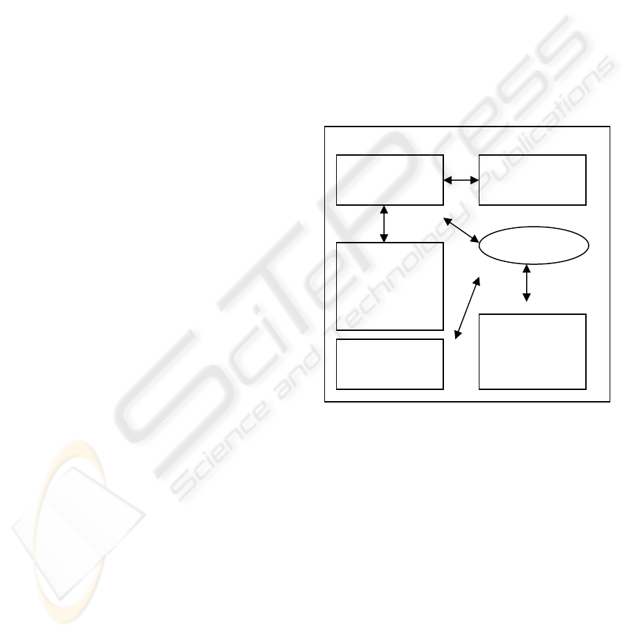
In order to achieve the objective proposed, the
remote laboratory system, composed by an
integrated set of applications and modules, has been
implemented (figure 1).
Figure 1: Diagram of Remote Laboratory.
In what follows we describe the main components of
the remote laboratory’s architecture.
Experiment Board - An electronic board
containing the electronic circuit that will be
used for the experiment, it is endowed with
connections for inserting the Electronic
Blocks, which permit the variation of the
various circuit parameters.
Electronic Blocks - Electronic circuits playing
the functions of the main components used in
electronics, such as potentiometers, electronic
switches and resistors, among others. The
electronic blocks receive the commands
originated in the computer and converted in
the control board, and thus modify their states
and values.
Experiment
Server
Experimen
t Editor
Hardware
(control and
experiment
b
oards)
Interne
t
GPIB
Server
Remote
Experiment
Client
WEBIST 2007 - International Conference on Web Information Systems and Technologies
404

Control Board - Electronic circuit connected to
the computer through the USB port, it is
responsible for receiving the activation and
control commands which come from the
application running on the PC and acting upon
the electronic blocks on the experiment board.
Experiment Editor - An application used by the
developer of the remote experiment. It
employs a graphical interface composed of a
working area and a toolbar, and allows the
user to select the Electronic Blocks and
graphical objects that will be used in the
experiment and to dispose them on the
working area by dragging and dropping.
Clicking the right mouse button opens a box
in which it is possible to assign values to the
properties available in each Electronic Block
and graphical object.
Experiment Server - It is the application
responsible for receiving the commands
coming from the Remote Experiment Client
and for passing them over to the computer’s
USB port, to be used by the Control Board.
Remote Experiment Client - An application
running on a standard Web browser,
responsible for providing a graphical interface
to the elements created on the experiment
editor and allowing the user to act upon those
elements. For instance, clicking on a switch
changes its picture to state ‘open’ or ‘closed’,
providing to students a view similar to the real
one. At the same time, it delivers a command
for the Experiment Server to act upon the
previously configured Electronic Block.
GPIB Server - Experiments on electronics
usually employ instruments such as
oscilloscopes for depicting graphically the
signals found on circuits. Most commercial
oscilloscopes communicate with computers
via the GPIB protocol in order to send data
and receive control commands. In order to
allow the experiment user to visualize signals
and control the oscilloscope, it was developed
the GPIB Server, which communicates with
an oscilloscope’s hardware and with the
Internet, thus making possible its remote
control by the GPIB Client.
GPIB Client - Responsible for the
communication with the network, receiving
data and sending control commands to the
remote Oscilloscope. The interaction with
users takes place by means of a graphical
interface composed of command buttons and a
screen representing a real oscilloscope.
5 DEVELOPMENT OF
EXPERIMENTS
With the set of components previously described it
is possible to elaborate the experiments and perform
them remotely. In a typical situation the teacher or
the laboratory’s technician will elaborate the
experiment and the student will perform it. In what
follows we describe a possible case of utilization for
the elaboration of an experiment and its execution.
Experiment elaboration:
1. Assembling of the circuit on the
experiment board.
2. Connection of the Electronic Blocks to the
experiment’s circuit.
3. Running the Experiment Editor
application.
4. Insert the image of the electronic circuit’s
diagram. The image may be in BMP, JPG or GIF
file formats.
5. Select in the toolbar the Electronic Blocks
related to the experiment’s circuit and place them on
the working area. By clicking on the Electronic
Block object one may change its properties such as
its state, initial value and the port to which it is
connected, among other properties.
6. After repeating step 5 for all the Electronic
Blocks, it is possible to save the project and to
evaluate it with the Remote Experiment Client.
Experiment Execution by the Student:
1. The student must open the browser and
connect to the URL of the Experiment Server.
2. On the initial screen the user name and
password are required for the login.
3. After logging in, the graphical interface is
shown, containing the image of the electronic
circuit’s diagram and the graphical representation of
the Electronic Blocks that take part on the
experiment. Upon acting on the Electronic Blocks,
commands are sent to the Experiment Server and are
executed on the Experiment Board. The interaction
with the Electronic Blocks is done by means of
graphical objects like buttons which change their
appearance, in the case of switches showing the On
and Off positions, sliders for changing the values of
potentiometers and selection boxes for choosing the
oscilloscope channel to be used.
4. A button on the graphical interface opens
the Client GPIB application window; it is used for
visualizing signals and controlling the oscilloscope
connected to the Experiment Board.
ARCHITECTURE FOR A REMOTE ACCESS LABORATORY WITH APPLICATION TO ELECTRONICS
ENGINEERING TEACHING
405
6 IMPLEMENTATION OF THE
REMOTE LABORATORY
ENVIRONMENT
The Remote Laboratory is constituted of a set of
applications and electronic circuits. The premise has
been assumed that it should be characterized by a
modular architecture making possible its integration
and favoring scalability with respect to software and
hardware. In order to achieve such objectives,
standard market technologies for data
communication, controllers of peripherals, electronic
components and network protocols have been
adopted.
The applications running on the PC computer
have been developed using Labview (National,
2004) and Microsoft Visual Studio (Microsoft,
2004). With these tools have been developed the
functionalities related to the access to hardware
device drivers (USB), the processing of information
data from instruments and the client, communication
through a TCP/IP network and the graphical user
interface. Language C compiler PICC (Htsoft, 2004)
has been used for programming the control board’s
microcontroller.
In what follows we present a general view of the
implementation of the several modules of the
Remote Laboratory.
Control Board - This circuit is composed of a
USB device controller and a microcontroller
duly programmed to receive commands from
the PC computer and to decode them and
generate logical signals which, through the
data bus and controls will act upon the
Electronic Blocks used in the experiment.
Experiment Board - This board is constituted of
an area common to all experiments, on which
there are some decoding electronic circuits,
connectors for the data bus and the control,
plugs for the oscilloscope probes, and the
Electronic Blocks. Another area is free for the
experiment’s author to prepare the electronic
circuit that will be provided to the remote
user.
Electronic Blocks - They represent common
components of electronic circuits, such as
potentiometers, resistors, capacitors and
switches, among others. For these components
to be controlled by the Control Board,
auxiliary circuits have been associated to
them. The potentiometer used is a digital
model whose value is varied by means of
instructions sent by the microcontroller. The
switches were implemented with relays and
integrated circuits functioning as electronic
switches.
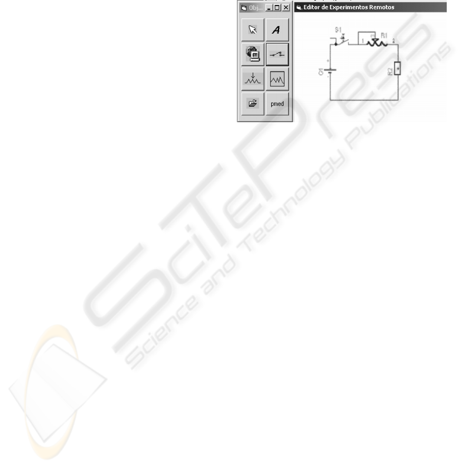
Experiment Editor - This application is
composed of two main windows: the toolbar,
on which the user selects the various objects
available; and the working area in which
objects are inserted and edited (figure 2).
Figure 2: Experiment Editor.
Objects are divided in two groups: hardware
objects, which are the electronic components that
take part on the circuit, and auxiliary objects such as
label, hyperlink and background image.
When an object is inserted in the working area, it
can be positioned and its properties can be modified
by clicking the right mouse button. For instance, the
digital potentiometer has properties as resistance
value, number of steps and identification on the
experiment board. Such data about the potentiometer
and also about the other objects are stored in an
XML (Extensible Markup Language) file. This file
format, universally accepted for information
exchange among heterogeneous systems, favors
integration among the distinct applications and
makes development easier, as this kind of file is
accessible to most present programming tools such
as Java and C/C++.
Remote Experiment Client - When this
application is started from the Web browser, it
establishes a socket connection and loads the
XML file with the object definitions
previously defined in the Experiment Editor.
Next, the properties of each object such as its
position on the screen, image, functionalities
and values are configured and the application
is enabled to receive the action of the remote
user. For instance, when a switch is clicked it
changes graphically from state open to closed
or vice-versa and generates an event that
captures the user action by opening a socket
WEBIST 2007 - International Conference on Web Information Systems and Technologies
406
connection that sends to the Experiment
Server a set of instructions with the executed
action.
Experiment Server - This application is
responsible for the communication between
the Remote Experiment Client and the Control
Board. The Experiment Server awaits a socket
connection. When this connection is
established, it captures the data and decodes
them; if they are valid, it sends them to the
USB port to which the Control Board is
connected.
GPIB Server - The communication between the
PC computer and an instrument endowed with
GPIB resources takes place through an
interface in the computer; as concerns
software, it happens by sending commands
and receiving data and status information. The
most common oscilloscope functions were
implemented and made available to users
through a graphical interface that seeks to
represent a real instrument with its buttons and
graphic screens. For the remote user to be able
to access this oscilloscope, sending commands
and receiving data, a module was
implemented which establishes a socket
connection with the GPIB Client.
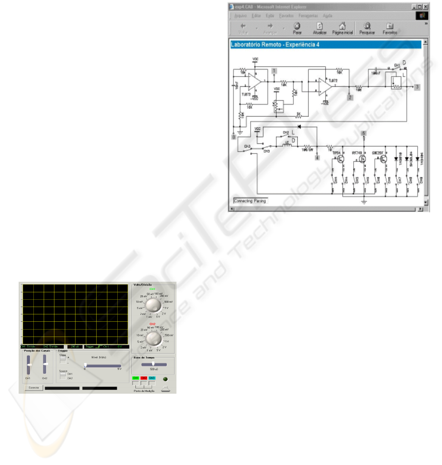
GPIB Client - Accessible from a Web browser,
it shows a graphical interface (figure 3) which
represents the real oscilloscope. A socket
connection allows control commands to be
sent to the GPIB Server and received data to
be seen on the graphic screen.
Figure 3: GPIB Client.
7 TEST AND EVALUATION OF
REMOTE LABORATORY
In order to evaluate the system, experiments
performed on the conventional laboratory of
Industrial Electronics in the undergraduate course of
the Faculty of Electrical Engineering - Unicamp,
were used. Experiment 4 of that course was wholly
implemented on the Experiment Editor. The
activities in this experiment involve turning switches
on and off, acting upon digital potentiometers and
making measurements with the oscilloscope in order
to analyze signals. The user interface is composed of
the experiment’s circuit diagram that can be seen in
figure 4.
Figure 4: Remote Client Experiment.
The switches and the potentiometers of the real
experiment are represented in the electronic circuit
diagram, and when clicked, work as if the student
were acting directly upon the conventional
experiment, i.e., the components would be
physically activated, i.e. switches will be turned on
or off and potentiometers would have their value on
the Experiment Board altered. For each user action a
visible output is presented, thus providing a faithful
representation of the state of the circuit that is being
experimented. Figure 5 shows the details of a
selection switch in the OFF position. When the
picture is clicked, a command will be sent which
shall close the switch on the circuit controlled by the
Control Board.
ARCHITECTURE FOR A REMOTE ACCESS LABORATORY WITH APPLICATION TO ELECTRONICS
ENGINEERING TEACHING
407
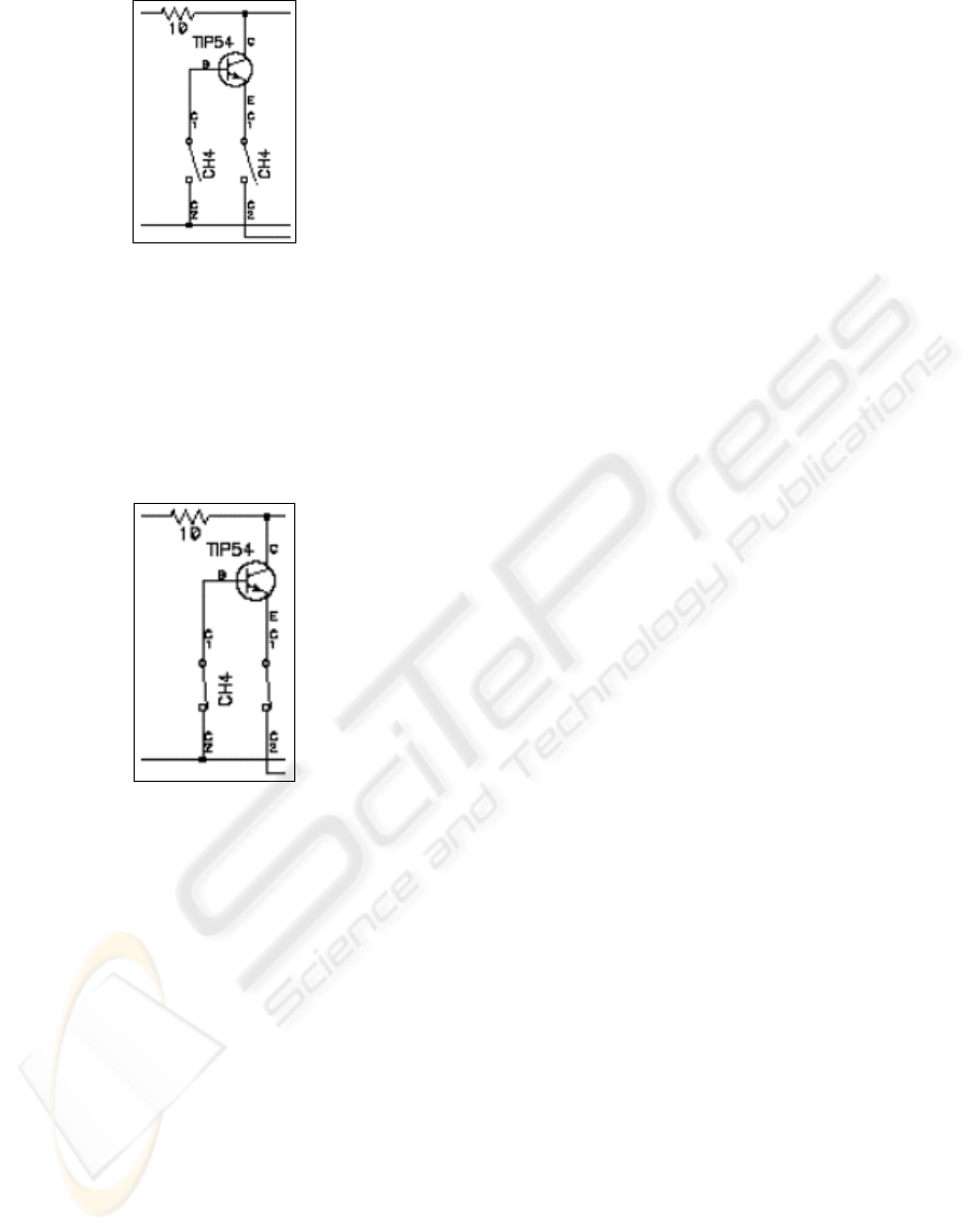
Figure 5: A detail of the graphical interface.
Employing the Experiment Client system, the user
then modifies the switch image (figure 6) in such a
way that it represents the closed switch condition,
and sends a command to the Experiment Server,
which passes it to the Control Board; this last one,
after decoding, acts upon the Electronic Block
switch on the Experiment Board.
Figure 6: Result of an action on a component of the
graphical interface.
8 FINAL REMARKS
In this article we presented the implementation of an
architecture for constructing a complete system for
remotely performing engineering experiments,
together with its initial evaluation. With this remote
laboratory architecture we plan to make available to
students experiments that may be accessed full time,
matching more easily the students’ availability of
time and being capable of serving a relatively larger
number of users.
During the elaboration of the experiments, the
Experiment Editor and the modular character of the
Electronic Blocks made it possible to implement and
modify experiments very quickly.
For this experiment we used a PC with a Celeron
800 MHz processor and 256 MB RAM running
Windows 2000. To this computer we connected the
Control Board running the Control Board Server
application. The oscilloscope, an HP 54403 model,
was connected to a Pentium 233 MHz with 128 MB
RAM and a National Instruments GPIB board,
running the GPIB Server. Both computers were
connected to the Internet.
A first evaluation of the remote laboratory
according to the parameters initially proposed
revealed the functionality, reliability and easy of use
of the distinct technologies integrating this system.
REFERENCES
Aulanet, 2003. Aulanet. Available from:
http://asgard.les.inf.puc-rio.br/aulanet/. [Accessed 25
January 2004].
Casini M., Prattichizzo D. e Vicino A., 2002. Automatic
Control Telelab: un Laboratorio Remoto per E-
learning. Available from:
http://www.dii.unisi.it/~control/act/reports/act_c1.pdf .
[Accessed 3 May 2005].
D'Abreu V. V. J. , Chella M. T., 2003. Ambiente de
Telerobótica em EaD. In: XIII Simpósio Brasileiro de
Informática na Educação - SBC2003, Campinas SP
Htsoft, 2004. PICC. Available from:
http://www.htsoft.com/. [Accessed 5 July 2005].
Hua, J. e Ganz, A.,2003. A new model for remote
laboratory education based on next generation
interactive technologies, Available from:
http://researchers.conferencexp.net/Lists/Research%20
Papers2/Attachments/5/aseeivlab.pdf. [Accessed 25
October 2004].
Microsoft, 2005. Visual Studio. Available from:
http://www.microsoft.com/. [Accessed 3 May 2005].
National, 2001. Labview. Available from:
http://www.ni.com/. [Accessed 10 January 2004].
Silva M., 2000. Sala de Aula Interativa. Quarter Ed. Rio
de Janeiro.
Schafer, T., Seigneur, J. M. e Donelly, A., 2002. PEARL:
A Generic Architecture for Live Experiments in a
Remote Lab. Available from:
http://iet.open.ac.uk/pearl/publications/icsee03.pdf,
[Accessed 15 October 2003].
Shen H., Xu Z., Dalager B., Kristiansen V., Strøm Ø.,
Shur M. S., Fjeldly T. A ., Lü J. e Ytterdal T., 1999.
Conducting Laboratory Experiments over the Internet,
IEEE Transactions on Education, vol. 42, n. 3, p. 180-
185.
Teleduc (2003) Teleduc. Available from:
http://teleduc.nied.unicamp.br/~teleduc/. [Accessed 28
January 2004].
WEBIST 2007 - International Conference on Web Information Systems and Technologies
408
