
REQUIREMENTS DEFINITIONS OF REAL-TIME SYSTEM
USING THE BEHAVIORAL PATTERNS ANALYSIS (BPA)
APPROACH
The Elevator Control System
Assem El-Ansary
CEO, Emergent Technologies USA, Inc., Principal Consultant, Keane Federal Systems
Keywords: Analysis, modeling approach, software modeling, event-oriented, behavioral pattern, use cases.
Abstract: This paper presents a new event-oriented Behavioral Pattern Analysis (BPA) modeling approach. In BPA,
events are considered the primary objects of the world model. Events are more effective alternatives to use
cases in modeling and understanding the functional requirements. The Event defined in BPA is a real-life
conceptual entity that is unrelated to any implementation. The BPA Behavioral Patterns are temporally
ordered according to the sequence of the real world events. The major contributions of this research are:
The Behavioral Pattern Analysis (BPA) modeling approach. Validation of the hypothesis that the
Behavioral Pattern Analysis (BPA) modeling approach is a more effective alternative to Use Case Analysis
(UCA) in modeling the functional requirements of Human-Machine Safety-Critical Real-time Systems.
1 INTRODUCTION
Experience reports problems with Use Cases such as
(Graham, 1995):
1. The lack of a Use Case formal specification
2. The lack of a notion of atomicity
3. The absence of the notion of triggering
events and business goals in determining use
cases
4. There is a problem with the phrase use case
itself.
A major problem in the use case approach is its
tendency to focus on the solution rather than the
problem (Jackson,1995).
The concluding statement of the “Question Time!
About Use Cases” Panel of the (Oopsla, 1998)
Conference by Ian Graham (Oopsola, 1998) was
“There is a need for another modeling approach with
a sound theoretical basis and a precise definition.”
This need is what this research problem area is
about.In addition to the problems with the use cases
(Oopsola, 1998) (Jackson, 1995) that were described
briefly above, several additional problems were
identified during this research (El-Sansery 2002, El-
Sansery, 2005). The following is a discussion of
these problems:
¾ The types of interactions are: interactions
among users, interactions between users and the
system, and interactions among the different
components of the system. Yet, use cases
describe only the users’ interaction with the
system. This is just one type of interaction.
¾ Because use cases’ description are used to
identify the objects, if use cases do not describe
all of the interactions, the resulting object
(class) model may be incomplete.
¾ As a result of this class model
incompleteness there will then be an incomplete
description of the interactions, and so the
sequence diagram may be incomplete.
¾ Using natural language in use cases
description, with the absence of any semantic
structure such as alternation or repetition,
increases the risks of ambiguity,
incompleteness, and inconsistency.
In conclusion, if the analyst misinterpreted or
neglected some structural or behavioral aspects, the
resulting conceptual model will not be a good
representation or understanding of the real world.
The resulting software solution system built from
the model may not demonstrate the correct behavior
or may ungracefully terminate. The end result might
be the loss of opportunities in using business
371
El-Ansary A. (2007).
REQUIREMENTS DEFINITIONS OF REAL-TIME SYSTEM USING THE BEHAVIORAL PATTERNS ANALYSIS (BPA) APPROACH - The Elevator
Control System.
In Proceedings of the Second International Conference on Software and Data Technologies - SE, pages 371-377
DOI: 10.5220/0001323603710377
Copyright
c
SciTePress

systems, serious damages in embedded systems, or
the loss of lives in using a safety-critical system.
This paper reports on Behavioral Pattern Analysis
(BPA), which is a more effective alternative to use
cases in modeling and understanding the functional
requirements (El-Lansary, 2002) BPA is an event-
oriented modeling approach in which events are
considered the primary objects of the world model.
While the term Event is used in UML, and in almost
all of the other modeling approaches, to mean an
occurrence of stimulus that can trigger a state
transition, the Event defined in BPA is a real-life
conceptual entity that is unrelated to any
implementation. In the BPA modeling approach, the
BPA Behavioral Pattern, which is the template that
one uses to model and describe an event, takes the
place of the Use Case in the UML Use Case View.
The BPA Behavioral Patterns are temporally
ordered according to the sequence of the real world
events.
2 ILLUSTRATING BPA
THROUGH THE ELEVATOR
CONTROL SYSTEM (ELCS)
The main function of the ELCS (Yourdon, 1996) is
to control group of elevators in a building. The
following describe the operation cycle:
¾ If someone summons an elevator by
pushing the down button on a floor. The next
elevator that reaches this floor traveling down
should stop at that floor. On the other hand, if
an elevator has no passengers (no outstanding
destination requests). It should park at the last
floor it visited until it is called again.
¾ An elevator that is filled to capacity,
should not respond to a new summon request.
There is an overweight sensor for each elevator.
¾ The interior of each elevator is furnished
with a panel consisting of an array of 40
buttons, one button for each floor, marked with
the floor number. These floor buttons can be
illuminated by signals sent from the computer to
the panel when a passenger presses a
destination button not already lit. An interrupt
for this elevator is sent to the computer. When
the computer receives one of these interrupts, its
program can read the appropriate memory
mapped to each elevator and each button.
¾ There is a floor sensor switch for each
floor for each elevator shaft. When an elevator
is within eight inches of a floor, a wheel on the
elevator closes the switch for that floor and
sends an interrupt to the computer. When the
computer receives one of these interrupts, its
program can read the appropriate mapped
memory that contains the floor number
corresponding to the floor sensor switch that
caused the interrupt.
¾ The interior of each elevator is furnished
with a panel containing one illuminate indicator
for each floor number.
¾ Each floor of the building is furnished
with a panel containing summon buttons. Each
floor except the ground floor (floor one) and the
top floor (floor forty) is furnished with a panel
containing two summon buttons, one marked
UP and one marked DOWN. The scheduler
decides which elevator should respond to a
summon request. When the computer receives
one of these two interrupts, its program can read
the appropriate memory mapped to the floor
number corresponding to the summon button
that caused the interrupt.
¾ There is a memory mapped control for
each elevator motor. Bit 0 commands the
elevator to go up, bit 1 commands the elevator
to go down, and the two bits commands the
motor to stop at the floor whose sensor switch is
closed.
¾ The elevator manufacturer uses
conventional switches, relays, and safety
interlocks for controlling the elevator doors so
that the computer manufacturer can certify the
safety of the elevator without regard to the
computer controller.
¾ Each elevator’s destination panel contains
a stop button which does not go to the
computer. Its sole purpose is to hold an elevator
at the floor with its doors open when the
elevator is currently stopped at a floor.
3 RESEARCH THESIS
The specific thesis is that the proposed Behavioral
Pattern Analysis (BPA) approach is more effective
than the Use Case Analysis (UCA) approach at
modeling the functional requirements of Interactive
Safety-Critical Real-time Systems. To validate that
the BPA approach is more effective than the Use
Case approach, sixteen Subject Matter Experts were
given two case studies that are modeled using the
two approaches and were asked to evaluate the
ICSOFT 2007 - International Conference on Software and Data Technologies
372

models using the Safety, Repeatability,
Unambiguity, Completeness, Consistency,
Modifiability, and Traceability as the effectiveness
criteria.
The following subsection presents a summary of
the research approach.
4 THE BPA REQUIREMENTS
DEVELOPMENT PROCEDURE
The following is an outline of the BPA functional
requirements development procedure:
1 Identify the problem at the highest level of
abstraction (e.g. The Mission Statement
and Operating Requirements).
2 Identify the scope of the requirements
(problem) from the Originating
Requirements.
3 Analyze the Originating Requirements to
identify the Critical Constraints (e.g.
Safety) and/or the Utility Requirements.
4 Decompose the scoped problem (from step
2) into Main Events based on the Mission
and Operating Requirements (Step 1).
5 Using the identified Main Events, draw the
High Level Event Hierarchy Diagram
(Figure 3).
6 Decompose these identified Main Events
into smaller and simpler events represented
as Episodes (Composite Events) with clear
boundaries
1
. An Episode Boundary at this
stage may be marked with Location / Loci
of Control and Effect. Add additional levels
to the Event Hierarchy Diagram (Event
Hierarchy Sub-Diagrams). For complex
problems, it is often helpful to extract these
sub-diagrams and analyze them. Detailed
level event hierarchy diagrams are drawn as
necessary.
¾ The Event Decomposition Heuristics at
this stage is ‘One Agent and One
Location’.
7 For each identified main event (from step
4) draw an Event Thread Diagram (Fig. 4).
¾ Starting with the Main Events, as
initial composite events, recursively
decompose the composite events into
Basic Events
¾ The Event Decomposition Heuristics at
this stage is ‘One Agent, One
Location, One Motion Direction, and
One Time Interval’.
¾ Group Basic Events by their Location /
Loci of Control and Effect. Draw a
frame box around these Basic Events
8 Refine and transform the above Basic
Events into their corresponding BPA
Behavioral Patterns (Figure 5 represents a
Behavioral Pattern sample).
9 Using the Event Thread Diagrams from
step 8, draw the Temporal/Causal
Constraint Diagrams by adding the
temporal constraints alongside the
associations and identifying the
enable/causal relationships in each
corresponding Event Thread Diagram
(Figure 8).
10 Using the Critical Constraints (e.g. Safety),
identify the critical events, identify all
possible ways of each critical event’s
failure, and draw the Critical Event
Analysis Diagram (Figure 9).
11 Using the BPA Event Patterns and the
Critical Event Analysis Diagrams, identify
any missing requirements that are necessary
to satisfy the critical constraints. If these
missing requirements are not in the
Originating Requirements document,
develop a Derived Requirements document
and get users approval on this document.
12 Using the Missing Requirements (from step
11), refine the Event Hierarchy Diagram
(from step 6), the Thread Diagrams (from
step 7), and the Temporal Constraint
Diagram (from step 9) as necessary. Draw
additional Event Thread Diagrams for
identified critical events as necessary. The
figure (Figure 1) below illustrates the
iterative and incremental development
process that is used in the BPA approach.
13 Using the BPA Event Patterns (from step
8), identify the candidate Classes from the
Event Roles (Participants) and Instrument.
Draw the Class Diagram (figure10).
14 To illustrate the relationship between
Events and States, optionally, using the
BPA Behavioral Patterns, draw the
Event/State History Chart (Optional – not
shown) that includes the States before and
after each Event for each identified Class
whose instance is a participant in that
Event. This chart helps in developing the
state model during the design stage.
REQUIREMENTS DEFINITIONS OF REAL-TIME SYSTEM USING THE BEHAVIORAL PATTERNS ANALYSIS
(PBA) APPROACH
373
I-III IV-VII
VIIIIX-X
Originating
Requirements
Derived
Requirements
XI
XII
Begin Refinement
Start
Missing
Requirements
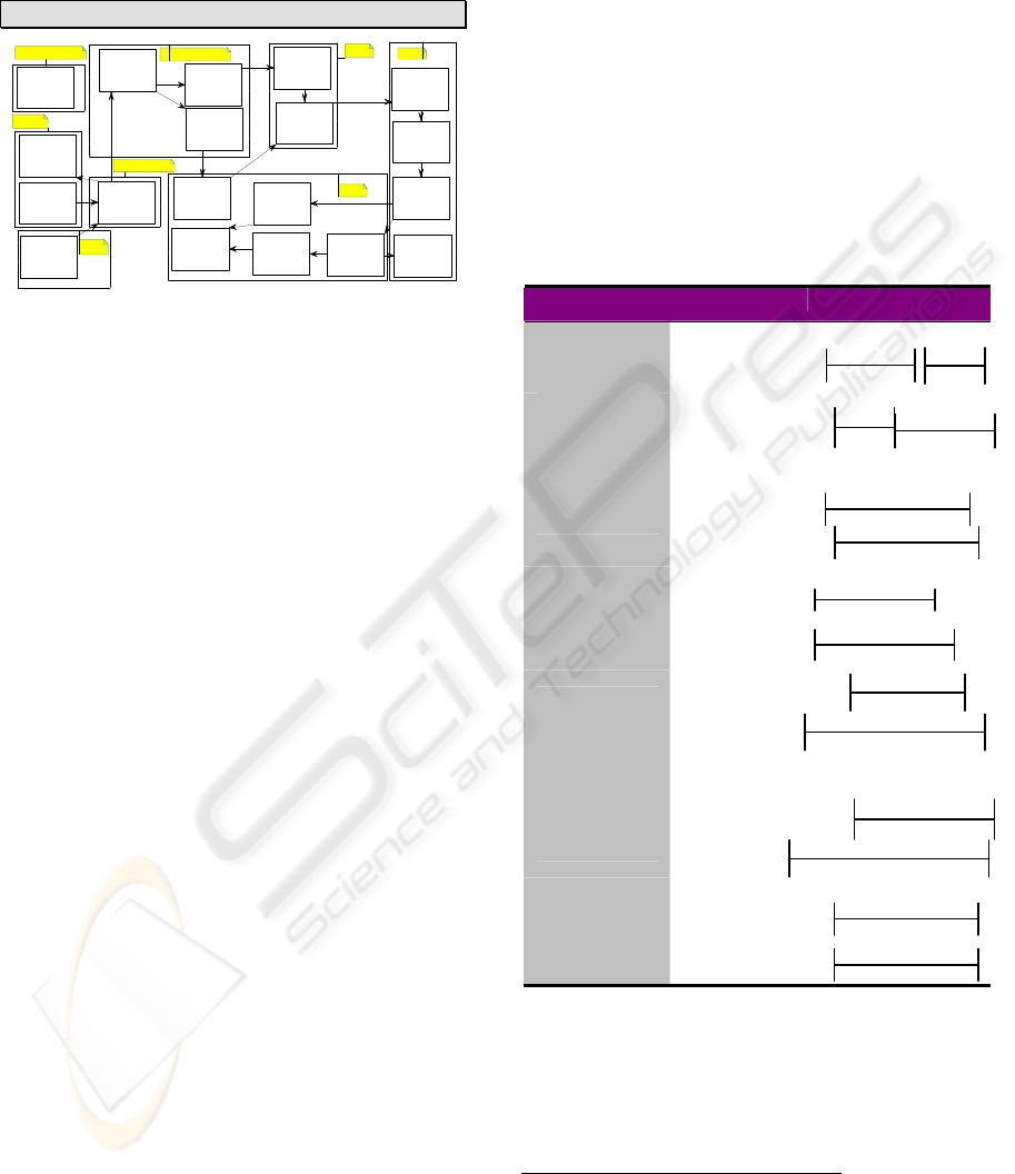
Figure 1: The BPA Modeling Process.
The above procedure illustrates the BPA functional
requirements development procedure Figure 2
depicts the flow of the modeling activities for the
BPA procedure.
Event
Hierarchy
Diagram
IV, V, VI
Event
Thread
Diagram
VII
Critical Event
Analysis
Diagram
X
BPA
Behavioral
Pattern
VIII
Class
Diagram
XIII
Event /
State History
Chart
XIV
Temporal/Causal
Constraints
Event Thread
Diagram
IX
Missing
Req’ts?
XI
No
Refine diagrams XII
Yes
I Mission
II Originating
Requirements
III Critical
Constraints
Figure 2: Requirements Development Procedure.
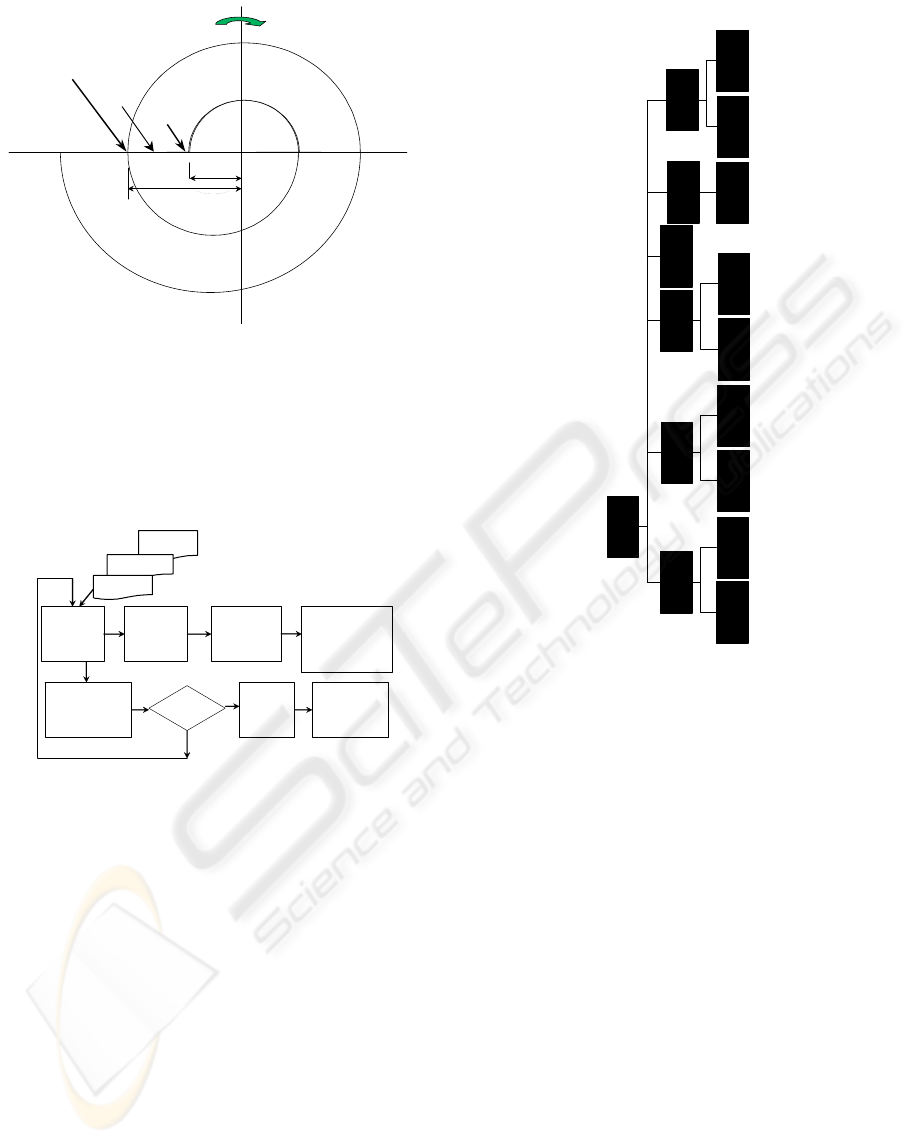
4.1 Event Hierarchy Diagram (EHD)
Because there are many levels of requirements
details analysts need techniques to structure the
excessive amount of requirements information that
surfaces. Event Hierarchy is used to model the
events at different levels of abstraction (event
decomposition). As per steps 4, 5, and 6 in the BPA
procedure, a general problem with decomposition is
when to stop the decomposition. To overcome this
problem, the decomposition heuristic used in an
Event Hierarchy Diagram (EHD) is one agent and
one location. Using this heuristic, the leaf events in
an Event Hierarchy are usually Simple Sequence
Events. In other words, a leaf event is usually a set
of Basic Events (atomic events) sequenced into
episode
1
. The episode is marked with a location
boundary. The following is the ELCS detailed Event
Hierarchy Diagram:
Figure 3: Event Hierarchy – Elevator Control.
Using the identified main events, the high level
EHD diagram (or the first level in a detailed EHD
diagram) is drawn. Each main event is then
decomposed further until one arrives at leaf events,
each of which has one location or one locus of effect
and control and one agent.
In order to model the sequence of events (and show
the location / loci of control and effect view, or the
temporal / causal constraints), one uses the event
thread diagrams as shown in the next subsections.
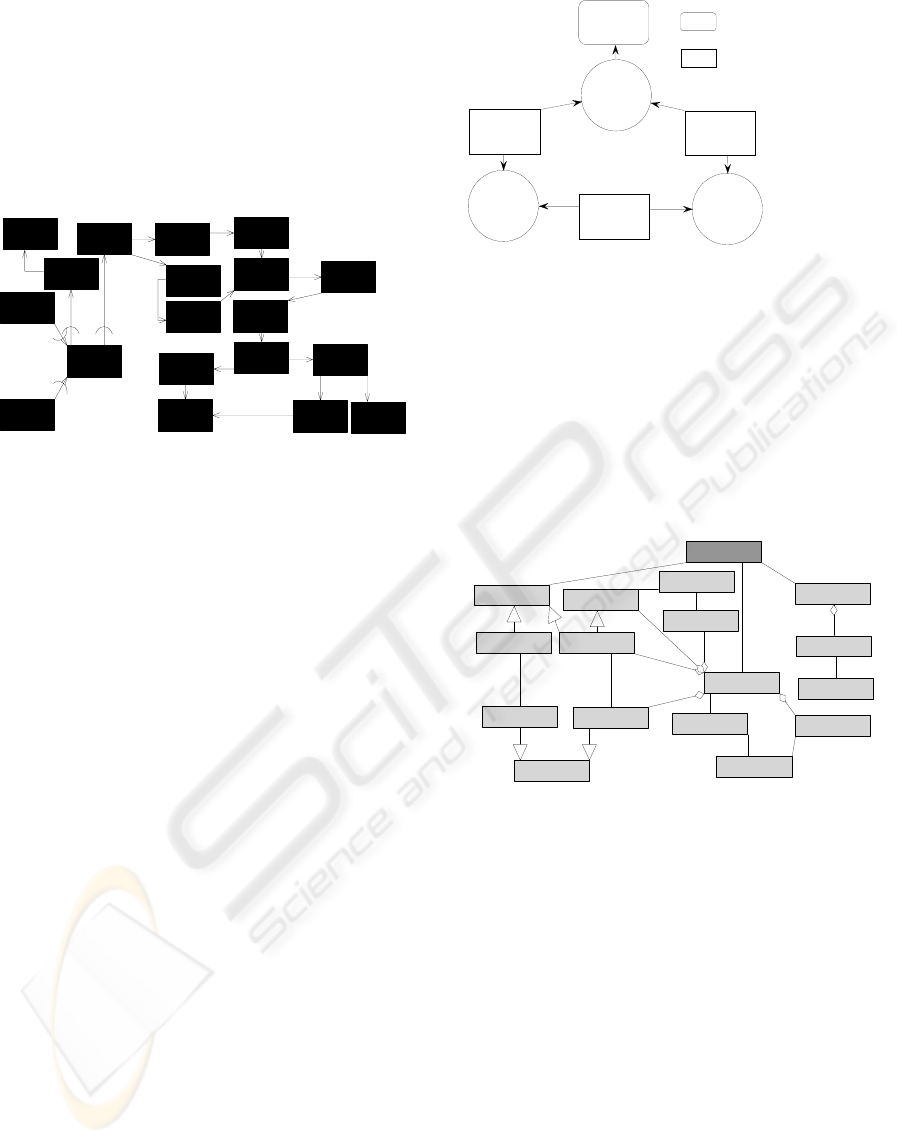
4.2 Event Thread Diagram (ETD)
In BPA, as per step 7, an Event Thread Diagram
(ETD) is drawn for each main event, and optionally
drawn for any other event, subordinate to main
event, depending on its complexity or its critical
nature.
A Basic Event is defined as an event that cannot be
decomposed into another set of events (atomic
event). The heuristic used in decomposing an event
into its basic events is one agent, one location, one
time interval, and one motion direction if the event
Elev ator Control
pressing
Summon Button
Pressing
Elevator Button
Traavelling Up
*
Trav ell ing Dow n
*
Calling Up
*
Calling Dow n
*
Approaching
Flo or
*
Stopping AT
Flo or
Opening Doors
*
Pressing Stop
Button
Hold i n g Do or s
Ope n
*
Calling Up
*
Calling Dow n
*
Reg is tering
Int er r upt
Operating Door
Rela y
*
ICSOFT 2007 - International Conference on Software and Data Technologies
374
involves any motion. The ETD, which one draws
for an event, shows the sequence of the basic events
of that event.
Event Thread Diagram: ‘Elevator Control’
pressing
Summon Button
Pressing
Elevator Button
Calling
Do w n
Calling Up
Traavelling
Up
Travelling
Dow n
Approaching
Flo or
Stopping A T
Flo or
Opening
Doo rs
Releas ing
Passengers
Clo sin g
Doors
Registering
Interrupt
Checking
Scheduler
Closing Floor
Sensor Sw itch
Pressing
Stop Button
Holdin g
Doors Open
Releasing
Stop Button
Disregard
Interrupt
Overw eight
Sensor On
Floor
Elevator Controller
Elevator
Flo or
Elevator
Elevator
Elevator Controller
Elevator Controller
Figure 4: Event Thread –Elevator Control System.
4.3 Behavioral Patterns
As explained earlier in step 8, the research goal is to
develop a requirements definition mechanism (BPA
Pattern) that describes the What, Who, How, When,
Where and Why.
BPA BEHAVIORAL PATTERN - EXAMPLE
Event (WHAT?) Elevator Control System
Actions
1. Pressing Summ Button 2. Pressing Elev Button
3. Calling UP 4. Calling Down
5. Approaching Floor 6. Stopping At Floor
Agent a: Elevator
¾ Initial State: Idle
¾ Final State: Moving Up/Down
Affected p: Passenger
¾ Initial State: At Floor
¾ State: Moving Up/Down
Modality (HOW?)
Instrument
i: Elevator Motor
Circumstances
Manner
m: Critical
Condition
c1: Idle c2:
Effect
f1: Moving Up/Down f1: Moving Up/Down
Date/Time (WHEN?)
t:
Place (WHERE?)
Location
l:Elevator
Path
Motion
m: Moving
Direction
d: Up/Down
Rationale (WHY?)
Goal g: Carrying Passengers Up/Down
Mental State bdi:
Caused-By e’: Elevator
End;
Figure 5: BPA Pattern–Elevator Control.
4.4 Introducing Time
The key intuitions motivating the introduction of
time are:
¾ Events take time. Yet, in most of the
Modeling approaches such as OMT and UML,
time is neglected in the event definition.
¾ Events may have temporal constraints.
BPA uses the time intervals’ relations that are
described in the Interval Algebra framework
(Allen, 1983) to model the temporal
relationships between events. Figure 6
illustrates these basic relations for arbitrary
events x and y.
REL SYM MEANING
x
before
y
b
x
meets
y
m
x
overlaps
y
o
x
starts
y
s
x
during
y
d
x
finishes
y
f
x
equals
y
eq
Figure 6: Time Interval Algebra–Temporal Relations.
4.5 Introducing Enable/Cause
Relationships
The introduction of the Enable
1
. Cause relationships
1
‘Enable’ is defined in the American Heritage Dictionary as: “.To
supply with the means, knowledge, or opportunity; make able: a hole
in the fence that enabled us to watch; techniques that enable surgeons
to open and repair the heart.”
x
x
y
x
y
x
y
x
y
x
y
x
y
y
REQUIREMENTS DEFINITIONS OF REAL-TIME SYSTEM USING THE BEHAVIORAL PATTERNS ANALYSIS
(PBA) APPROACH
375
between events will enable the analyst to do cause
effect analysis and reason about any possible failure
of the system.
In the Temporal Constraint Diagram, as described in
steps 9, and 10, the temporal relations, that are
displayed in Figure 7, are written alongside the
sequence relationships between the events to
represent the possible timing at which these events
can occur.
Approaching
Floor
Calling Dow n
Calling Up
Pressing
Elevator Button
Stopping AT
Floor
Traav elling Up
Travelling Dow n
pressing
Su mmon Bu t ton
Opening Doors
Closing Doors
Releasing
Pa s s e n g e r s
Pressing Stop
Button
Holding Doors
Open
Chec kin g
Scheduler
Regis ter ing
Int er r upt
Closing Floor
Sensor Sw itch
Releasing Stop
Button
Overw eight
Sensor On
Dis r e ga rd
Inter rupt
{b,o}
{b, m }
{ b,m}
{b,m }
{ b,o}
{b, m}
{ b,o }
{ b, m}
{ b, f}
{ b }
OR
{ b}
OR
{b }
{b,f, m}
{b, f, m}
{b}
{b, f }
OR
{b,m,f}
{ b }
OR
{b, f}
{m}
Figure 7: Temporal Constraint Diagram–Elevator Control.
4.6 Failure Issues
The ability to provide requirements specification for
safe behavior is very limited using the current
modeling approaches. Neither a safety analysis
(anterior analysis) nor accident analysis (posterior
analysis) can be achieved efficiently without event
analysis. As will be explained below, the BPA
modeling approach provides the Critical Event
Analysis as an efficient solution to this problem.
4.6.1 Critical Events Analysis
The Critical Event Analysis procedure includes the
following steps:
¾ Identify Critical Events
¾ For each critical event, identify all possible
ways in which it may fail
¾ Capture these possible failure modes using
the undesired event notation
¾ Study each undesired related state to find
out how to achieve protection against such
possible failure
The following diagram (Figure 8) illustrates the
critical event analysis in BPA as described in step
11:
Figure 8: Critical Analysis Diagram-Subscribing.
5 MISSING REQUIREMENTS
There were no missing requirements that required
generating a Derived Requirement Document.
6 ELCS CLASS DIAGRAM (STEP
12)
«user»
::Passanger
«business»
::Elevator Button
«business»
::Summon Button
«business»
::Sum m on Button Light
«business»
::Ele va t or But t o n L ight
«business»
::Floor
«business»
::Floor Sensor
«business»
::Elevator
«business»
::Eleva t or Door
«business»
::Elevator M o tor
«business»
::But t o n
«business»
::Light
«business»
::Stop Button
«business»
::Floor Sensor Switch
«business»
::Door Relay
«business»
::Elevator Control
«business»
::Control Register
*
1
*
1
*
1
*
1
*
1
*
1
*
1
*
1
*
1
*
1
*
1
*
1
*1
*
1
*
1
*
1
*
1
Is A
Is A
IsA
Is A
Is A
Figure 9: Class Diagram–ELCS.
7 EVALUATION OF THE
EFFECTIVENESS OF THE BPA
MODELING APPROACH AND
THE UCA MODELING
APPROACH
In this research, three real-life applications were
used to illustrate the effectiveness of the new BPA
modeling approach in handling safety-critical real-
time systems development:
1 The Therac-25 Medical Device System
([Leveson, 1996).
2 The Production Cell System (Lewerentz,
1995).
Elevator
A
ccident
Traavelling
U
Travelling
Dow
Opening
Doors
OR
A
N
A
N
Undesired
Event
(failure)
State
ICSOFT 2007 - International Conference on Software and Data Technologies
376

3 The Railroad Crossing System
(Heitemyer, 1996).
The UCA and the BPA modeling approaches were
used to define the requirements and model these
systems. The first application was used, as a proof of
concept, in a pilot case study. The last two
applications were distributed as part of the case
studies material to compare the UCA versus the
BPA modeling approaches using the pre-mentioned
effectiveness criteria.
8 WHY THIS WORK IS
IMPORTANT
8.1 Real-Time Systems
In most of the development modeling approaches
state diagrams are used to model the behavior. By
using state diagrams, one is focusing on an
individual object’s response to specific events rather
than objects interaction. Hence, objects interaction
must be reconstructed from the analysis of groups of
diagrams. Such a task is at least complex and error-
prone. However, in BPA, by describing the
requirements in terms of events, represented by the
behavioral patterns, this perceived problem is
reduced.
8.2 Multi-Agent Systems
There is a need for a multi-agent systems analysis
and design method that is powerful enough to model
interaction patterns involving autonomous agents.
BPA modeling approach can be used to model
multi-agent systems effectively.
8.3 Safety-Critical Systems
In these systems, analysts should perform a ‘Safety
Analysis’. Using BPA, one identifies and documents
the critical events during the requirements definition
stage.
GOD says (Koran) (Torah), “(…) Whoever rescues
a single life earns as much merit as though he had
rescued the entire world.” If the use of the BPA
Modeling approach may save one life, the
significance of this modeling approach is
immeasurable.
REFERENCES
Allen, J. F., Maintaining Knowledge about Temporal
Intervals, Communications of ACM, 26, 1983.
Bell, T. and Thayer, T., Software Requirements: are they
really a problem?, Second International Conference on
Software Engineering, 1976.
Booch, G.,Jacobson, I., and Rumbaugh, J., The Unified
Modeling Language User Guide, Addison Wesley,
Reading, Massachusetts, 1999.
Davidson, D., Essays on Actions and Events, Oxford
University Press, New York, 1980.
El-Ansary, Assem I., Behavioral Pattern Analysis:
Towards a New Representation of Systems
Requirements Based on Actions and Events, in
Proceedings of the 2002 ACM Symposium on Applied
Computing, ACM, New York, NY, 2002.
El-Ansary, Assem I., Behavioral Pattern Analysis:
Towards a New Representation of Systems
Requirements Based on Actions and Events, Doctoral
Thesis, George Mason University, 2005.
Graham, Ian, Migrating to Object Technology, Addison-
Wesley, Reading, Massachusetts, 1995.
Heitmeyer, Constance and Mandrioli, Dino, Formal
Methods for Real-Time Computing: An Overview, in
Formal Methods for Real-Time Computing, John
Wiley & Sons, Inc., NY, 1996.
IEEE and ANSI, ANSI/IEEE Std 830-1984, IEEE Guide
to Software Requirements Specification, in System
and Software Requirements Engineering, IEEE
Computer Society Press, Los Alamitos, CA, 1990.
Jackson, Michael, Software Requirements &
Specification, A Lexicon of Practice, Principles and
Prejudices, ACM Press, Reading, MA, 1995.
Jacobson, I., Christeron, M., and Overgaard, Object-
Oriented Software Engineering: A Use Case Driven
Approach, Addison-Wesley, Reading, MA, 1992.
Lewerentz, Claus, and Lindner, Thomas, Formal
Development of Reactive Systems, Springer-Verlag,
NY, 1995.
Fowler, Martin and Cockburn, Question Time! About Use
Cases, OOPSLA’98 Proceedings, ACM Press, New
York, NY, 1998.
Edward Yourdon and Carl Argila, Case Studies in Object
Oriented Analysis & Design, Prentice Hall, Upper
Saddle River, NJ, 1998.
REQUIREMENTS DEFINITIONS OF REAL-TIME SYSTEM USING THE BEHAVIORAL PATTERNS ANALYSIS
(PBA) APPROACH
377
