
ENTERPRISE ONTOLOGY AND FEATURE MODEL INTEGRATION
Approach and Experiences from an Industrial Case
Kurt Sandkuhl, Christer Th
¨
orn and Wolfram Webers
J
¨
onk
¨
oping University, School of Engineering, P.O. Box 1026, 55111 J
¨
onk
¨
oping, Sweden
Keywords:
Ontology Engineering, Feature Model, Software Engineering, Knowledge Engineering, Conceptual Integra-
tion.
Abstract:
Based on an industrial application case from automotive industries, this paper discusses integration of an
existing feature model into an existing enterprise ontology. Integration is discussed on conceptual and on
implementation level. The main conclusion of the work is that while integrating enterprise ontologies and
feature models is quite straightforward on a conceptual level, it causes various challenges when implementing
the integration with Prot
´
eg
´
e. As ontologies have a clearly richer descriptive power than feature models, the
mapping on a notation level poses no serious technical problems. The main difference of the implementation
approaches presented is where to actually place a feature. The first approach follows the information modeling
tradition by considering features as model entities with a certain meta-model. The second approach integrates
all features and relations directly on the concept level, i.e. features are considered independent concepts.
1 INTRODUCTION
During the last years numerous approaches of us-
ing ontologies in software engineering were devel-
oped and published resulting in a sophisticated body
of work on potentials and limits of this technology.
Examples include knowledge sharing in software de-
velopment (Shull et al., 2004), domain ontologies in
software engineering (Musen, 1998) or ontolgies in
information systems (Guarino, 1998).
The contribution of this paper is integrating on-
tologies with another well-researched technique: fea-
ture models (FM). Driven by an industrial application
case and inspired by earlier work on feature models
and ontologies, different perspectives on integrating
feature model and ontology are presented and dis-
cussed. More specific, the focus of the work is on in-
tegrating a feature model into an enterprise ontology
(EO). The purpose in the case under consideration is
to support efficient development of software-intensive
systems (see section 2). As feature models also sup-
port this general purpose, the integration is not only
of academic interest but also meets industrial needs.
The following section will introduce the industrial
case motivating the integration of feature models and
enterprise ontologies. Section 3 will introduce dif-
ferent perspectives on integrating feature models into
enterprise ontologies. Section 4 is dedicated to dis-
cussing the developed approaches, both in compar-
ison to earlier work in the field and regarding their
potentials and limits. Section 5 summarizes the work
and draws conclusions.
2 APPLICATION CASE
In this section, development of an enterprise ontol-
ogy (2.1) and a feature model (2.2) for a supplier of
software-intensive systems for the worldwide auto-
motive industry is described and the need for integrat-
ing both is motivated (2.3).
2.1 Enterprise Ontology Construction
and Use
The application background for this paper is a
Swedish automotive supplier of software-intensive
264
Sandkuhl K., Thörn C. and Webers W. (2007).
ENTERPRISE ONTOLOGY AND FEATURE MODEL INTEGRATION - Approach and Experiences from an Industrial Case.
In Proceedings of the Second International Conference on Software and Data Technologies - PL/DPS/KE/WsMUSE, pages 264-269
DOI: 10.5220/0001327102640269
Copyright
c
SciTePress
systems. The primary application scenario for the
ontology developed is integration of different kinds
of structures reflecting the artefacts produced during
the software development process and their interre-
lations. On the one hand, model hierarchies have
to be captured, indicated and implemented on differ-
ent modelling levels (system, product, software, hard-
ware, etc.). On the other hand, term networks and
taxonomies have to be considered as equally impor-
tant. These networks represent organizational struc-
tures, product structures or taxonomies originating
from customers that are closely related to artefacts.
Explicit denotation of these relationships are consid-
ered beneficial for identification of reuse potential of
components or artefacts.
The intended use of the enterprise ontology devel-
oped is to capture correspondences between the dif-
ferent artefacts, express overall constraints and pro-
vide navigation support between the artefacts for dif-
ferent stakeholders.
The ontology development process applied is an
enhanced version of the METHONTOLOGY pro-
cess (Fern
´
andez et al., 1997) as described in (
¨
Ohgren
and Sandkuhl, 2005). Most important knowledge
sources were (1) a description of the suppliers internal
software development process, (2) documentation of
two example cases for requirements handling, and (3)
interviews and working sessions with members of the
software development department. The resulting on-
tology consisted of 379 concepts and with an average
depth of inheritance of 3.5.
Among the many ontology definitions available,
we will use the following definition, which is based
on (Maedche, 2003): An ontology structure is a 5-
tuple O := {C, R, H
C
, rel, A
O
}, consisting of
• two disjoint sets C and R whose elements are
called concepts and relations respectively.
• a concept hierarchy H
C
: H
C
is a directed relation
H
C
⊆ C ×C which is called concept hierarchy or
taxonomy. H(C
1
, C
2
) means that C
1
is a subcon-
cept of C
2
.
• a function rel : R → C ×C, that relates concepts
non-hierarchically (note that this also includes at-
tributes). For rel(R) = (C
1
, C
2
) one may also write
R(C
1
, C
2
).
• a set of ontology axioms A
O
, expressed in an ap-
propriate logical language.
2.2 Feature Model Development and
Use
The secondary application scenario is the representa-
tion of commonalities and variability of products de-
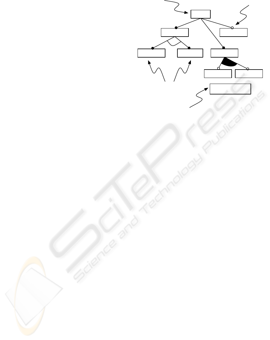
Car
Gear box Air condition
EngineManual Automatic
Gasoline Electric
"Automatic" requires
"Gasoline"
Alternative
features
Constraint
Root feature
Optional feature
Figure 1: Some elements of a feature model (Kang et al.,
1990).
veloped in our use case. On the one hand the cus-
tomers demands for the product need to be captured,
indicated in functional and non-functional require-
ments specifications. On the other hand the exist-
ing artefacts relating to these requirements need to be
considered in terms of hierachical structures (system,
module, function, etc.) providing potential solutions.
The intension is to be able to configure such prod-
ucts very early in the development process with re-
spect to several constraints. Such a constraint might
be stakeholder oriented, like the different regulations
found in different countries the product will appear.
Others might directly derive from the product realiza-
tion, like competing, mutial exclusive solutions to a
single problem.
In order to support reuse of artefacts, the common-
alities and variations in the existing requirement and
product specifications had to be described. It was de-
cided to use feature models (FM), like they are intro-
duced by Kang et al (Kang et al., 1990),(Kang et al.,
2002) and Czarnecki et al(Czarnecki and Eisenecker,
2000). Feature models describe the problem domain
in terms of visible product features. These features
are generally visualised with the help of feature trees.
An example for such a feature tree is shown in Fig-
ure 1.
Additionally, the process applied based on the
concepts introduced in CONSUL (Beuche et al.,
2004). This method adds the solution domain by us-
ing family models existing solutions and relates them
to features. Such solutions can be represented on ar-
bitrary levels of abstraction, e.g. from architectural
descriptions down to the source code level. Generally,
ENTERPRISE ONTOLOGY AND FEATURE MODEL INTEGRATION - Approach and Experiences from an Industrial
Case
265
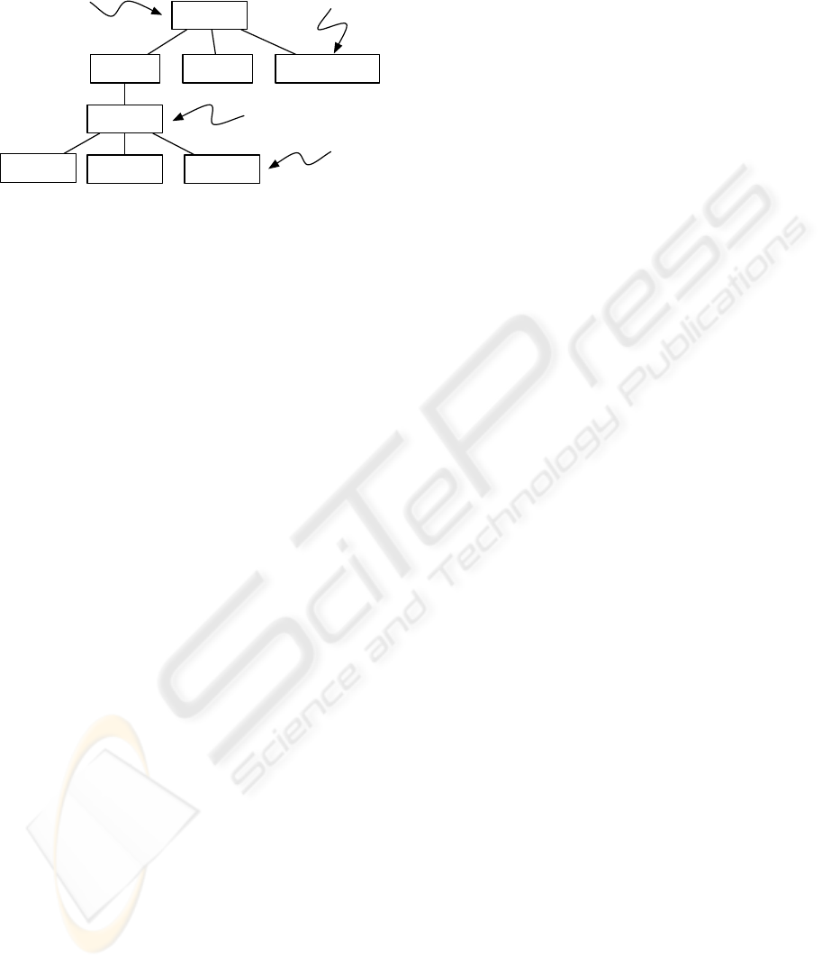
family models represent solutions on a logical level.
An excerpt of such a model is shown in Figure 2.
Airbag
Hardware
Sensors Actuators Communication
Passenger
Sensor
OC3
SBE PODS
Family
Component
Part
Solution
Figure 2: Excerpt of a family model.
The application case developed a feature model
and two family models, based on the product spec-
ifications of two examples. Although the resulting
feature model was rather small (it contains only 36
elements and an average depth of 4), it represents sev-
eral hundred variants, which exist in real world (out of
9.8 million variations theoretically possible when not
taking the constraints into account).
Before discussing the integration of these feature
models into the enterprise ontology, the constituents
of a feature model have to be defined more precisely.
We define a feature model as a tuple FM :=
{F, R, man, opt, alt, req, excl}, consisting of
• two disjoint sets F and R whose elements are
called feature and relations respectively.
• a function man : R → F ×F that relates mandatory
features. With man(R) = (F
1
, F
2
) we define F
2
as
a mandatory sub-feature of F
1
.
• a function opt : R → F × F that relates optional
features. With opt(R) = (F
1
, F
2
) we define F
2
as a
optional sub-feature of F
1
.
• a function alt : R → F × F that relates alternative
features. With alt(R) = (F
1
, F
2
) we define F
2
as a
alternative sub-feature of F
1
.
• a function req : R → F × F that relates required
features. With req(R) = (F
1
, F
2
) we define F
2
as a
required sub-feature for F
1
.
• a function excl : R → F × F that relates mutually
exclusive features. With excl(R) = (F
1
, F
2
) we de-
fine F
2
is mutually exclusive to F
1
.
This definition follows the intention introduced
with FODA (Kang et al., 1990). The definition of
family models is not included here, as it is not re-
quired for the following discussions.
2.3 Why Integrate EO and FM?
During the runtime of the project with the automo-
tive supplier, new application scenarios for the EO
described in 2.1 emerged: artefact management and
support of requirement analysis.
In artefact management, the main intention is to
use the EO as a representation for additional meta-
data characterising the content of artefacts related
to the software process, like design descriptions, re-
quirement specifications or test instructions. Com-
mon practice in repositories or document manage-
ment systems is to use a set of attributes and key-
words describing an artefact. By adding relevant sub-
sets of the EO, an artefacts’ meta-data can be enriched
for supporting searching and retrieval (see also (Billig
and Sandkuhl, 2002) for a similar approach).
In order to support requirements analysis, the ob-
jective is to calculate a similarity measure between
a customer requirement specification (CRS) and the
artefacts available at the automotive supplier. The ra-
tionale behind this idea is that a high degree of sim-
ilarity between CRS and artefacts could indicate that
these artefacts contribute to deliver the required func-
tions. In a first step, an ontology for the CRS will be
created by using an automatic ontology construction
approach (
¨
Ohgren and Sandkuhl, 2005). This CRS
ontology will afterwards be mapped on the EO, al-
lowing for identification of artefacts with a meta-data
sub-set related to the CRS ontology.
As an CRS to a large extent specifies the features
to be delivered, we consider an enrichment of the EO
with information about features, their dependencies
and characteristics as precondition. Without the fea-
tures being included in the EO, it obviously would not
be possible
• to map features included in the CRS ontology
onto the EO ontology
• to use features in the EO as additional meta-data
in artefact management, i.e. characterising arte-
facts by defining an ontology sub-set which con-
tains the features the artefact is addressing.
This calls for the integration of FM and EO.
3 INTEGRATION OF FEATURE
MODEL INTO ENTERPRISE
ONTOLOGY
When discussing approaches to integrate FM and EO,
we have to distinguish between different development
phases of an ontology:
• The conceptual stage where the main elements,
structures, relations and constraints of an ontol-
ogy are identified based on the knowledge of the
domain experts and other knowledge sources.
ICSOFT 2007 - International Conference on Software and Data Technologies
266

• The implementation stage coding the result from
the conceptual stage in appropriate representation
with a suitable tool.
• The application stage concerning the pruning and
optimisation of the implementation for the appli-
cation purpose.
In the application case under consideration, concep-
tual stage and implementation stage were performed
and resulted in a number of findings regarding fea-
ture model and enterprise ontology integration. These
findings are presented in the next sections.
3.1 Conceptual Phase
From a conceptual perspective, the task at hand is to
represent the FM elements introduced in 2.2 with the
ontology notation presented in 2.1 while preserving
the conceptualisation inherent to the feature model.
As ontologies have a clearly richer descriptive
power than feature models (Czarnecki et al., 2006),
the mapping on a notation level does not cause serious
technical problems. The approach proposed in this
paper is to preserve the hierarchy between mandatory
features in a FM by mapping a feature sub-feature pat-
tern to a concept hierarchy in the EO. The other rela-
tionships between features in the FM, i.e. optional, al-
ternative, required and mutual-exclusive patterns be-
tween features, are represented in the EO by creat-
ing a concept hierarchy and the respective relation-
ship types in the ontology. Table 1 summarizes the
proposed mapping.
Table 1: FM to EM mapping.
Feature
model
Enterprise
ontology
Remark
F C Features are repre-
sented as concepts
man(F
1
, F
2
) H(C
1
, C
2
) Feature hierarchy is
represented as con-
cept hierarchy
opt(F
1
, F
2
) H(C
1
, C
2
)
opt(C
1
, C
2
)
alt(F
1
, F
2
) H(C
1
, C
2
)
alt(C
1
, C
2
)
req(F
1
, F
2
) H(C
1
, C
2
)
req(C
1
, C
2
)
excl(F
1
, F
2
) H(C
1
, C
2
)
excl(C
1
, C
2
)
Other feature rela-
tions are included in
the feature hierarchy
and additionally rep-
resented as the same
relationship type in
EO
An alternative approach for handling the optional,
alternative, required and excludes relationships would
be to express the relationship type by using a spe-
cific attribute of the concepts representing the fea-
tures. Technically, this would require a relationship
“feature
type” and concepts representing these fea-
ture types. This approach was not selected as it would
establish the feature types as concepts equivalent to
features, which was not our intention.
Another issue is where in the EO to place the root
for the FM. This should be decided in close collabo-
ration with the domain experts from the enterprise, as
the EO has to reflect the conceptualisation shared in
the enterprise.
3.2 Implementation Phase
Very early in the project, it was decided to use
Prot
´
eg
´
e (Prot
´
eg
´
e, 2007) as our framework to imple-
ment the enterprise ontology as well as integrating
the feature model. Prot
´
eg
´
e offers an own modeling
language, which consists among others of classes,
class hierarchies and slots. The modeling language
is defined on the same level as the ontology defined
by using the language. I.e. taxonomies in a con-
crete ontology are classes with “instanceOf” relations
to the language concepts. Hierarchies are built on
“isA” relationships among these classes. Own rela-
tionships (slots) have again “instanceOf” relations to
the Prot
´
eg
´
e concept “slot”. Additionally, Prot
´
eg
´
e dis-
tinguishes between the conceptional definition of the
ontology in defining class-hierarchies including slot-
relations and the instantiation of these concepts.
While a feature model is a two-level concept
model based on a meta-model, Prot
´
eg
´
e adds the in-
stance level. There is little convention concerning of
what in ontologies should belong to the which level.
Most practitioners attribute this by constructing the
ontology in a way most suitable to the intended use of
the ontology. We decided to evaluate two possible so-
lutions as shown in figure 3. One solution attempted
to construct the feature meta-model on the concept
level leaving the feature model on the instance level.
The second solution enriched the Prot
´
eg
´
e language
itself by the feature meta-model leaving the feature
model on concept level. The integration of the feature
model on the concept level using the existing mod-
eling constructs of Prot
´
eg
´
e reveals that there are se-
mantic mismatches between the concept hierarchies
in Prot
´
eg
´
e and feature hierarchies in feature models.
Since the “isA” relationship in Prot
´
eg
´
e is transitive,
sub-features inherit also the relations of all its parent
features. Using the hierarchical taxonomy structure to
describe the semantics of the feature tree hierarchy is
thus not entirely suitable.
Thus, we used the Prot
´
eg
´
e slot-concept to denote
the semantics between the features. The first approach
introduced a concept “Feature” and placed the feature
model on the instance level of this concept, creating
ENTERPRISE ONTOLOGY AND FEATURE MODEL INTEGRATION - Approach and Experiences from an Industrial
Case
267

and assigning slots to build up the the feature tree hi-
erarchy. By doing this, we essentially described a fea-
ture list with all the semantics contained in the slots.
The alternative approach extended the Prot
´
eg
´
e meta-
model in a way that the usual relation between con-
cepts in the taxonomy hierarchy can be replaced by
special relations expressing the semantics of the re-
lations found in feature models. I.e., we introduced
a special meta-class and a set of meta-slots on the
language level of our enterprise ontology. This inte-
grated the features without using the instance level of
the enterprise ontology and directly denoted features
as concepts on their own.
Ontology language
Ontology (Concepts)
Instances
Features
Feature Metamodel
Features
Feature Metamodel
Solution 1 Solution 2Enterprise Ontology
Language Level
Concept Level
Instance Level
Figure 3: Overview of the approaches.
4 DISCUSSION
4.1 Related Work
When realising the necessity to integrate EO and FM,
an analysis of related work in this area was made. The
work considered most relevant for our intentions are
from Czarnecki et al (Czarnecki et al., 2006), Kim
(Kim, 2006) and Peng et al (Peng et al., 2006).
An analysis of Czarnecki et al’s work showed that
two implicit preconditions of are not given in our
case: (1) Czarnecki et al. assume the existence of
a rich and mature ontology, which already includes
the features. We aim at integrating the feature model
into an enterprise ontology. (2) Czarnecki et al use
in their work so called “information modelleing on-
tologies”, i.e. ontology languages used for informa-
tion modelling purposes. In our cases, capturing a
shared conceptualisation for the enterprise is the main
purpose. Despite these major differences, syntactic
correspondences and some of the semantic mappings
from Czarnecki’s work provided valuable inspiration
when developing our approaches. Kims work is the
basis for Czarnecki et al, i.e. all of the above com-
ments apply also for Kims work.
Peng et al’s work primarily aims at defining
method and formal representation for feature mod-
els based on an ontology language. We again see the
same two major differences between Peng et al’s and
our approach, which we already discussed for Czar-
necki et al’s work: Peng et al create the ontology from
scratch and do not extend an existing ontology and
Peng et al do not specifically focus on enterprise on-
tologies.
4.2 Comparing the Implementation
Approaches
A significant difference, and illustration of the free-
dom given by ontologies, between the two approaches
applied in this application case is how the constructed
ontologies contain the respective semantics of rela-
tions found in feature models. One integrated on-
tology uses instantiation of slots/relations in order to
designate how separate features translate into the hier-
archy of a feature model. This is done by instantiating
a relation of the slot “is
subfeature of” between two
features, regardless of if the features are on concept or
instance level. It does not distinguish between differ-
ent types of features on a concept-per-concept basis,
but all information from the feature model hierarchy
is instead deduced by the instantiated slots between
the concepts or instances representing features.
The other approach introduces several different
types of slots on the meta-level. Rather than instan-
tiating slots we instantiate meta-slots, which means
that both the meta-element of features and the meta-
element of slots are described on the same level. In
this ontology the relationships between the features
are thus typed in the same manner as the relations in
typical feature models, and the qualifier of the fea-
tures is thus only defined by the position of them in
the taxonomy in addition to the fact that they are di-
rect types of the concept “Feature” and the structure
is given in the relationships. This ontology also of-
fers the choice of how to elaborate the relations, as
it can for instance capture all mandatory sub-features
with only one relation, but there is no restriction for
splitting this single relation into several individual.
To summarize both approaches, the main differ-
ence is the design decision where to place the con-
crete feature. In both approaches we described feature
models as such on their meta-level. This is already
shown in figure 3. Conceptually, the first approach
follows the information modeling tradition: features
are model entities with a certain meta-model. The
second approach lifts features to concepts on their
own.
The fundamental issue when integrating feature
models in ontologies is the semantic of hierarchies.
As feature models in the traditional sense are con-
siderably more restrictive than enterprise ontologies,
it becomes natural to use the constructs available in
enterprise modeling notations for accommodating the
feature model. While ontologies gives great freedom
in defining the concepts and relations, the typical con-
ICSOFT 2007 - International Conference on Software and Data Technologies
268

struction of taxonomies does not map seamlessly with
the feature hierarchies. E.g a sub-feature may have a
“is
part of” relation to its parent. This typically re-
sults in arranging features in the taxonomy for conve-
nience, but not with the strong meaning that a hierar-
chy in feature models has. Thus, we have feature lists
rather than feature hierarchies. The modeling process
becomes harder without explicit tree-views.
5 CONCLUSIONS
Based on an industrial application case from automo-
tive industries, this paper discusses integration of an
existing feature model into an existing enterprise on-
tology. The main conclusion of the work is that while
integrating EO and FM is quite straightforward on a
conceptual level, it causes various challenges when
implementing the integration with Prot
´
eg
´
e. As on-
tologies have a clearly richer descriptive power than
feature models, the mapping on a notation level does
not involve serious technical problems.
The main difference of the implementation ap-
proaches is where to actually place a feature. The first
approach follows the information modeling tradition
by considering features as model entities with a cer-
tain meta-model. The second approach integrates all
features and relations directly on the concept level,
i.e. features are considered independent concepts.
Future work in cooperation with the automotive
supplier will include the use of the FM-integrated EO
for analysis and requirements specification. We in-
tend to perform several experiments in automatic con-
struction of an ontology for a requirement specifica-
tion and matching it to the EO (see section 2.3). This
will most likely result in improvements of the EO.
ACKNOWLEDGEMENTS
This work was financed by the Swedish Knowledge
Foundation (KK-Stiftelsen), grant 2003/0241, project
SEMCO.
REFERENCES
Beuche, D., Papajewski, H., and Schroder-Preikschat, W.
(2004). Variability Management with Feature Models;
Software Variability Management. Science of Com-
puter Programming, 53(3).
Billig, A. and Sandkuhl, K. (2002). Match-Making based
on Semantic Nets: The XML-based BaSeWeP Ap-
proach. In XSW 2002.
Czarnecki, K. and Eisenecker, U. W. (2000). Genera-
tive Programming – Methods, Tools and Applications.
Pearson Education, Addison-Wesley.
Czarnecki, K., Kim, C., and Kalleberg, K. (2006). Feature
Models are Views on Ontologies. In SPLC’06.
Fern
´
andez, M., G
´
omez-P
´
erez, A., and Juristo, N. (1997).
METHONTOLOGY: From Ontological Art Towards
Ontological Engineering. In AAAI Spring Symp. Se-
ries.
Guarino, N., editor (1998). Formal ontology in information
systems.
Kang, K. C., Cohen, S. G., Hess, J. A., Novak, W. E.,
and Peterson, A. S. (1990). Feature-oriented domain
analysis (FODA) feasibility study. Technical Report
CMU/SEI-90-TR-21, Software Engineering Institute,
Carnegie Mellon University.
Kang, K. C., Lee, K., Lee, J., and Kim, S. (2002). Feature
oriented product line software engineering: Principles
and guidelines. In Domain Oriented Systems Devel-
opment – Practices and Perspectives. Gordon Breach
Science Publishers.
Kim, C. (2006). On the Relationship between Feature Mod-
els and Ontologies. Master’s thesis, University of Wa-
terloo, Canada.
Maedche, A. (2003). Ontology Learning for the Semantic
Web. Kluwer Academic Publishers.
Musen, M. (1998). Domain Ontologies in Software Engi-
neering: Use of Prot
´
eg
´
e with the EON Architecture.
Methods of information in medicine, 37(4-5).
¨
Ohgren, A. and Sandkuhl, K. (2005). Towards a Methodol-
ogy for Ontology Development in Small and Medium-
Sized Enterprises. In IADIS Conference on Applied
Computing.
Peng, X., Zhao, W., Xue, Y., and Wu, Y. (2006). Ontology-
Based Feature Modelling and Application-Oriented
Tailoring. In ICSR’06.
Prot
´
eg
´
e (2007). The Prot
´
eg
´
e Ontology Editor And Aquis-
tion Tool. http://protege.stanford.edu/.
Shull, F., Mendonc¸a, M., Basili, V., Carver, J., Maldonado,
J. C., Fabbri, S., Travassos, G. H., and Ferreira, M. C.
(2004). Knowledge Sharing Issues in Experimental
Software Engineering. Empirical Software Engineer-
ing, 9(1-2).
ENTERPRISE ONTOLOGY AND FEATURE MODEL INTEGRATION - Approach and Experiences from an Industrial
Case
269
