
DETECTING PATTERNS IN OBJECT-ORIENTED SOURCE
CODE – A CASE STUDY
Andreas Wierda, Eric Dortmans
Océ-Technologies BV, P.O. Box 101, NL-5900 MA Venlo, The Netherlands
Lou Somers
Eindhoven University of Technology, Dept. Math. & Comp.Sc., P.O. Box 513, NL-5600 MB Eindhoven, The Netherlands
Keywords: Pattern detection, formal concept analysis, object-oriented, reverse engineering.
Abstract: Pattern detection methods disco
ver recurring solutions in a system’s implementation, for example design
patterns in object-oriented source code. Usually this is done with a pattern library. This has the disadvantage
that the precise implementation of the patterns must be known in advance. The method used in our case
study does not have this disadvantage. It uses a mathematical technique called Formal Concept Analysis and
is applied to find structural patterns in two subsystems of a printer controller. The case study shows that it is
possible to detect frequently used structural design constructs without upfront knowledge. However, even
the detection of relatively simple patterns in relatively small pieces of software takes a lot of computing
time. Since this is due to the complexity of the applied algorithms, applying the method to large software
systems like the complete controller is not practical. They can be applied to its subsystems though, which
are about five to ten percent of its size.
1 INTRODUCTION
Architecture reconstruction and design recovery are
a form of reverse engineering. Reverse engineering
does not involve changing a system or producing
new systems based on existing systems, but is
concerned with understanding a system. The goal of
design recovery is to "obtain meaningful higher-
level abstractions beyond those obtained directly
from the source code itself” (Chikovsky and Cross,
1990).
Patterns pr
ovide proven solutions to recurring
design problems in a specific context. Design
patterns are believed to be beneficial in several ways
(Beck et al, 1996), (Gamma et al, 1995), (Keller et
al, 1999), where knowledge transfer is the unifying
element. Empirical evidence shows that developers
indeed use design patterns to ease communication
(Hahsler, 2003). Considering the fact that program
understanding is one of the most time consuming
activities of software maintenance, knowledge about
applied patterns can be useful for software
maintenance. Controlled experiments with both
inexperienced (Prechtelt et al, 2002) and
experienced (Prechtelt et al, 2001) software
developers support the hypothesis that awareness of
applied design patterns reduces the time needed for
software maintenance and the number of errors
introduced during maintenance.
For an overview of methods and tools for
architecture re
construction and design recovery, see
e.g. (O’Brien et al, 2002), (Deursen, 2001), (Hassan
and Holt, 2004), (Sim and Koschke, 2001), (Bassil
and Keller, 2001). Architectural clustering and
pattern detection are the most prominent automatic
methods (Sartipi and Kontogiannis, 2003).
Pattern-based reconstruction approaches detect
in
stances of common constructs, or patterns, in the
implementation. Contrary to the approach where one
uses a library of known patterns to detect these in
source code, we concentrate in this paper on the
detection without upfront knowledge about the
implemented patterns (Snelting, 2000), (Tilley et al,
2003). For this we use Formal Concept Analysis.
13
Wierda A., Dortmans E. and Somers L. (2007).
DETECTING PATTERNS IN OBJECT-ORIENTED SOURCE CODE – A CASE STUDY.
In Proceedings of the Second International Conference on Software and Data Technologies - SE, pages 13-24
DOI: 10.5220/0001332300130024
Copyright
c
SciTePress

1.1 Formal Concept Analysis
Formal Concept Analysis (FCA) is a mathematical
technique to identify “sensible groupings of formal
objects that have common formal attributes” ((Siff
and Reps, 1998) citing (Wille, 1981)). FCA is also
known as Galois lattices (Arévalo et al, 2003). Note
that formal objects and formal attributes are not the
same as objects and attributes in object-oriented
programming!
The analysis starts with a formal context, which
is a triple C=(O,A,R) in which O is the finite set of
formal objects and A the finite set of formal
attributes. R is a binary relation between elements in
O and A, hence R
⊆
O
×
A. If (o,a)
∈
R it is said that
object o has attribute a.
Let X
⊆
O and Y
⊆
A. Then the common attributes
σ
(X) of X and common objects
τ
(Y) of Y are defined
as (Ganter and Wille, 1998):
() ( )
{
}
:,
X
aAoXoa R
σ
=∈∀∈ ∈
(1)
() ( )
{
}
:,YoOaYoaR
τ
=∈∀∈ ∈
(2)
A formal concept of the context (O,A,R) is a
pair of sets (X,Y), with X
⊆
O and Y
⊆
A, such that:
(
)
(
)
YXXY
σ
=∧=
τ
(3)
Informally a formal concept is a maximal
collection of objects sharing common attributes. X is
called the extent and Y the intent of the concept.
The extents and intents can be used to relate
formal concepts hierarchically. For two formal
concepts (X
0
,Y
0
) and (X
1
,Y
1
) (Ganter and Wille,
1998) define the subconcept relation ≤ as:
(
)
(
)
00 11 0 1 1 0
,,
X
YXYXXY≤⇔⊆⇔⊆Y
,
,
(4)
If p and q are formal concepts and p≤q then p is
said to be a subconcept of q and q is a superconcept
of p. The subconcept relation enforces an ordering
over the set of concepts that is captured by the
supremum and infimum relationships. They
define the concept lattice L of a formal concept C
with a set of concepts I (Ganter and Wille, 1998):
∏
()
() () ()
,,
,
ii ii ii
ii i i
XY I XY I XY I
X
YX
τσ
∈∈
⎛⎞
⎛⎞
⎛⎞
⎜
Y
∈
⎜⎟
=
⎜⎟
⎜⎟
⎜⎟
⎜⎟
⎝⎠
⎝⎠
⎝⎠
∪∩
⎞
⎞
⎞
⎟
⎟
⎟
⎟
⎠
⎟
(5)
(6)
()
()
() ()
,
,,
,,
ii
ii ii
ii i i
XY I
XY I XY I
XY X Y
στ
∈
∈∈
⎛
⎛
⎛
⎜
⎜
=
⎜
⎜⎟
⎜⎟
⎜
⎝⎠
⎝⎠
⎝
∏
∩∪
where I is the set of concepts to relate. To calculate
the supremum
(or smallest common
superconcept) of a set of concepts their intents must
be intersected and their extents joined. The latter set
must then be enlarged to fit to the attribute set of the
supremum. The infimum
∏
(or greatest common
subconcept) is calculated in a similar way.
(Siff and Reps, 1997) describe a simple bottom-
up algorithm that constructs a concept lattice L from
a formal context C=(O,A,R) using the supremum
relation. It starts with the concept with the smallest
extent, and constructs the lattice from that concept
onwards. The algorithm utilizes that for any concept
(X,Y) (Snelting, 1996):
(7)
() {}
o
⎛⎞
⎜⎟
⎝⎠
{}
()
oX oX
YX o
σσ σ
∈∈
== =
∪∩
()
This equation enables calculating the supremum
of two concepts by intersecting their intents.
(8)
gives a formalized description of the lattice
construction algorithm. This description is based on
the informal description by (Siff and Reps, 1997).
The algorithm starts with the calculation of the
smallest concept c
b
of the lattice. The set of atomic
concepts, together with c
b
, is used to initialize L.
Next the algorithm initializes a working-set W with
all pairs of concepts in L that are not subconcepts of
each other. A hash table is used to store L and allow
efficient checking for duplicates later on. The
algorithm subsequently iterates over W to build the
lattice using the supremum relation for each relevant
concept-pair. The supremum of two concepts is
calculated using
(7). Recall that in this calculation
the intents of the concepts c
1
and c
2
are intersected,
after which
τ
is applied obtain the extent. If the
calculated concept is new it is added to L and the
working-set is extended with relevant new concept
pairs.
(
(
)
()
)
{} ()
()
()
()
{}
() ()
{}
()
{}
() ( )
{}
2
12 1 2 2 1
12
12
:,
:,|
:,
for each , do
c'=c
if ' do
:'
:,' ''
od
od
b
b
c
Lc o ooO
WccLcccc
cc W
c
cL
LL c
WW cccL cccc
τσ σ
τσ σ
=∅∅
=∪ ∈
=∈¬≤∨≤
∈
∉
=∪
=∪ ∈∧¬≤∨≤
(8)
The time complexity of algorithm
(8) depends on
the number of lattice elements. If the context
contains n formal objects and n formal attributes, the
lattice contains 2
n
concepts (Snelting, 1996). This
means the worst case running time of the algorithm
is exponential in n. In practice however, the size of
ICSOFT 2007 - International Conference on Software and Data Technologies
14

the concept lattice typically is O(n
2
), or even O(n)
((Snelting, 1996), (Tonella and Antoniol, 1999),
(Ball, 1999)). This results in a typical running time
for the algorithm of O(n
3
).
Algorithm (8) is a very simple lattice
construction algorithm that does not perform very
well. (Kuznetsov and Obëdkov, 2001) compare a set
of lattice construction algorithms, both theoretically
and experimentally. They conclude that for large
contexts the Bordat algorithm (Bordat, 1986) gives
the best performance. For a concept lattice L with
|L| formal concepts and |O| and |A| formal objects
and attributes of the formal context, the Bordat
algorithm has a worst-case computational
complexity of O(|O|·|A|
2
·|L|).
1.2 Design Pattern Detection
(Tonella and Antoniol, 1999) describe the use of
FCA to find recurring design constructs in object-
oriented code. The key idea is that a design pattern
amounts to a set of classes and a set of relations
between them. Two different instances of a pattern
have the same set of relations, but different sets of
classes.
Let D be the set of classes in the design and T be
the set of relationship-types between classes. For
example T={e,a} defines the relationship types
“extends” and “association”. Then the set of inter-
class relations P is typed P
⊆
D
×
D
×
T. To find
pattern instances of k classes, the formal context
C
k
=(O
k
,A
k
,R
k
) is used with:
• O
k
: set of k-sized sequences of classes in the
design. More precisely
(
)
[
]
{
}
1
,, | 1..
kki
OxxxDik=∈∧∈…
where k is called the order of the sequence.
• A
k
: set of inter-class relations within the
sequences in O
k
. Each is a triple (x
i
,x
j
)
t
, where
x
i
and x
j
are classes and t is a relationship-type.
A
k
is defined by
()
(
)
[]
{
}
,|, , 1..
kij
t
t
A
ij xx P ij k=∈∧∈
.
• R
k
: “possesses” relation between the elements in
O
k
and in A
k
.
A formal concept (X,Y) consists of a set of class-
sequences X and a set of inter-class relations Y. Thus
the intent Y specifies the pattern and the extent X
specifies the set of pattern-instances found in the
code.
Before the lattice can be constructed from the
context, this context must be generated from the
class diagram. (Tonella and Antoniol, 1999)
describe a simple inductive algorithm, which is
shown in
(9). Recall that D is the set of classes and
P the set of class-relations.
The initial step generates an order two context.
This is done by collecting all pairs of classes that are
related by a tuple in P; the set O
2
of formal objects
of the order two context consists of all pairs of
classes related by a tuple in P. This means that for
all formal objects in O
2
a relation of type t exists
from the first to the second class. Therefore, the set
A
2
of formal attributes of the order two context
consists of the tuples (1,2)
t
for which a tuple in P
exists that relates two arbitrary classes by a relation
of type t.
In the inductive step, the order of the context is
increased with one. The construction of O
k
appends
one component, x
k
, to the tuples in O
k-1
. This x
k
is
defined as any class for which a tuple in P exists that
relates x
k
to some other class x
j
that is present in the
tuple of O
k-1
. Next, A
k
is constructed by extending
A
k-1
with two sets of tuples. The first set consists of
the tuples (k,j)
t
, for which j equals the index of the
class x
j
that allowed the addition of x
k
during the
construction of O
k
, and a relation of type t exists in
P from x
k
to x
j
. The second set is similar, with k and
j exchanged.
()()
{}
() ( )
{}
()
()( )
{
() ()
()
}
()( )
{
()()
()
()
}
2
2
1111
11
Initial step:
,|,
1, 2 | , : ,
Inductive step 2 :
,, | ,,
,1 1 , ,
,| ,,
11 11,
t
tt
kkkk
jk k j
tt
kk k k
t
ij
t
OxyxyP
AxyDxyP
k
OxxxxO
jjk xx Pxx P
AA ij x x O
ik jk jk ik xx P
−−
−
=∈
=∃∈ ∈
>
=∈∧
∃≤≤−∧ ∈∨ ∈
=∪ ∃ ∈∧
=∧≤≤−∨ =∧≤≤− ∧ ∈
……
…
(9)
Note that in
(9) the order n context contains the
order n-1 context in the sense that all lower-order
sequences are initial subsequences of the objects in
the order n context, and that all attributes are
retained. The algorithm assumes that design patterns
consist of connected graphs. This assumption holds
for all patterns in (Gamma et al, 1995), so provided
that sufficient relationships between classes are
extracted it does not impose a significant restriction.
(Tonella and Antoniol, 1999) use algorithm
(8)
to construct the lattice. The concepts directly
represent patterns, but redundancies can be present.
For example, two concepts may represent the same
pattern. (Tonella and Antoniol, 1999) informally
define the notions of equivalent patterns and
equivalent instances to remove redundancies from
the lattice. Equations
(10) and (11) define these
notions formally.
Definition 1 (Equivalent patterns): Let (X
1
,Y
1
)
and (X
2
,Y
2
) be two concepts representing design
DETECTING PATTERNS IN OBJECT-ORIENTED SOURCE CODE – A CASE STUDY
15

patterns that are generated from the same order k
context. (X
1
,Y
1
) and (X
2
,Y
2
) are equivalent patterns
if an index permutation f on the index set {1..k}
exists such that:
() ( )
(
)
()
{
}
() ( )
()
()
{
}
11
2111 1
1
1
,..., ,..., ,..., ,...,
k
ffk
ffk
Xx xxxXXx x xxX
−−
=∈∧=
2k
∈
(10)
(X
1
,Y
1
)
≅
(X
2
,Y
2
) denotes that (X
1
,Y
1
) and (X
2
,Y
2
)
are equivalent patterns.
According to
Definition 1 two patterns (X
1
,Y
1
)
and (X
2
,Y
2
) are equivalent when X
2
can be obtained
by reordering the classes in (some of) the elements
of X
1
and vice versa. Consequently, each formal
attribute in Y
1
can be transformed into one in Y
2
and
vice versa.
Definition 2 (Equivalent instances): Let
(x
1,1
,…,x
1,k
) and (x
2,1
,…,x
2,k
) be two formal
objects in the extent X of an order k concept (X,Y)
that represents a design pattern. These formal
objects represent equivalent instances within that
concept if an index permutation g on the index set
{1..k} exists such that:
()
() ( )
(
)
()
() ( )
(
() ()
()
()
)
{
11
2,1 2, 1,1 1,
1, 1 1,
2, 1 2,
1212
,..., ,..., ,..., ,...,
,,
kk
ggk
gg
t
t
xx x x xx x x
Ygygy yyYtT
−−
=∧=
∧= ∈∧∈
}
k
(11)
Here, (x
1,1
,…,x
1,k
)
≅
(x
2,1
,…,x
2,k
) denotes that
(x
1,1
,…,x
1,k
) and (x
2,1
,…,x
2,k
) are equivalent
instances.
According to
Definition 2, two formal objects in
the extent X of a concept (X,Y) are equivalent within
that concept if an index permutation exists that
transforms them into each other, and when applied
to the formal attributes in Y produces attributes that
are also part of Y.
(Tonella and Antoniol, 2001) apply the method
to three public domain applications written in C++
(20-100 KLOC). Besides the static inter-class
relations (inheritance and association), also dynamic
inter-class relations (calls and delegates) and class
attributes such as member function definitions are
taken into account. They report the detection of
several recurring design constructs, including the
Adapter pattern (Gamma et al, 1995) in several
variants. The order of the context was chosen
between two and four, typically three. Higher-order
patterns did not prove to be a good starting point
because “they impose an increasing number of
constraints on the involved classes and are therefore
matched by few instances (typically just one)”. For
the order three context the number of formal objects
was 1721 to 34147. The number of formal attributes
was 10 in all cases.
2 CASE STUDY
The subject for our case study is a printer controller.
Such a controller consists of general-purpose
hardware on which proprietary and third party
software runs. Its main task is to control (physical)
devices such as a print- and scan-engine, and act as
an intermediate between them and the customer
network.
The software running on the controller has been
written in multiple programming languages, but
mostly in C++. An as-designed architecture is
available, but it is not complete and large parts of the
architecture documentation are not consistent with
the implementation.
Table 1 shows the characteristics of the
controller and two of its subsystems, Grizzly and
RIP Worker. Because of performance limitations it
was not feasible to apply the design pattern detection
to the complete controller. Instead, it has been
applied to these two subsystems. The Grizzly
subsystem provides a framework for prototyping on
the controller. The RIP Worker subsystem
transforms Postscript files into printable bitmaps,
taking the print-settings the user specified into
account (“ripping”). (Kersemakers, 2005)
reconstructs the architecture of this controller by
detecting instances of architectural styles and design
patterns in the source code by means of a pattern
library.
Table 1: Software characteristics.
Controller Grizzly RIP
Worker
Classes 2661 234 108
Header and source files 7549 268 334
Functions 40449 2037 1857
Lines of source code
(*1000)
932 35 37
Executable statements
(*1000)
366 18 16
2.1 Goals
Our case study investigates the detection of
unknown structural design patterns in source code,
without requiring upfront knowledge, using Formal
Concept Analysis (FCA). We formulate the
following hypothesis:
H1: With Formal Concept Analysis frequently
used structural design constructs in the
source code of the controller can be
detected without upfront knowledge of the
expected structures.
ICSOFT 2007 - International Conference on Software and Data Technologies
16

The confirmation of H1 does not imply that the
found design constructs represent a useful
architectural view of the controller. We therefore
formulate an additional hypothesis:
H2: Knowledge of frequently used structural
design constructs found with Formal
Concept Analysis in the controller provides
an architectural view that is useful to gain
insight in the structure of the system.
The usefulness of knowledge on structural
design constructs depends on the amount of
information this knowledge gives. The number of
classes in the pattern and the number of instances of
the pattern are two important criteria for this. On
average, the design patterns in (Gamma et al, 1995)
contain about four to five classes. Because we are
reconstructing an architectural view and not a
subsystem-design we want to find slightly larger
patterns. Hence we decided the patterns must
contain at least six classes to be useful for
architecture reconstruction.
The other criterion, the minimal number of
instances of a useful pattern, is difficult to quantify.
To our knowledge no work is published on this
subject, so we determine it heuristically. Because no
pattern-library is used, maintainers need to invest
time to understand the patterns before reaping the
benefit of this knowledge. The benefit, easier
program understanding, must outweigh this
investment. Obviously this is not the case if the
patterns have one instance. Because we search
repeated structures and not named patterns (like
library-based approaches do) the investment is
relatively high. Hence, we decided that a pattern
must have at least four instances to be useful to
reconstruct an architectural view of the controller.
To confirm the two hypotheses H1 and H2, a
prototype has been built that implements the
approach Tonella and Antoniol proposed, described
in section 1.2. Before applying the prototype to the
complete controller it has been applied to two of its
subsystems, namely Grizzly and the RIP Worker.
2.2 Pattern Detection Architecture
This section describes the architecture of the pattern
detection prototype. This architecture is based on the
pipe and filter architectural style (Buschmann et al,
1999). The processing modules have been
implemented with two third party tools and XSLT
transformations. XSLT has been chosen because:
• It allows functional programming. This is an
advantage because one of the most important
algorithms of the implemented approach is
defined inductively by
(9). This definition maps
very well to a functional implementation.
• The two third-party tools, Columbus and
Galicia, both support XML export and import.
• XSLT is a mature and platform independent
language.
Figure 1 shows a view of the prototype’s
architecture. The blocks represent processing-
modules and the arrows directed communication
channels between the modules. The latter are
implemented with files. The following sections
discuss each of these modules.
Fact
extraction
Lattice
construction
Context
generation
Pat tern
selection
Source
code
Most used
design
constructs
Figure 1: Architectural view of the prototype.
2.2.1 Fact Extraction
The fact extraction module uses Columbus/CAN to
extract structural information from the source code.
Columbus uses the compiler that was originally used
to compile the analyzed software, in this case
Microsoft Visual C++. The extracted information is
exported from Columbus with its UML exporter
(Columbus, 2003), which writes the information to
an XMI file.
Because the XMI file has a relatively complex
schema, the fact extraction module converts it to an
XML file with a simpler schema. This file serves as
input for the context generation module. It contains
the classes and most important relationships between
them.
Three types of relations are extracted:
• Inheritance: The object-oriented mechanism
via which more specific classes incorporate the
structure and behavior of more general classes.
• Association: A structural relationship between
two classes.
• Composition: A special kind of association
where the connected classes have the same
lifetime.
2.2.2 Context Generation
This module uses the inductive context construction
algorithm given in
(9) to generate the formal context
that will be used to find frequently used design
constructs. After algorithm
(9) has been completed,
the “context generation” module converts the formal
context to the XML import format Galicia uses for
“binary contexts”.
DETECTING PATTERNS IN OBJECT-ORIENTED SOURCE CODE – A CASE STUDY
17

Since XSLT does not support sets, the prototype
uses bags. This, however, allows the existence of
duplicates. The prototype removes these with an
extra template that is applied after the templates that
implement each of the initial- and inductive steps.
This produces the XSLT equivalent of a set.
Size of the output. The initial step of the context
generation algorithm produces an order two context.
The order of the context represents the number of
classes in the patterns searched for. Each inductive
step extends the order with one. This step is repeated
until the desired order is reached. So in general the
(k-1)-th step of the algorithm (k
≥
2) produces a
context C
k
=(O
k
,A
k
,R
k
) of order k, where O
k
is the
set of formal objects, A
k
the set of formal attributes,
and R
k
the set of relations between the formal
objects in O
k
and the formal attributes in A
k
.
The number of formal attributes, |A
k
|, is
bounded by the number of different triples that can
be made. Each formal attribute in A
k
is a triple
(p,q,t) where p and q are integer numbers between
1 and k, and t is a relationship-type. The number of
permutations of two values, each between 1 and k, is
bounded by k
2
so at most k
2
different combinations
are possible for the first two components of the
formal attributes. Therefore, if T is the set of
relationship-types, and the size of this set is |T|,
|A
k
|
≤
|T|·k
2
.
The number of formal objects, |O
k
|, in the order
k context is limited by the number of permutations
of different classes of length k. If D is the set of
classes, and |D| the size of this set, this means that
|O
k
|
≤
|D|
k
. So the number of formal objects is
polynomial with the number of classes and
exponential with the size of the patterns searched
for. However, the fact that the connectivity of the
classes in D is usually relatively low (and even can
contain disconnected subgraphs), limits |O
k
|
significantly.
Computational complexity. Let P
⊆
D
×
D
×
T be
the set of relations between classes, with D and T
defined above. In the implementation the initial step
is implemented with a template for the elements of
P. Hence, if |P| is the number of elements in P, the
complexity of the initial step is O(|P|).
The inductive step increases the order of the
context with one. This is implemented with a
template for the formal objects in the order (k-1)
context, so for the elements of O
k-1
. This template
extends each formal object o
∈
O
k-1
with a class that
is not yet part of o and is related to one of the classes
in o via a class-relation in P. Because every formal
object in O
k-1
consists of k-1 classes, the inductive
step that produces O
k
has a computational
complexity of O(|O
k-1
|·(k-1)·|P|), which
approximates O(k·|P|·|O
k-1
|).
Let (x
1
,…,x
k-1
) be the sequence of classes
represented by a formal object o
∈
O
k-1
. Because in
our implementation the previous inductive step
appended classes to the end of this sequence, in the
next inductive step only the last element x
k-1
can
lead to the addition of new classes to the sequence.
Therefore, all but the first inductive steps do not
have to iterate over all k-1 classes in the formal
objects in O
k-1
, but can only consider the most
recently added class. This optimization reduces the
computational complexity of the inductive step to
about O(|P|·|O
k-1
|). Because of limited
implementation time this optimization has not been
applied to the prototype however, but is left as future
work.
Because |O
k-1
| is polynomial with the number of
classes in D, and in the worst case |P| is quadratic
with |D|, this optimization gives the inductive step a
computational complexity that is polynomial with
the number of classes in D. However, it is
exponential with the size of the patterns searched
for.
2.2.3 Lattice Construction
The prototype constructs the lattice with a third
party tool, Galicia. Galicia is an open platform for
the construction, visualization and exploration of
concept lattices (Valtchev et al, 2003). Its most
important functions are the input of contexts, and
lattice construction and visualization (Galicia).
Galicia also implements interactive data inputs and
various export formats. The lattice is exported from
Galicia in an XML format.
Galicia implements several algorithms to
construct a lattice from a formal context. Based on
their characteristics one of them is chosen for the
prototype. Because it is expected that the number of
classes extracted from the source code, and hence
the number of formal objects, will be relatively high,
the Bordat algorithm (Bordat, 1986) is best suited to
generate the lattice, as explained in section 1.1.
Complexity of the lattice construction.
Theoretically the size of the lattice, |L|, is
exponential with the size of the context; if
|A|=|O|=n then |L|≤2
n
. In practice however, the
lattice-size may be O(n) (Snelting, 1996), but this
obviously depends on the properties of the formal
context. Assuming that this is the case, and
considering that in our case |A| is much smaller than
|O|, the computational complexity of the Bordat
algorithm approximates O(|O|
2
). Thus, because the
ICSOFT 2007 - International Conference on Software and Data Technologies
18

number of formal objects was polynomial with the
number of classes and exponential with the size of
the patterns searched for, this also holds for the
computational complexity of the lattice construction.
2.2.4 Pattern Selection
The final module of the prototype filters the patterns
in the lattice. Like the other data transformations in
the prototype, this step is implemented with XSLT
templates. Two filters are applied. First, sets of
equivalent formal concepts, in the sense defined by
(11), are replaced by one of their elements. Second,
the concepts are filtered according to the size of their
extent and intent (the number of formal objects and
attributes respectively). In the remainder of this
section these two filters are described more
precisely.
The prototype does not filter for equivalent
patterns in the sense defined by
(10). It was planned
to add this later if the output of the prototype proved
to be useful. However, as is described in section 2.3,
this was not the case.
Equivalent formal object filtering. Let X be the
set of formal objects of some formal concept the
lattice construction module produced, and let
instance equivalence ≅ be defined by
(11). Then, for
every formal concept, the result of the first filter is
the subset X’
⊆
X that is the maximal subset of X that
does not contain equivalent instances. If |X’| and |Z|
refer to the number of elements in X’ and another set
Z respectively this is defined as:
(
)
(
)
()
12 1212
'' :
with ' , ':
XXfX ZXfZZX
fX xx X x x x x
⊆∧ ∧¬∃⊆ ∧ >
≡¬∃ ∈ ≠ ∧ ≅
'
(12)
This filter is implemented with two templates for
the formal objects (the elements of X). The first
template marks, for every formal concept, those
formal objects for which an unmarked equivalent
instance exists. Of every set of equivalent instances
this leaves one element unmarked. The second
template removes all marked formal objects. It is
easy to see that this produces the maximal subset of
X that does not contain equivalent instances.
Size-based filtering. The second filter removes
all formal concepts with a small number of formal
objects or attributes. Let p
x
and p
y
be two user-
specified parameters that specify the minimum
number of required formal objects and attributes
respectively. Then the output of this filter only
contains concepts with at least p
x
formal objects and
p
y
formal attributes. This filter is implemented with
a trivial template for the elements in the lattice.
Complexity of the pattern selection. Let
avg(|X|) and avg(|Y|) represent the average number
of formal objects and formal attributes respectively
of the formal concepts. If |L| represents the number
of formal concepts in the lattice, the first filter then
has a time complexity of O(|L|·avg(|X|)·avg(|Y|)).
If avg(|X’|) represents the average size of the formal
objects after equivalent instances have been
removed by the first filter, the second filter has a
computational complexity of
O(|L|·(avg(|X’|)+avg(|Y|))). Because avg(|X’|) is
smaller than avg(|X|), the pattern selection module
has a total computational complexity of
approximately O(|L|·avg(|X|)·avg(|Y|)).
We assume that the number of formal concepts
|L| is proportional to the number of formal objects
(and the number of formal attributes, but that is
much less). If every formal attribute is associated
with every formal object, avg(|Y|) equals the
number of formal objects. Because we assume the
number of formal attributes to be very small
compared to the number of formal objects, avg(|X|)
is not relevant for the computational complexity.
Therefore, the computational complexity of the
filtering module is approximately quadratic with the
number of formal objects. Because the number of
formal objects was polynomial with the number of
classes and exponential with the size of the patterns
searched for, this again also holds for the complexity
of the pattern-selection.
2.3 Results
The prototype has been applied to the Grizzly and
RIP Worker subsystems of the controller. The
following sections give some examples of the found
patterns.
2.3.1 Results for Grizzly
The application of the prototype to the Grizzly
source code (234 classes) produced a formal context
and lattice with the characteristics shown in
Table 2.
Table 2: Characteristics of the order four context for
Grizzly and the corresponding lattice.
Number of formal objects 40801
Number of formal attributes 37
Number of attribute-object relations 128065
Number of formal concepts 989
Recall from section 2.2.2 that the number of
formal attributes |A
k
| of an order k context is
bounded by |A
k
|
≤
|T|·k
2
, where |T| is the number of
relationship-types. In this case, |T|=3 and k=4 so
DETECTING PATTERNS IN OBJECT-ORIENTED SOURCE CODE – A CASE STUDY
19
the number of formal attributes is bounded by
3
×
4
2
=48. Table 2 shows that the number of formal
attributes (37) is indeed less than 48.
Recall from the same section that the upper
bound of the number of formal objects of an order k
context, |O
k
|, is polynomial with the number of
classes |D|. More specific |O
k
|
≤
|D|
k
. Since the
characteristics in
Table 2 are of an order four
context, |O
k
|=234
4
≈
3·10
9
, which is clearly more
than 40801. In fact, the number of formal objects is
in the same order as 234
2
=54756. This large
difference is due to the low connectivity of the
classes.
The figures in
Table 2 confirm the assumptions
made in section 2.2.3. The number of formal
attributes is indeed much lower than the number of
formal objects. Furthermore, the number of formal
concepts is not exponential with the size of the
context. In fact, it is about one order smaller than the
number of formal objects. This confirms our
assumption that the size of the lattice is
approximately linear with the number of formal
objects.
With the user-specified filtering-parameters both
set to four (p
x
=p
y
=4), the prototype extracted 121
order four concepts from this context (with p
x
=p
y
=5
only twelve remained). However, despite the
filtering, many of the found patterns were very
similar. The result even included several variants of
the same pattern, for example with the associations
organized slightly different.
The 121 concepts obtained with both filtering
parameters set to four have been analyzed manually
according to their number of formal objects and
attributes.
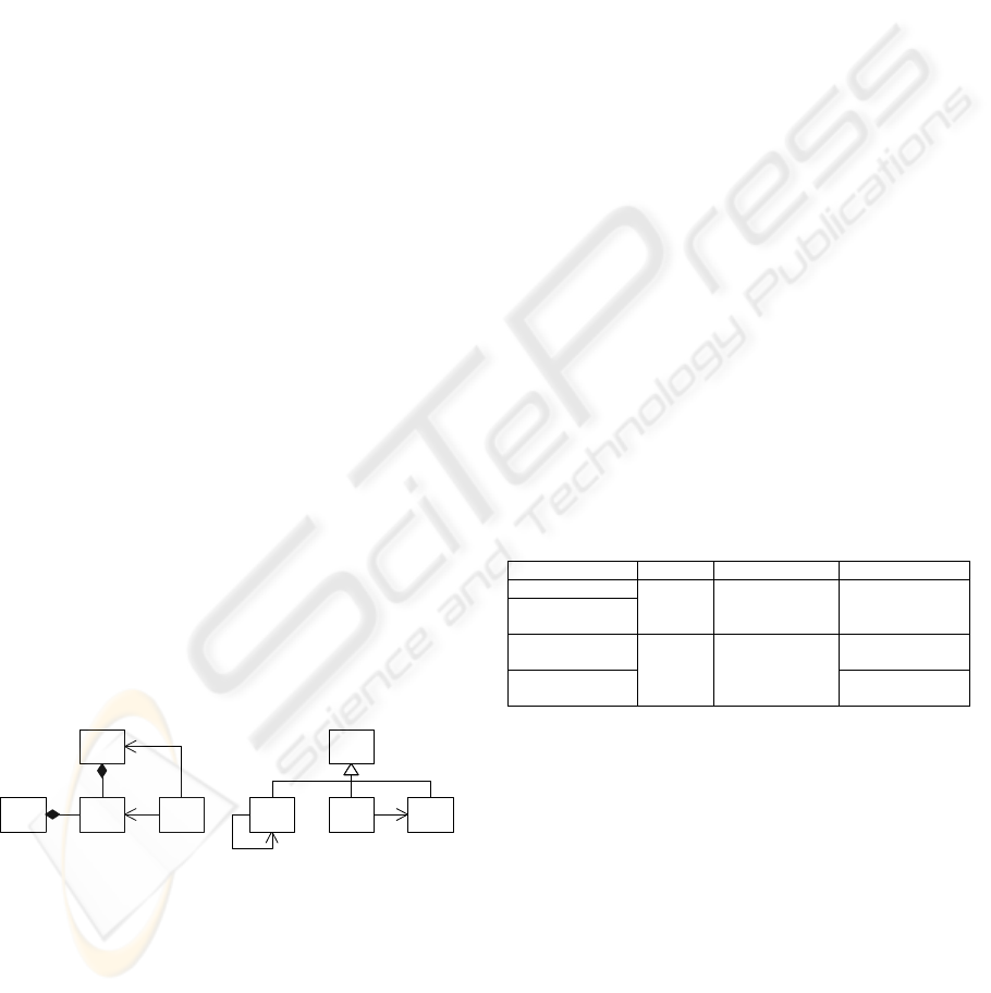
Figure 2 shows two of the found patterns
that were among the most interesting ones. Galicia
generated the concept-IDs, which uniquely identify
the concept within the lattice.
W
Y
Concept ID=941
Nr. of formal objects=21
Nr. of formal attributes=5
Concept ID=678
Nr. of formal objects=20
Nr. of formal attributes=4
K
NMLZX
Figure 2: Two patterns found in Grizzly.
Concept 678 represents a pattern with classes W,
X, Y and Z, where Z has an association with X and
Y. Furthermore, both W and Y have a composition
relationship with X. Analysis of the 20 instances of
this pattern shows that for W fourteen different
classes are present, for X and Y both two, and for Z
three. This indicates that the instances of this pattern
occur in a small number of source-code contexts.
Table 3 shows four example instances of this
pattern. Examination of the Grizzly design
documentation learned that the first instance in
Table 3, with W=BitmapSyncContext, covers a part
of an Interceptor pattern (Buschmann et al, 1999).
This pattern plays an important role in the
architecture of Grizzly. The
BitmapDocEventDispatcher class plays the role of
event Dispatcher, and the BitmapSyncContext the
role of ConcreteFramework. The abstract and
concrete Interceptor classes are not present in the
detected pattern. (The designers of Grizzly omitted
the abstract Interceptor class from the design.) The
EventDispatcherTest class is part of the Grizzly test
code, and plays the role of the Application class in
the Interceptor pattern. The Document class is not
part of the Interceptor pattern. In the Grizzly design
this class is the source of the events handled with the
interceptor pattern.
Observe that the pattern in
Figure 2 does not
contain the “create” relation between the
BitmapDocEventDispatcher (Y) and the
BitmapSyncContext (W) classes (Buschmann et al,
1999). This does not mean that this relationship is
not present; it is omitted from this pattern because
the other pattern instances do not have this
relationship.
Table 3: Example instances of pattern 678.
W X Y Z
BitmapSyncContext
SheetDocEvent-
Dispatcher
Document BitmapDocEvent-
Dispatcher
BitmapDocEvent-
DispatcherTest
FlipSynchronizer InversionWorker-
JobInterceptor
StripeSynchronizer
BasicJob BitmapDocSynchro-
nizer
BitmapDoc-
SynchronizerTest
The other concept shown in Figure 2 (with ID
941) represents a relatively simple pattern with four
classes labeled K, L, M and N. Here, class L, M and
N inherit from K, L has a self-association, and M an
association to N. Analysis of the 21 detected
instances shows that in all cases K refers to the same
class, L to three, and M and N both to six different
classes. This indicates that all instances of this
pattern are used in the same source-code context.
Table 4 shows four of the detected instances of
pattern 941. SplitObjectStorage is an abstract class
from which all workflow-related classes that store
data inherit. The SplitList classes are container
classes, for example for SplitTransition classes. The
SplitTransition classes each represent a single state
transition and are each associated with two
ICSOFT 2007 - International Conference on Software and Data Technologies
20
SplitState objects. These represent the states before
and after the transition.
Table 4: Example instances of pattern 941.
K L M N
SplitTransition
SplitState SplitListOfAllTransitions
SplitNode SplitDoc
SplitListOfAllStates SplitState SplitAttribute
SplitObject-
Storage
SplitListOfAllDocuments SplitDocPart SplitImage-
Sequence
Surprisingly, the Grizzly design documentation
does not mention any of the classes listed in
Table 4.
Analysis of the code shows that these classes are
concerned with workflow management in the
controller, and represent points where Grizzly
interfaces with the rest of the system. Strictly
speaking these classes are not part of Grizzly but of
the workflow-management subsystem of the
controller. However, they are redefined in the
Grizzly source-tree, and hence extracted by
Columbus.
Observe that the two described patterns have a
relatively low complexity. Recall that the two
patterns described here are among the most
interesting ones that are detected. So on average the
complexity of the detected patterns is slightly lower
that of the patterns described here.
2.3.2 Results for RIP Worker
Applying the prototype to the RIP Worker
source code (108 classes) produced a formal context
and lattice with the characteristics shown in
Table 5.
Table 5: Characteristics of the order four context for the
RIP Worker and the corresponding lattice.
Number of formal objects 52037
Number of formal attributes 41
Number of attribute-object relations 170104
Number of formal concepts 3097
Again, the number of formal attributes, 41, is
less than the upper bound |T|·k
2
, which equals 48.
The number of formal objects of the order k context,
|O
k
|, does not exceed the predicted upper bound:
Table 5 represents an order four context, and
|O
k
|=52037
≤
|D|
4
=108
4
≈
1.4·10
8
, so the number
of formal objects is relatively low. As with Grizzly,
this is due to the low connectivity of the classes.
Like with Grizzly, the size of the lattice is
approximately linear with the size of the context
(one order smaller), and the number of formal
objects is much higher than the number of formal
attributes.
With the user-specified size filtering parameters
both set to five (p
x
=p
y
=5), the prototype produced
158 order four concepts (with p
x
=p
y
=4: 799). Like
in Grizzly, the set of patterns found in the RIP
Worker also contains a lot of similar patterns.
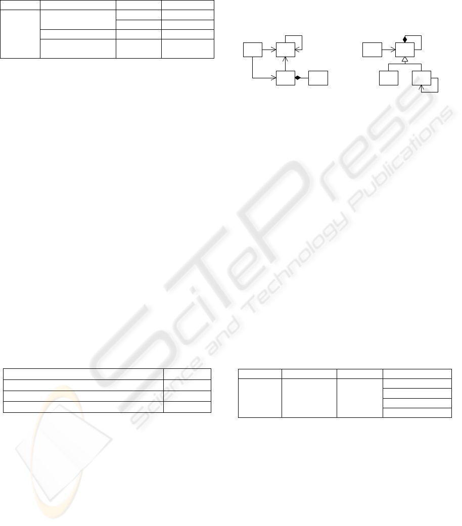
Figure
3
shows two of the patterns found.
L
NM
K
Concept ID=2694
Nr. of formal objects=25
Nr. of formal attributes=5
WZ
YX
Concept ID=2785
Nr. of formal objects=31
Nr. of formal attributes=5
Figure 3: Two patterns found in the RIP Worker.
The output of the filtering module for concept
2694 shows that for class N 25 different classes are
present, but for K, L and M all pattern instances
have the same class. This indicates that all instances
of this pattern are used in the same piece of the
source code.
Table 6 shows four examples of pattern 2694.
All are concerned with job-settings and the
configuration of the system. The
PJT_T_SystemParameters class stores information
about the environment of the system, for example
supported media-formats and -types. The
PJT_T_JobSetting class represents the settings for a
complete job, and is composed of the classes listed
for N. The class listed for L, PJT_T_Product, is used
to detect if the machine can handle a certain job-
specification.
Table 6: Example instances of pattern 2694.
K L M N
PJT_T_MediaColor
PJT_T_MediaWeight
PJT_T_RunLength
PJT_T_Syst
em-
Parameters
PJT_T_Product PJT_T_Job-
Setting
PJT_T_StapleDetails
Analysis of the 31 instances of the pattern for
concept 2785 shows that in all cases W and Y refer
to the same class. X refers to eight different classes
and Z to four. This indicates that all instances of this
pattern are used in the same source-code context.
Table 7 shows four example instances of pattern
2785. None of the listed classes are mentioned in the
RIP Worker design documentation. Examination of
the source code shows that all instances are part of a
GUI library the RIP Worker’s test tools use.
DETECTING PATTERNS IN OBJECT-ORIENTED SOURCE CODE – A CASE STUDY
21
Table 7: Example instances of pattern 2785.
W X Y Z
CDialog CCmdUI
CButton CDialog
CListBox CWinThread
CWnd
CEdit
CFrameWnd
CDataExchange
Similar to the result for Grizzly, the patterns
described for the RIP Worker have a relatively low
complexity. Since these patterns are the most
interesting of the detected patterns, the other patterns
can generally be regarded as uncomplicated.
2.3.3 Observations
Quality of the results. When examining the
prototype’s output for Grizzly and the RIP Worker,
it is clear that better filtering is required. Recall that
filtering for equivalent patterns, as defined by (10),
has not been implemented in the prototype. The
output contains many equivalent patterns, so in
practice this filtering is desired too.
The occurrence of sets of patterns in the output
with small differences represents a more significant
problem. A possible filtering strategy might be to
group highly similar patterns into subsets and
(initially) show only one pattern of each subset of
the user. This requires a measurement for the
difference between patterns. This measurement
could for example be based on the number of edges
(class relations) that must be added and removed to
convert one pattern into another. We leave this as
future work.
After filtering the results manually, the
remaining patterns are of a relatively low
complexity. More complex patterns typically have
one instance and are removed by the pattern
selection module. This means we are not able to
achieve our goal of finding patterns that are useful to
reconstruct architectural views (hypothesis H2).
Several publications report finding large
numbers of design pattern instances in public
domain code and few in industrial code, e.g.
(Antoniol et al, 1998), (Kersemakers, 2005). We
speculate that it could be the case that industrial
practitioners structurally design software in a less
precise way than public domain developers.
Obviously, further experiments are needed to
validate this statement, but it could explain why in
our case study the number of instances of the found
patterns remains fairly low.
Encountered problems. During the fact
extraction process several problems were
encountered. First of all, Columbus consistently
crashed during the compilation of some source files.
Recall that the source files are compiled with the
same compiler as with which they were compiled
during forward engineering. Because they compiled
without errors at that time, the error during fact
extraction must either be caused by an
incompatibility between Columbus and the
Microsoft Visual C++ compiler, or by an error in
Columbus itself.
This problem was encountered once while
analyzing the RIP Worker and ten times while
analyzing the full controller. In all cases, skipping
the source file that triggered the error solved the
problem. Because this only happened once for the
RIP Worker, and not at all for Grizzly, this has little
impact on the results.
The second problem occurred during the linking
step of the fact extraction. In this step the linker of
Columbus combines the compiled source files,
similar to the task of a linker during the generation
of an executable. With the RIP Worker and Grizzly
subsystems no problems were encountered, but with
the complete controller Columbus crashed during
this step. A few experiments revealed that this is
probably caused by the size of the combined abstract
syntax graphs, which is closely related to the size of
the source files. Therefore it was not possible to
extract facts from the full controller with Columbus.
Execution times. Both subsystems have been
analyzed on the same test platform. Table 8 shows
the characteristics of this platform.
Table 8: Test system characteristics.
Processor Pentium 4, 2 GHz
Memory 2 GB
Operating system Windows 2000 SP4
Columbus 3.5
Galicia 1.2
Java 1.4.2_06
Table 9 shows the execution times for the RIP
Worker and Grizzly subsystems for an order four
context (wall-clock time). The time for lattice
construction includes the time needed to import the
formal context into Galicia and export the generated
lattice to an XML file.
For Grizzly the total execution time was 7:44:59
and for the RIP Worker 11:17:17 (hh:mm:ss).
Table 9: Execution times (hh:mm:ss).
Grizzly RIP Worker
1 Fact extraction 0:01:09 0:42:40
2 Context generation 0:26:00 0:36:00
3 Lattice construction 4:41:50 6:57:37
4 Pattern selection 2:36:00 3:01:00
ICSOFT 2007 - International Conference on Software and Data Technologies
22

The patterns the prototype detected in the
Grizzly and RIP Worker source code are relatively
simple. Possibilities to produce more interesting
patterns are:
1. Extending the size of the input to, for example,
multiple subsystems of the controller.
2. Increasing the order of the context. This
increases the number of classes in the patterns,
and hence their complexity.
3. Introducing partial matches.
The third possibility, partial matches, requires
fundamental changes to the method. If FCA would
still be used, these changes would increase the size
of the lattice significantly and hence also the
execution time of the lattice construction step.
The first two options have the disadvantage that
they increase the size of the data that is processed.
This affects the running time of all modules. Recall
that the computational complexity of the algorithms
each of the modules uses is polynomial with the
number of classes and exponential with the order of
the context. Based on this, and the executing times
in Table 9, we concluded that, from a performance
point of view it is not practical to use the prototype
to reconstruct architectural views of the complete
controller: the controller contains about ten to
twenty times more classes than the two subsystems
used in the experiment.
3 CONCLUSIONS AND FUTURE
WORK
Pattern detection methods that are based on a pattern
library have been applied frequently and their
properties are relatively well known. A disadvantage
is that they require upfront knowledge of the used
patterns and their precise implementation.
Implementation variations make the latter difficult to
specify. The pattern detection method we applied is
based on Formal Concept Analysis and does not
require a pattern library.
The method proved to be able to detect
frequently used design structures in source code
without upfront knowledge of the expected
constructs, thereby confirming our hypothesis H1 in
section 2.1.
However, even the detection of relatively simple
structures in relatively small pieces of source code
required a lot of calculations. For performance
reasons no contexts of orders large than four could
be analyzed, so the detected patterns consisted of
four classes or less. Although large numbers of
pattern instances were detected, these were typically
confined to a few areas of the source code. Because
it was not possible to detect patterns with six classes
or more, we failed to confirm hypothesis H2.
Since this is inherent to the used algorithms, the
application of this technique to reconstruct
architectural views of large object-oriented systems,
more specific, systems with the size of the
controller, is not considered practical. It is possible
to detect design patterns in its subsystems though.
These have a size of about five to ten percent of the
complete controller system.
Besides performance issues, the reduction of the
large number of similar patterns in the output is also
important. Based on the complexity of the patterns
we filtered the output, but the results show that more
advanced filtering is necessary in order for the
method to be useful. It might also be possible to
group similar patterns into groups and show a single
pattern of each group to the user. The similarity of
patterns could be based on the number of edges that
must be added and removed to transform them into
each other.
Finding frequently used design constructs in the
source code essentially finds frequently occurring
subgraphs in the class graph. An alternative to the
pattern detection currently used might be to use
graph compression algorithms that are based on the
detection of recurring subgraphs. We have built a
small prototype that uses the Subdue algorithm
(Jonyer et al, 2001). This algorithm creates a list of
recurring subgraphs and replaces all occurrences of
these subgraphs with references to this list.
However, when this algorithm is used for pattern
detection, the fact that the algorithm looks for
perfectly identical subgraphs causes problems. The
intertwining of structures often encountered in
practice caused this prototype to find no patterns at
all in two subsystems (Grizzly and the RIP Worker)
of the controller. Lossy graph compression
algorithms might introduce the required fuzziness.
REFERENCES
Antoniol, G., R. Fiutem, L. Cristoforetti (1998). Design
Pattern Recovery in Object-Oriented Software. Proc.
6th International Workshop on Program
Comprehension, pp. 153-160.
Arévalo, G., S. Ducasse, O. Nierstrasz (2003).
Understanding classes using X-Ray views. Proc. of
2nd International Workshop on MASPEGHI 2003
(ASE 2003), pp. 9-18.
Ball, T. The concept of Dynamic Analysis (1999).
Foundations of Software Engineering, Proc. 7th
DETECTING PATTERNS IN OBJECT-ORIENTED SOURCE CODE – A CASE STUDY
23

European Software Engineering Conference / 7th
ACM SIGSOFT Symposium on Foundations of
Software Engineering, pp. 216-234.
Bassil, S., R.K. Keller (2001). Software Visualization
Tools: Survey and Analysis. Proc. 9th International
Workshop on Program Comprehension (IWPC’01),
pp. 7-17.
Beck, K., J.O. Coplien, R. Crocker, L. Dominick, G.
Meszaros, F. Paulisch, J. Vlissides (1996). Industrial
Experience with Design Patterns. Proc. 18th
International Conference on Software Engineering
(ICSE-18), pp. 103-114.
Bordat, J.P. (1986). Calcul pratique du treillis de Galois
d’une correspondance. Math. Sci. Hum., 96, pp. 31-47.
Buschmann, F., R. Meunier, H. Rohnert, P. Sommerlad,
M. Stal (1999). Pattern-Oriented Software
Architecture: A System of Patterns. John Wiley and
Sons Ltd, Chichester, England.
Chikovsky, E.J., J.H. Cross (1990). Reverse Engineering
and Design Recovery: A taxonomy. IEEE Software,
7(1), pp. 13-17.
Columbus/CAN (2003). Setup and User’s Guide to
Columbus/CAN, Academic Version 3.5. FrontEndART
Ltd.
Deursen, A. van (2002). Software Architecture Recovery
and Modelling [WCRE 2001 Discussion Forum
Report]. ACM SIGAPP Applied Computing Review,
10(1).
Gamma, E., R. Helm, R. Johnson, J. Vlissides (1995).
Design Patterns: elements of reusable object-oriented
software, fifth edition. Addison-Wesley.
Galicia Project.
http://www.iro.umontreal.ca/~galicia/.
Ganther, B., R. Wille (1998). Applied lattice theory:
formal concept analysis. In: General Lattice Theory,
G. Grätzer editor, Birkhäuser Verlag.
Hahsler, M. (2003). A Quantitative Study of the
Application of Design Patterns in Java. Technical
report 1/2003, University of Wien.
Hassan, A.E., R. Holt (2004). The Small World of
Software Reverse Engineering. Proc. 2004 Working
Conference on Reverse Engineering (WCRE’04), pp.
278-283.
Jonyer, I., D.J. Cook, L.B. Holder (2001), Graph-Based
Hierarchical Conceptual Clustering. Journal of
Machine Learning Research, 2, pp. 19-43.
Keller, R.K., R. Schauer, S. Robitaille, P. Pagé (1999).
Pattern-Based Reverse-Engineering of Design
Components. Proc. 21st International Conference on
Software Engineering (ICSE'99), pp. 226-235.
Kersemakers, R., E. Dortmans, L. Somers (2005).
Architectural Pattern Detection - A Case Study. Proc.
Ninth International Conference on Software
Engineering and Applications (SEA 2005), Phoenix,
November 14-16, pp. 125-133.
Kuznetsov, S.O., S.A. Obëdkov (2001). Comparing
performance of algorithms for generating concept
lattices. Proc. 9th IEEE International Conference on
Conceptual Structures (ICCS ’01), pp. 35-47.
O’Brien, L., C. Stoermer, C. Verhoef (2002). Software
Architecture Reconstruction: Practice Needs and
Current Approaches. SEI Technical Report CMU/SEI-
2002-TR-024, Software Engineering Institute,
Carnegie Mellon University.
Prechtelt, L., B. Unger, W.F. Tichy, P. Brössler, L.G.
Votta (2001). A Controlled Experiment in
Maintenance Comparing Design Patterns to Simpler
Solutions. IEEE Transactions on Software
Engineering, 27(12), pp. 1134-1144.
Prechtelt, L., B. Unger-Lamprecht, M. Philippsen, W.F.
Tichy (2002). Two Controlled Experiments Assessing
the Usefulness of Design Pattern Documentation in
Program Maintenance. IEEE Transactions on
Software Engineering, pp. 595-606.
Sartipi, K., K. Kontogiannis (2003). Pattern-based
Software Architecture Recovery. Proc. Second
ASERC Workshop on Software Architecture.
Siff, M., T. Reps (1997). Identifying Modules via Concept
Analysis. Proc. International Conference on Software
Maintenance (ICSM '97), pp. 170-179.
Siff, M., T. Reps (1998). Identifying Modules via Concept
Analysis. Technical Report TR-1337, Computer
Sciences Department, University of Wisconsin,
Madison, WI, USA.
Sim, S.E., R. Koschke (2001). WoSEF: Workshop on
Standard Exchange Format. ACM SIGSOFT
Software Engineering Notes, 26, pp. 44-49.
Snelting, G. (1996). Reengineering of Configurations
Based on Mathematical Concept Analysis. ACM
Transactions on Software Engineering and
Methodology, 5(2), pp. 146-189.
Snelting, G. (2000). Software Reengineering Based on
Concept Lattices. Proc. European Conference on
Software Maintenance and Reengineering (CSMR
2000), pp. 1-8.
Tilley, T., R. Cole, P. Becker , P. Eklund (2003). A Survey
of Formal Concept Analysis Support for Software
Engineering Activities. Proc. First International
Conference on Formal Concept Analysis - ICFCA'03,
G. Stumme, Springer-Verlag.
Tonella, P., G. Antoniol (1999). Object Oriented Design
Pattern Inference. Proc. International Conference on
Software Maintenance (ICSM’99), pp. 230-238.
Tonella, P., G. Antoniol (2001). Inference of Object
Oriented Design Patterns. Journal of Software
Maintenance and Evolution: Research and Practice,
13(5), published online Oct., pp. 309-330.
Valtchev, P., D. Grosser, C. Roume, M.R. Hacene (2003).
Galicia: an open platform for lattices. In: Using
Conceptual Structures: Contributions to the 11th Intl.
Conference on Conceptual Structures (ICCS'03), pp.
241-254, Shaker Verlag.
Wille, R. (1981). Restructuring lattice theory: An
approach based on hierarchies of concepts. In: I. Rival,
editor, Ordered Sets, pp. 445-470. NATO Advanced
Study Institute.
ICSOFT 2007 - International Conference on Software and Data Technologies
24
