
MODEL-DRIVEN DEVELOPMENT OF GRAPHICAL TOOLS
Fujaba Meets GMF
Thomas Buchmann, Alexander Dotor and Bernhard Westfechtel
University of Bayreuth, Universitaetsstrasse 30, 95440 Bayreuth, Germany
Keywords:
Model Driven Development, Rapid Prototyping, Story Driven Modeling, Graphical Modeling Framework.
Abstract:
In this paper we describe and evaluate our combination of the Fujaba CASE-Tool with the Graphical Modeling
Framework (GMF) of the Eclipse IDE. We created an operational model with Fujaba and used it as input for
a GMF editor generation process. This allows us to introduce a new approach for generating fully operational
models including graphical editors for model representation and transformation. By making our developement
process explicit this paper acts as a guide for applying this approach to other projects as well.
1 MOTIVATION
Model-driven software development has gained in-
creasing attention during the last years. Executable
models promise to improve the productivity of soft-
ware engineers significantly. In particular, in the con-
text of object-oriented software engineering numer-
ous approaches have been developed to generate exe-
cutable code from higher-level models.
Model-driven software development may be ap-
plied to different parts of a software system. The ap-
plication logic is concerned with the structure and be-
havior of the data on which the system operates. In
an interactive system, the operations provided by the
application logic are invoked through a user interface
which presents the data of the application in various
ways.
In this paper, we address the integration of the
Graphical Modeling Framework (GMF) with the
object-oriented CASE tool Fujaba. GMF allows the
fast generation of graphical editors for any object-
oriented data model based on the Eclipse Modeling
Framework (EMF) and the Eclipse Graphical Edit-
ing Framework (GEF) (ecl, 2006d). Fujaba supports
model-driven development by generating executable
code from object-oriented models which are com-
posed of class, state, and story diagrams (combina-
tions of activity and communication diagrams).
With GMF, graphical editors may be generated
rapidly. However, their functionality is restricted to
predefined elementary graph operations such as inser-
tion and deletion of single nodes and edges. This re-
striction is due to the fact that EMF focuses on struc-
ture and lacks support for generating behavioral mod-
els, i.e., method bodies must still be implemented
manually. Fujaba closes this gap since it generates
fully operational models.
Thus, combining both approaches supports
model-driven development of interactive systems,
covering both user interface and application logic.
Below, we demonstrate step by step the development
process for the combined application of Fujaba and
GMF, and show that the execution of this process sig-
nificantly reduces the development time for interac-
tive systems with a graphical user interface.
2 TECHNOLOGY OVERVIEW
Before introducing the main features of GMF it is
necessary to get an overview of EMF and GEF first.
Please note that due to the space limitations of this
paper it is not possible to give an full overview of
all three frameworks. Readers who are interested in
a more detailed and complete introduction to EMF,
GEF and GMF we propose a further reading of
(ecl, 2006b), (ecl, 2005b) and (ecl, 2006c) as well
425
Buchmann T., Dotor A. and Westfechtel B. (2007).
MODEL-DRIVEN DEVELOPMENT OF GRAPHICAL TOOLS - Fujaba Meets GMF.
In Proceedings of the Second International Conference on Software and Data Technologies - SE, pages 425-430
DOI: 10.5220/0001332604250430
Copyright
c
SciTePress
as (Z
¨
undorf, 2001) to learn more about Fujaba and
SDM.
2.1 Eclipse Modeling Framework
EMF is a framework for Eclipse that allows the spec-
ification of models based on the Ecore
1
metamodel
(ecl, 2005a).
Based on the Ecore model definition it is possi-
ble to generate a (non-operational) model implemen-
tation. The model implementation consists of inter-
faces only, so if we had not used Fujaba for generat-
ing our model we would still have to implement all
complex methods or - in Ecore terminology - all in-
stances of
EOperation.
But in either case we must
still create a graphical editor both to view our model
as a graph and to call our
EOperation
instances for
model transformations.
2.2 Graphical Editing Framework
GEF is an Eclipse framework that provides support
for the uniform implementation of graphical edi-
tors. GEF is based on the
Model View Controller
(MVC) pattern (Freeman et al., 2004) which is widely
used for object oriented GUI implementations. But
most GUIs implement MVC in a non-uniform way,
which limits the extensibility and accessibility of
complex GUIs. GMF provides the necessary data
structures for designing and implementing complex
graphical editors. As suggested by the MVC pat-
tern GEF separates the data model from its graphi-
cal representation - the view. Data model and view
are linked by the controller - called editpart in GEF
- which both updates the view if the data model
changes and passes change requests from the view to
the data model (ecl, 2005b).
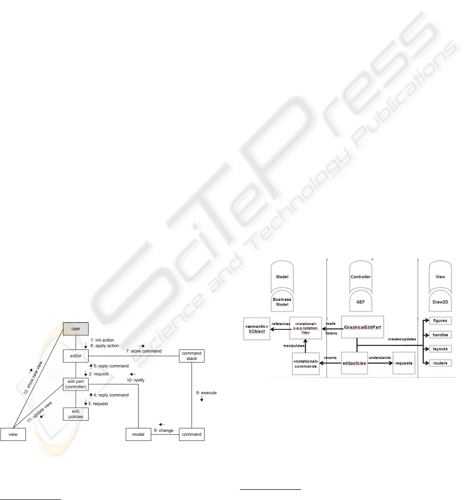
Figure 1: Communication diagram of a GEF editor interac-
tion.
Figure 1 shows a communication diagram of a
user-editor interaction: Once the user initiates an ac-
1
an UML-dialect and a variant of the OMG proposal for
Essential Meta Object Facility (EMOF)
tion via the GUI (1) the editor sends a request to all
edit parts (2). Each edit part forwards the request to
its edit policies (3). If a policy is responsible for the
request it returns a command (4) that is propagated to
the editor (5). Once the user applies the command (6)
it is stored on the command stack (7) for undo/redo-
functionality and finally executed (8). During execu-
tion the command applies its changes to the model
(9). Affected model elements notify their edit part
about the changes (10), so each notified edit part can
update its view element (11). Finally the updated
view presented to the user (12).
With the help of GEF, graphical editors may be
developed quite rapidly. However, this still requires
a significant amount of manual implementation (see
Section 6).
2.3 Graphical Modeling Framework
GMF
2
combines both EMF and GEF for a generative
approach to create graphical editors. GMF is sepa-
rated into two components: a runtime component
and a generator component. The runtime compo-
nent provides facilities for viewing and manipulating
a graphical model. The generator component takes
an Ecore-based model – any EMF-model – and maps
it onto the runtime component. Therefore two models
exist in GMF: the Ecore-based data model – called se-
mantic model – and the GMF-internal runtime model
– called notational model. The runtime component
synchronizes both models (ecl, 2006d).
Figure 2: Components of the GMF and their relationships
(ecl, 2006a).
Figure 2 (ecl, 2006a) gives a rough overview about
the various components of GMF and its relationships.
As depicted by the rounded boxes GMF is split ac-
cording to the MVC pattern into Business Model,
GEF-Controller and Draw2D-View. The Business
Model is separated into an Ecore-based semantic
2
GMF was released in June 2006 and counts as work in
progress, so the only publications available are slides and
website-articles (ecl, 2006c).
ICSOFT 2007 - International Conference on Software and Data Technologies
426
model and a notational model. Furthermore the no-
tational model is GEF-compliant
3
by separating no-
tational commands from notational data. The GEF-
Controller listens via GraphicalEditPart to notational
data model changes and updates the Draw2D-View
accordingly. Additionally every GraphicalEditPart
reacts on requests and provides the corresponding no-
tational commands if responsible.
We continue now with showing how to generate a
simple editor with GMF for a sample model. The ex-
ample provides more insight into the GMF but please
note that due to its complexity an extensive descrip-
tion of GMF is out of the scope of this paper. Please
refer to (ecl, 2006d) or (ecl, 2006c) for further read-
ing.
2.4 Fujaba
Fujaba (Z
¨
undorf, 2001) is a powerful environment for
developing executable models with the help of class,
story, and state diagrams. Fujaba has been used in
numerous research projects and is being developed
jointly at multiple sites; work on Fujaba is presented
in a workshop series (Giese and Westfechtel, 2006).
The most distinctive feature of Fujaba are story di-
agrams, which combine activity and communication
diagrams. Fujaba generates executable code from
story diagrams. By default, the code generator pro-
duces plain Java code. While GEF does not constrain
the model to be used, GMF requires an EMF model.
To make the integration of Fujaba and GMF work,
the Fujaba development team (located at Kassel, Ger-
many) extended the code generator in order to pro-
duce EMF models.
3 CREATING A FUJABA MODEL:
DYNAMIC TASK NETS
Before we can start the generative process of GMF we
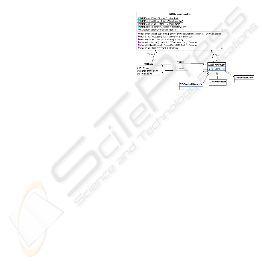
have to create a model first. Figure 3 depicts an UML
class diagram of our sample model: a Dynamic Task
Net (DTN) (Heimann et al., 1997). A DTN is a model
used for keeping track of tasks and their relation-
ships in development process management systems.
Instances of class
DTNDynamicTaskNet
represent a
complete DTN. Each DTN consists of tasks (class
DTNTask
) and relationships (class
DTNConnection
).
Additionally we have three types of relationships:
3
To provide undo/redo functions, GEF requires the sep-
aration of data and operations. Therefore each operation in
the notational model has an associated notational command
class (see:Command Pattern (Freeman et al., 2004))
1. a control flow relationship (class
DTNControl-
Flow
) to represent temporal dependencies, i.e.
“Task A must finish before Task B begins”.
2. a subtask relationship (class
DTNSubtask-
Hierarchy
) to represent compositions, i.e. “Task
A consists of two tasks: Task A1 and Task A2”.
3. a feedback relationship (class
DTNFeedbackFlow
)
to represent backward dependencies, i.e. “Execu-
tion of Task B suggests a rework of Task A due to
new insights into the problem”.
Figure 3: Class diagram of the Dynamic Task Net (DTN)
model.
It is important to notice that the application stud-
ied here significantly goes beyond just a standard
graphical editor. The process management system
supports seamless interleaving of editing and execu-
tion of dynamic task nets. All operations have to
maintain numerous consistency constraints, and in
general they affect subgraphs of the DTN rather than
just single nodes, edges, and attributes. The behav-
ior of DTNs is specified with a comprehensive set of
story diagrams, which, however, cannot be presented
here due to the lack of space.
4 GENERATING A SIMPLE GMF
EDITOR
Once we have created our model in Fujaba, we are
able to generate both the Ecore-based model and the
implementation of our complex methods. Now we
can start generating our first prototype by executing
the following seven steps (ecl, 2006d):
1. Create/Generate model: In this step the model
is created with Fujaba first. Then its implemen-
tation is generated both by Fujaba and the EMF
code generation. Instead of creating an Ecore-
based model definition manually we generate the
model definition and the method implementation
MODEL-DRIVEN DEVELOPMENT OF GRAPHICAL TOOLS - Fujaba Meets GMF
427
with Fujaba. Note that only the method imple-
mentation is generated by Fujaba – not the inter-
faces. We use the ability of the EMF code gener-
ation to merge already existing implementations
into the EMF code generation process and gen-
erate the interfaces from the Ecore-based model
definition. Now we have a fully operational EMF
model.
2. Create Graphical Definition: In this step the el-
ements of the notational model (i.e. node figure,
labels, etc.) are defined.
3. Create Tooling Definition: In this step the palette
entries of the editor are defined.
4. Create Mapping Definition: In this step infor-
mation from the model, graphical and the tooling
definition are combined. For each model element
a graphical element (if any) is chosen as well as
a tooling element. Examples are a class from the
model which is depicted as circle or an attribute
that is shown by a label.
5. Create Generator Model: In this step the map-
ping definition is translated into a generator
model.
6. Adjust Generation Parameters: In this step var-
ious parameters for the plug-in generation can be
manipulated, i.e. class names of selected plug-in
classes.
7. Generate Diagram Plug-in: This is the final step
of the generation process. It produces a fully op-
erable graphical editor as Eclipse plug-in.
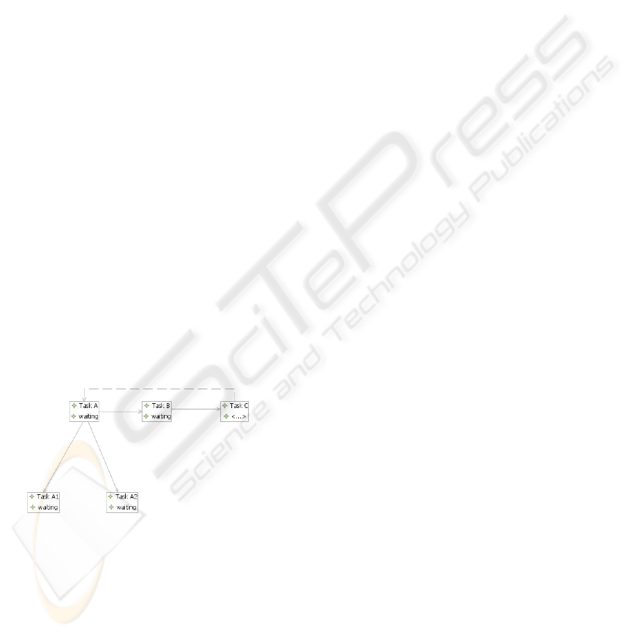
Figure 4 shows a sample DTN instance in a GMF
editor.
Figure 4: GMF diagram of a simple DTN instance.
5 EXTENDING THE EDITOR
Once the editor has been generated it turns out that it
is missing typical functionality that is expected from
any generated tool – like support for calling the gen-
erated complex model operations. In the following
section the solution to several problems is presented
first, discussing the open ones afterward.
5.1 Solved Problems
The editor generated so far does not yet provide the
functionality we expect from the final graphical tool.
Executable code has been generated from the Fu-
jaba model, but the corresponding operations cannot
be called via the generated editor. As mentioned,
these operations have to preserve the consistency con-
straints of the DTN model and may affect large parts
of the task net (e.g., suspension of all active tasks in
some task hierarchy).
To support the call of
EOperations
of a semantic
model element via the editor we want to have a con-
text menu. This menu must only show up if the fig-
ure associated with the model element is selected. To
support this behavior we have to customize the gener-
ated editor. Luckily GMF is designed for extensibil-
ity (ecl, 2006d) so we must create only another plug-
in-project. First we have to design our menu struc-
ture and actions as described in (Clayberg, 2006). We
want to relate specific menus to specific figures so we
have to chose the right
EditPart
-class to attach the
menu to. Note that the menus are related to the con-
troller (an
EditPart
) and not the model (a semantic
or notational model element).
Second we have to implement the actions for the
menu entries. Each action must gather all neces-
sary parameters from the user before it calls its corre-
sponding method in the semantic model. So a dialog
for every action has to be implemented. But simply
calling the appropriate method in the semantic model
fails: GMF uses the EMF Transaction framework to
access the semantic model. So we have to implement
subclasses of
AbstractTransactionalCommand
as
wrapper for each method call. Additionally the
operation has to be registered in the current
TransactionalEditingDomain
or it will be rejected
by the EMF Transaction framework.
Last but not least we have replaced the gen-
erated default commands for basic model trans-
formations (i.e. adding or deleting a node) with
our own basic commands. We can reuse the
TransactionalCommands
we implemented for the
menu actions above. GMF allows us to attach a
so called
EditHelper
to any type of our seman-
tic model. An
EditHelper
receives every request
that is generated due to the users actions and is
affecting the appropriate type. Our implementa-
tion of the
EditHelper
replaces the default com-
mand associated with the request with our appropri-
ate
TransactionalCommand
. Whenever the default
command would have been executed our command is
executed instead.
ICSOFT 2007 - International Conference on Software and Data Technologies
428
5.2 Open Problems
We encountered several problems with the default be-
havior of the synchronization of the semantic and the
notational model. Whenever a semantic model ele-
ment gets deleted or moved the view is not updated
accordingly. This led to two manually implemented
workarounds in the generated model, various bug re-
ports and a discussion in the GMF-developer forum.
For us it is obvious that a view has to be deleted by
default if it is not existing in the semantic model any-
more. Problems due to multi user access to a model
do not have to be solved by the synchronization mech-
anism but must be addressed separately. Up to date
there has been no decision if this should be default
behavior in GMF or not.
6 EVALUATION
In (Buchmann and Dotor, 2006) we created a pro-
totype of a graphical process management tool with
GEF. In table 1 we compare the lines of manually im-
plemented code of the GEF-based tool and the GMF-
based tool of this paper. Additionally we compare the
implementation effort as an indicator for ease of work
and we count the number of class files – both imple-
mented manually or generated – as an indicator for
framework-induced complexity.
Table 1: Comparison of effort and complexity of GEF- and
GMF-based editor creation.
GEF editor GMF-editor
LOC manually 4330 618
#classes manually 80 15
#classes overall 103 111
development time ≈ 160h ≈ 12h
The development time of our GMF-based tool is
more than ten times smaller than the development
time of our GEF-based tool: Seven times less code
has to be implemented in six times fewer classes. Sur-
prisingly the number of overall classes in the GMF-
based tool is roughly the same as in the GEF-based
tool. One might expect to have more classes in the
more complex framework.
When it comes to default functionality and exten-
sibility of the GMF editor it turned out that the editor
is easily extensible if the developer is familiar with
the GMF. The familiarization with GMF is a labori-
ous task due to the lack of documentation and publi-
cations. Table 2 gives an overview of the expenditure
of time in hours for the generation and the customiza-
tion step – both for a developer familiar and unfamil-
iar with GMF.
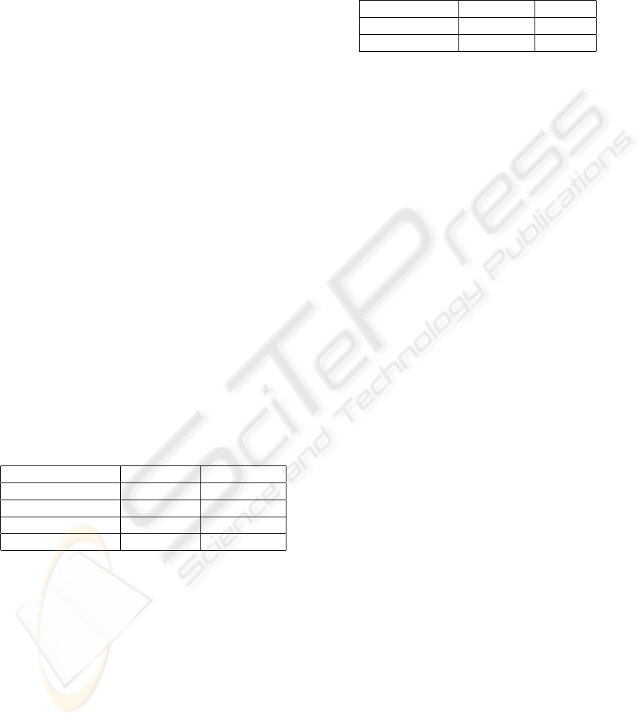
Table 2: Comparison of expenditure of time for developers
familiar and unfamiliar with GMF.
unfamiliar familiar
Generation ≈ 16h ≈ 8h
Customization ≈ 40h ≈ 4h
Familiarity with GMF and its related technologies
speeds up development time dramatically. Especially
the customization of the graphical tool was approx-
imately ten times faster once the first prototype has
been created.
These results lead to the conclusion that the de-
velopment of Fujaba and GMF-based prototypes de-
creases the development time dramatically. But like
any large framework GMF requires some time to be-
come familiar with it. Once the first tool has been
developed and extended development time decreases.
Even when the developer changes the project he can
keep up the pace as GMF does not change.
7 RELATED WORK
The Fujaba environment includes Dobs (Geiger and
Z
¨
undorf, 2002), a dynamic object browser for visual-
izing object structures at run time and for executing
operations on these object structures. As part of Fu-
jaba4Eclipse, Dobs may be run as an Eclipse plug-in
(eDobs). Both Dobs and eDobs serve as debugging
tools and have not been designed as graphical editors.
UPGRADE (B
¨
ohlen et al., 2002) is a univer-
sal platform for graph-based development which
has originally been used PROGRES-based models
(Sch
¨
urr et al., 1999). Recently, it has been integrated
with Fujaba, as well. With UPGRADE, graphical
editors may be generated for arbitrary graph models
which operate as stand-alone tools. In contrast, our
work exploits technology developed in the context of
Eclipse. Since our graphical editors may be run as
Eclipse plug-ins, we may benefit from the function-
ality provided by the Eclipse infrastructure and inte-
grate smoothly with other tools based on Eclipse.
The TIGER project (Ehrig et al., 2005) is based on
AGG, an approach to graph transformations based on
category theory. It is dedicated to the automatic gen-
eration of GEF editors using graph transformations,
in contrast to our work, which uses GMF for editor
generation. Therefore we may benefit from further
developments for GMF, i.e. design tools for graphical
elements and sophisticated wizards for the generation
process. Furthermore our editors are extensible like
MODEL-DRIVEN DEVELOPMENT OF GRAPHICAL TOOLS - Fujaba Meets GMF
429

any other GMF-editor.
8 CONCLUSION
We have demonstrated model-driven development of
graphical tools using Fujaba and GMF. While GMF
lacks support for behavioral models, Fujaba closes
this gap by generating executable code from story di-
agrams. The tables given in Section 6 indicate that
the development effort following our process is fairly
small, i.e., productivity is increased significantly. On
the other hand, there are still several problems to be
solved by ongoing and future work. The most im-
portant problem concerns the implementation of more
complex commands than the basic add and delete
commands: Even with the planned enhancement of
the GMF tooling definition to support the generation
of menus and actions is it necessary to implement di-
alogs, actions and
TransactionalCommands
to allow
sophisticated transformations of the semantic model.
We will evaluate whether it is possible to enhance Fu-
jaba to generated dialogs and actions. Furthermore
we plan to investigate whether it is worth the effort to
override the proposed GMF generation process, de-
veloping some kind of Fujaba graphical editor gener-
ation plug-in.
ACKNOWLEDGEMENTS
We would like to thank the whole Fujaba community
for developing and extending the CASE-tool but es-
pecially Leif Geiger from the University of Kassel for
implementing the EMF code generation.
REFERENCES
(2005a). The Eclipse Modeling Frame-
work (EMF) Overview. Eclipse Foun-
dation.
http://dev.eclipse.org/-
viewcvs/indextools.cgi/*checkout*/-
org.eclipse.emf/doc/org.eclipse.emf.doc/-
references/overview/EMF.html
– last visited:
27/10/2006.
(2005b). GEF Programmer’s Guide. IBM Corporation.
http://help.eclipse.org/
.
(2006a). Creating your own Domain Specific Modeler us-
ing GMF. Borland, IBM.
http://eclipsezilla.-
eclipsecon.org/attachment.cgi?id=175
– last
visited: 21/03/2007.
(2006b). EMF - Eclipse Modeling Framework. Eclipse
Foundation.
http://www.eclipse.org/emf
– last
visited: 21/03/2007.
(2006c). GMF - Graphical Modeling Framework. Eclipse
Foundation.
http://www.eclipse.org/gmf
– last
visited: 21/03/2007.
(2006d). Introduction to the Eclipse Graphi-
cal Modeling Framework. Borland, IBM.
http://eclipsezilla.eclipsecon.org/-
php/attachment.php?bugid=1
– last visited:
21/03/2007.
B
¨
ohlen, B., J
¨
ager, D., Schleicher, A., and Westfechtel, B.
(2002). Upgrade: A framework for building graph-
based interactive tools. Electronic Notes in Theoreti-
cal Computer Science, 72(2):113–123.
Buchmann, T. and Dotor, A. (2006). Building graphical
editors with gef and fujaba. In FUJABA Days 2006
proceedings, pages 47–51, Paderborn, Germany. Uni-
versitt Paderborn.
Clayberg, E. (2006). Eclipse. Building Commercial-Quality
Plug-Ins. Addison-Wesley Professional.
Ehrig, K., Ermel, C., H
¨
ansgen, S., and Taentzer, G. (2005).
Generation of visual editors as eclipse plug-ins. In
ASE ’05: Proceedings of the 20th IEEE/ACM in-
ternational Conference on Automated software engi-
neering, pages 134–143, New York, NY, USA. ACM
Press.
Freeman, E., Freeman, E., and Sierra, K. (2004). Head First
Design Patterns, volume 1 of Head First. O’Reilly
Media, Sebastopol (CA), USA.
Geiger, L. and Z
¨
undorf, A. (2002). Graph based debugging
with fujaba. Electronic Notes in Theoretical Computer
Science, 72(2):124–131.
Giese, H. and Westfechtel, B., editors (2006). FUJABA
Days 2006 proceedings, Paderborn, Germany. Univer-
sitt Paderborn.
Heimann, P., Krapp, C.-A., and Westfechtel, B. (1997).
Graph-based software process management. Interna-
tional Journal of Software Engineering and Knowl-
edge Management, 7(4):431–455.
Sch
¨
urr, A., Winter, A., and Z
¨
undorf, A. (1999). The PRO-
GRES approach: Language and environment. In
Ehrig, H., Engels, G., Kreowski, H.-J., and Rozen-
berg, G., editors, Handbook on Graph Grammars and
Computing by Graph Transformation: Applications,
Languages, and Tools, volume 2, pages 487–550.
World Scientific: Singapore.
Z
¨
undorf, A. (2001). Rigorous Object Oriented Software De-
velopment. PhD thesis, University of Paderborn, Ger-
many.
ICSOFT 2007 - International Conference on Software and Data Technologies
430
