
AN IMPROVEMENT TO THE MIXED MDA-SOFTWARE
FACTORY APPROACH: A REAL CASE
Gustavo Muñoz Gómez and Juan Carlos Granja
Grupo de Investigación de Lenguajes y Sistemas Informáticos e Ingeniería del Software (GILSIIS)
Escuela Técnica Superior de Ingenierías Informática y de Telecomunicacion, Universidad de Granada
C/ Periodista Daniel Saucedo Aranda s/n 18071 Granada, Spain
Keywords: MDA-software factories; product line requirement engineering; state-subsidized healthcare service.
Abstract: In this article, we will offer a solution to the mixed MDA–software factory model which enables greater
satisfaction of the requirements of a product line based on work by Gary Chastek’s team with the
application of the required transformations for generating the three components necessary for the creation of
product families using the mixed approach. In order to validate the chosen representation and
transformations, we will focus on a real case which appeared in a previous article by Muñoz et al. (2006).
Interesting option is to explore in greater depth the requirements of the family of programs that we want to
create and to obtain the product line, framework and specific language from these. For this purpose, we will
use Chastek et al.’s representation system (2001) which allows us to represent the requirements using three
CIM models and a dictionary of specific terms. The mixed MDA–software factory approach (Muñoz, J.,
Pelechano, V.) enables the advantages of both approaches to be enjoyed using the PIM models as a starting
point.
1 INTRODUCTION
MDA (Millar, J., Mukerji, J., 2003) is a software
development framework which defines a new way of
constructing software in which system models are
used on different levels of abstraction to guide the
entire development process from system analysis
and design to system maintenance and its integration
with future systems. The mixed MDA–software
factory approach (Muñoz, J., Pelechano, V., 2005)
enables product lines to be created and the
variability of the different products comprising a
family to be maintained. As the same in the GECAC
practical case (Muñoz, G., Granja, J.C., Sempere, C.,
2006), this approach is perfectly valid for resolving
the problem presented in the article: that of solving
the problem of financially managing state-subsidized
places in healthcare centres (Diputación de
Granada). We also the same that it was necessary to
obtain a product line, a framework and a specific
programming language that would provide the
variability necessary for creating the different
products.
2 CURRENT SITUATION
Product line analysis is equivalent to requirement
engineering for the product lines of an intensive
software system and involves eliciting, analyzing,
specifying and verifying the requirements of a
product line. This is the perspective of the
requirement analysis of the requirement engineering
rules in the development of a product line as
presented by Chastek et al. (2001).
2.1 Model Driven Architecture (MDA)
MDA attempts to separate the specification of a
system’s operations and data on one side from the
details of the platform on which the system will be
constructed on the other. In this way and in general,
software development with MDA can be divided
into four stages: construction of a computation
independent model (CIM); transformation into one
or several platform independent models (PIM);
transformation of the previous model into one or
several platform-specific models (PSM); and code
generation from each PSM.
387
Muñoz Gómez G. and Carlos Granja J. (2007).
AN IMPROVEMENT TO THE MIXED MDA-SOFTWARE FACTORY APPROACH: A REAL CASE.
In Proceedings of the Second International Conference on Software and Data Technologies - SE, pages 387-392
DOI: 10.5220/0001336703870392
Copyright
c
SciTePress

3 PROBLEMS CONSIDERED
As we have seen in previous sections, there are two
solutions: Chastek et al.’s system of models and data
dictionary (2001) enabling the requirements of a
product line to be represented and validated, and
Muñoz & Pelechano’s mixed MDA-software factory
model allowing source code to be generated from a
framework and specific language. The
“shortcoming” of the first option is that it does not
allow source code to be generated since it goes no
further than representing and validating the
requirements; the “shortcoming” of the second
option, on the other hand, is that while it does
generate source code, it does not solve requirement
representation and validation.
We are therefore faced with the following question:
Would it be possible to create a system which would
enable the requirements of a product line to be
represented and validated and also for the source
code of this family to be generated? Would it be
possible to combine the previously mentioned
solutions for such a purpose? In the following
section, we will present a solution to both of these
questions.
4 OUR PROPOSED
IMPROVEMENT TO THE
SOLUTION
As we have seen in previous sections, there are two
lines of work: a system of models and data
dictionary enabling the requirements of a product
line to be represented and validated (Chastek, G.,
Donohoe, P., Kang, K.C., Thiel, S., 2001) and the
mixed MDA-software factory model (Muñoz, J.,
Pelechano, V.) which allows source code to be
generated but does not consider requirement
representation.
We offer the following contribution: to connect
these two lines of work in order to cover everything
from requirement representation and validation of
the product family to source code generation. In
order to resolve this problem, we aim to combine the
output of Chastek et al.’s work (i.e. requirement
object model, feature model, use case model and
dictionary of specific terms) with the input of the
mixed MDA-software factory model (i.e. product
line, framework and specific use language as
indicated by its authors, Muñoz & Pelechano).
We will structure the solution in the following way:
4.1. Methodological contribution
4.2. Consideration of the practical study case
4.3. Practical study case
4.4. Validation and assessment of the practical
study case
We will validate our proposal on the basis of the real
case presented in the Diputación Provincial de
Granada’s Community Centres (Muñoz, G., Granja,
J.C., Sempere, C., 2006).
4.1 Methodological Contribution:
Connection between the Output of
One Systems and the Input of the
Other
As we mentioned in the previous section, the way to
connect a product line’s requirement representation
with the mixed MDA-software factory system is to
connect the output of the first with the input of the
second; in this way, we will obtain a product line, a
framework and a domain-specific language.
We present our proposal for finding this input
below:-
PRODUCT LINE: Given that the product line is the
information compiled about the product family to be
developed, this is clearly established according to
the requirements and the dictionary of specific
terms, represented in both the feature and object
models, and validated by means of use case
diagrams for the different views held by the
advanced users/collaborators.
FRAMEWORK: The framework for the programme
family is a design object diagram which represents
the product line, and an initial view of this comes
from the requirement object model. In order to
achieve the framework (since it is a design object
model), it is necessary to compile the set of design
objects (their names), and these are obtained from
the STATE objects obtained in our requirement
object model. The names of the design objects are
given by the state objects of the requirement model.
DESIGN OBJECT ATTRIBUTES: These will be
extracted from the object description and
responsibilities, as shown in the object definition
table.
DESIGN OBJECT METHODS: These will be
obtained by means of the BEHAVIOR objects
relating to the state object in question and the
requirement object responsibilities.
RELATIONS BETWEEN THE OBJECTS: Initially,
those existing between the state objects of the
requirement object model will be taken but it will be
necessary to typify each in accordance with the ones
indicated for the design object models according to
the description and responsibilities.
ICSOFT 2007 - International Conference on Software and Data Technologies
388
SPECIFIC DOMAIN LANGUAGE: The starting
point for this will be the dictionary of specific terms,
and in our case, the ones we are interested in are
those which provide our product family with
variability. These terms will correspond to the
classes (primitives) of our specific domain language.
The classes can be completed with the requirement
objects associated to the specific terms which we
have previously selected, and we would do this in
the following way:
ATTRIBUTES: These would be given by the state
objects. Initially these would be defined with
information from the object definition table: object
description and responsibilities. In order to continue
completing the classes, we will again focus on the
requirement object model: the BEHAVIOR objects
will provide us with some of the messages
associated with these classes.
METHODS: These will be obtained from the
BEHAVIOR object responsibilities which will
provide some of the messages associated with these
classes.
4.2 Consideration of the Practical
Study Case
The idea is to automatically obtain the product line,
framework and specific domain language from a
series of requirements. We will use product line
requirement engineering techniques to represent the
problem presented in the work by Muñoz et al.
(2006).
In this way, we will show the representation of the
two requirements in the following order: definition
of the specific environment terms; definition of the
feature model (adding the name of the feature, its
description, and the description of its semantics to
the dictionary); definition of the object model
(adding the name of the object, its description and
object responsibilities to the dictionary ); definition
of the use cases, which will enable us to validate
both the object and feature diagrams.
And finally, we will transition from our three models
and Chastek et al.’s dictionary (2001) to the product
line, framework and specific domain language which
are necessary for initiating the mixed MDA–
software factory approach.
4.3 Validation of the Methodological
Contribution: Practical Study Case
We will first show the requirements of the program
family to be constructed in our study case.
4.3.1 Requirements of the Problems
Considered by the Financial
Management of State-subsidised
Residential Centres (GECAC)
The requirements which our system must fulfil come
from a real problem. We have grouped the
requirements according to function, behaviour and
interface (Muñoz, G., Granja, J.C., Sempere, C.,
2006).
4.3.2 Representation and Validation of
GECAC Requirements
In this section, we will use models to represent and
validate the requirements.
Definition of Specific Environment Terms. In
order to define the terms relating to this
environment, we have a used a two-column table
with the name and description of the term.
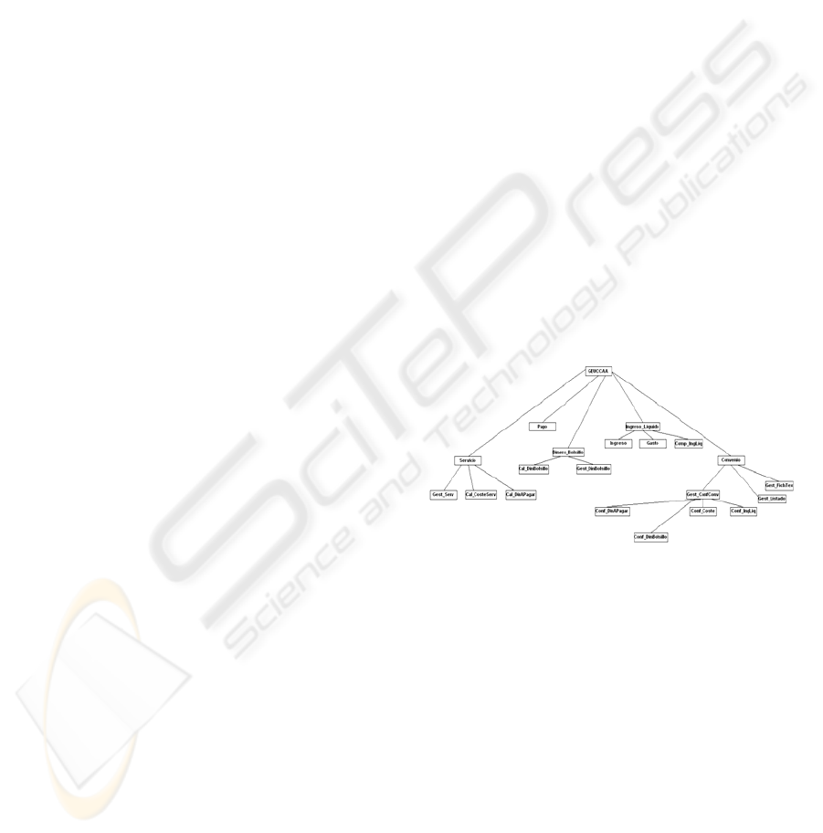
Definition of Feature Model. In Figure 1, we show
the feature model. We have also compiled a table
with the name, description and semantics of each
feature (although this does not appear in this article).
Figure 1: Feature model.
Definition of Requirement Object Model. We will
first show the object model and the part of the
dictionary referring to the name, description and
responsibilities for each requirement object.
AN IMPROVEMENT TO THE MIXED MDA-SOFTWARE FACTORY APPROACH: A REAL CASE
389
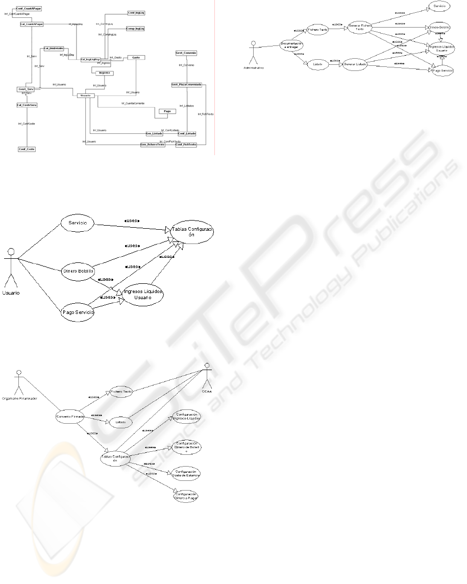
Figure 2: Requirement object model.
Definition of Use Case Model. We will examine the
different models.
Figure 3: Use case showing the relation between the user
and healthcare centre.
Figure 4: Use case for the form of agreement between the
financing organization and healthcare centre.
Figure 5: Use case showing the financial management
from the administrative agent’s point of view.
As we can see, any use case can be executed by
means of the constructed object model, and this
would therefore be validated. In this way, Chastek et
al.’s methodology (2001) would be completed for
our practical case to represent and validate the
requirements of this problem.
4.3.3 Obtaining the Initial Point in the
Mixed MDA-software Factory
Approach
As we mentioned above, we will obtain the product
line, framework and primitives of a specific use
language (in that order) from the products obtained
with the three requirement representation models.
Product line. As we indicated in subsection 4.2, we
define a product line as the information which needs
to be compiled for the development of a product or
product family. We can see that the product line in
our case would be established by the requirements
and dictionary of specific terms, represented by
means of both the feature and object models and
validated with use case diagrams.
Framework. As we indicated in subsection 4.2, we
will represent the framework using a design object
model, and we will start to define it from the
requirement object model.
a) Obtain the object names: we would obtain these
from the state objects and they would therefore
be design objects: Gest_Serv, Usuario, Pago,
Ingreso, Gasto, Gest_Convenio,
Gest_PlazaConveniada, Conf._Listado,
Conf_FichTexto, Conf_Coste,
Conf_CuantAPagar, Conf_DinBolsillo,
Conf_CompIngLiq and Conf_IngLiq. Obtain
the design object attributes: we will extract
these from the object description and the
responsibilities attributed to the object in the
object definition table.
Gest_Serv: financing organization, period
agreed, start date, end date, cost of the official
ICSOFT 2007 - International Conference on Software and Data Technologies
390
service, money payable, number of normal stay
days, number of forced stay days; payment
method, payment details and amount payable.
b) Methods: we will obtain these by means of the
behaviour objects with which the state object in
question is related and the requirement object
responsibilities. In this way, Gest_Serv;
Cal_DinBolsillo, Cal_CuantAPagar,
Cal_CosteServ are obtained from the behaviour
objects; and initiation, cessation and
modification of the service from the
responsibilities; Pago: it is possible to deduce
initiation, cessation and modification of
payment from the object responsibilities.
c) Relations between the objects: those existing
between the state objects of the requirement object
model will be taken but each will be typified in
accordance with those indicated for the design object
models according to the description and
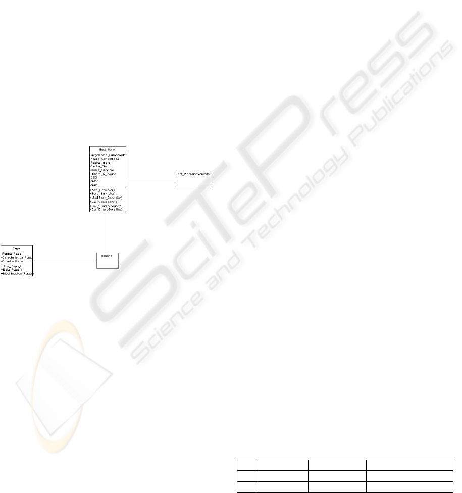
responsibilities. All the relations in the following
diagram are association ones (since there is a
semantic dependence between the classes).
Figure 2: Framework relating to the requirement objects
being studied: Gest_Serv and Pago
When the framework is obtained from the
requirement object model that we have designed, we
can see that we get quite close to GECAC’s design
object model (Muñoz, G., Granja, J.C., Sempere, C.,
2006). Once the automatic transformation has
finished, there is the opportunity to complete the
framework with elements that were not taken into
account or which were initially overlooked. This
transformation therefore enables a subsequent
adjustment once the result has been obtained,
matching it even further to the client’s requirements.
Primitives of a Specific Use Language. This
concerns finding a series of primitives which enable
the variability to be defined in the way that each
financing organization manages every financed
service. Our starting point for this will be the
dictionary of specific terms in which we must
complete these terms paying special attention to
those which define the variability. For this point, we
will define a series of subject matters which will
group the terms.
In our case, the subject matters to be developed
which are associated with the variability of our
problem are: LISTS, TEXT FILES, NET INCOME
(INVOICING PERIODICITY and SHARING OF
NET INCOME), POCKET MONEY, OFFICIAL
SERVICE COST and AGREEMENT (PERIOD OF
TIME WHEN ACTIVE and TYPES OF SERVICES
COVERED). We have developed all these terms
although they are not presented in this article.
We have ascertained that we can obtain information
for the creation of the specific use language from the
dictionary of specific terms and the requirement
objects.
4.4 Validation and Assessment of
Practical Study Case
The quality of the work carried out that we will
adopt is validated and quantified by comparing the
quality of the inputs with (first option) and without
(second option) our proposed mixed system. We will
assess each item below. Product line: using Chastek
et al.’s models and dictionary of specific terms
(2001), we see that the product line definition is
much more complete than if it were not used,
particularly when initial ignorance of the product
family is high. For this reason, we gave a score of 8
(out of 10) to the quality of the product line with
Method A, and a score of 4 to the quality with
Method B. Framework: as we can see in Muñoz et
al. (2006), the framework is complete, mainly due to
the high degree of knowledge that our work team
has of the subject; if we were to start with a problem
that we were unfamiliar with, the framework of
Option A would be much fuller and better suited to
reality than B. In the case concerning us, we gave
Option B a score of 9, and Option A scored 6.
Specific use language: this is a similar case to that of
the framework whereby the language is much better
defined and more complete using Option A than it is
with Option B (although the great difference arises
when we have no prior knowledge of the problem).
Table 1: Comparison.
Product line Framework Specific use language
A 8 9 8
B 4 6 5
AN IMPROVEMENT TO THE MIXED MDA-SOFTWARE FACTORY APPROACH: A REAL CASE
391

5 CONCLUSIONS AND FUTURE
WORK
As we have seen in the practical study case, it is
possible to create a system which enables us to
represent requirements in models and after
consecutive (more or less automatic) transformations
to generate code. In order to do so, advantage is
taken of the output products provided by Chastek et
al. (2001) and these are redirected to the inputs of
the mixed MDA-software factory model by means
of a series of transformations which we have
designed and presented in this article.
From the practical study case, we can deduce that
the application of our proposal is advantageous since
the result of the inputs on the mixed MDA-software
factory systems is more complete than when it is not
used (although the result is much better if there is
high prior ignorance of the family of programmes to
be developed).
We have detected certain negative aspects in terms
of this representational method: both the feature and
requirement object models are not UML models and
therefore the dictionary of specific terms (like the
other three models) has no repository for storing
them, and we could well use this as the basis for
mechanizing the adaptation transformations to the
mixed MDA-software factory model.
After an in-depth study, looking at the products and
documentation generated and the needs facing us,
we can conclude in terms of the transformation of
the requirement object model to the framework
(always aimed at possible automation) that obtaining
the design object names (i.e. the ones which
determine the framework) is direct, although those
relating to completing the attributes and the
messages associated to these objects is complicated
due to the need to extract the description information
in text format. We have seen how this requires the
analyst to complete the missing objects manually
and to deduce the object attributes and messages
from the object description and responsibilities.
With this solution, it would be possible to adjust the
transformations.
Regarding the generation of the specific domain
language, we have seen how the information relating
to the objects to be dealt with comes from the
dictionary of specific terms in which each concept
will be described (including those causing problem
variability). For an automatic generation of the
definition of the specific domain language, we
propose various modifications to the definition
tables for the term dictionary and to the definition
table for the requirement objects shown in the
previous point. With the proposed changes, greater
mechanization may be achieved.
5.1 Future Work
There are two different avenues open for future
research. The first would encompass completing the
requirement representation system with a study to
achieve greater automation of the creation of the
different models, conversion of non-UML models to
other more standardized ones, and the creation of a
repository to store the models, transformations and
dictionary. The second, meanwhile, would
encompass transformations with the definition of the
transformations proposed using a standard language
such as QVT. This work has been carried out under
project PP.2006.
REFERENCES
Aaen, I., Botcher, P., Mathiassen, L., 1997. The Software
Factory: Contributions and Illusions. In Proceedings
of the Twentieth Information Systems Research
Seminar in Scandinavia, Oslo, 1997.
Chastek, G., Donohoe, P., Kang, K.C., Thiel, S., 2001.
Product Line Analysis: A Practical Introduction.
Technical Report CMU/SEI-2001-TR-2001-001,
Software Engineering Institute (Carnegie Mellon),
Pittsburgh, PA 15213.
MDA (Model Driven Architecture). March 12, 2002.
http://www.omg.org/mda
Millar, J., Mukerji, J, 2003. MDA Guide Version 1.0.1.
Muñoz, G., Granja, J.C., Sempere, C., 2006. Sistema mixto
MDA – Factorías de Software: Un caso práctico.
CISTI 2006, Volume II, pág 503-518.
Muñoz, J., Pelechano, V., 2004. MDA a Debate. In I
Taller sobre Desarrollo de Software Dirigido por
Modelos, MDA y Aplicaciones (DSDM’04), pages
pp.1 – 12, 2004.
Muñoz, J., Pelechano, V., 2005. MDA vs Factorías de
Software. II Taller sobre Desarrollo de Software
Dirigido por Modelos, MDA y Aplicaciones (DSDM
2005)
ICSOFT 2007 - International Conference on Software and Data Technologies
392
