
A METHOD TO MODEL GUIDELINES FOR DEVELOPING
RAILWAY SAFETY-CRITICAL SYSTEMS WITH UML
+
D. D. Okalas Ossami,
+
J.-M. Mota,
∗
L. Thiry,
∗
J.-M. Perronne
∗
MIPS / Universit
´
e de Haute Alsace, ENSISA LUMIERE, 12 rue des Freres Lumi
`
ere
68093 Mulhouse Cedex, France
+
J.-L. Boulanger
+
HEUDIASYC / Universit
´
e de Technologie de Compi
`
egne, Centre de recherches de Royallieu
BP 20529, 60205 Compi
`
egne Cedex, France
G. Mariano
ESTAS / Institut National de Recherche sur les Transports et leur S
´
ecurit
´
e, 20 rue
´
Elis
´
ee Reclus
BP 317, 59666 Villeneuve d’Ascq, France
Keywords:
UML, safety-critical development, Certification, Development methodologies.
Abstract:
There are today an abundance of standards concerned with the development and certification of railway safety-
critical systems. They recommend the use of different techniques to describe system requirements and to
pursue safety strategies. One problem shared by standards is that they only prescribe what should be done or
use but they provide no guidance on how recommendations can be fulfilled. The purpose of this paper is to
investigate a methodology to model guidelines for building certifiable UML models that cater for the needs
and recommendations of railway standards. The paper will explore some of the major tasks that are typical of
development guidelines and will illustrate practical steps for achieving these tasks.
1 MOTIVATIONS
The will to increase the proportion of railway trans-
port has boosted in the recent years the modernization
of both software and hardware equipments in the rail-
way sector in Europe. Thus, old cabling based com-
munication and control systems are being replaced
with computer based software systems. These latter
systems are safety-critical, since defects may have se-
rious consequences, often loss of human lives or im-
portant economic interests. In this context, there are
strong requirements to obtain:
• An evidence of safety in system requirements
specifications;
• An approval of system requirements specifica-
tions by an independent supervising authority be-
fore deploying safety-critical systems.
So, the problem is that compelling evidence and
assessing safety are difficult, costly and time consum-
ing tasks.
Recently, the European Committee for Electrotech-
nical Standardisation (CENELEC) has elaborated a
number of standards (CENELEC, 1999; CENELEC,
2001; CENELEC, 1994; CENELEC, 1996a; CEN-
ELEC, 1996b) (cf. Figure 1) to be fulfilled when de-
veloping railway safety-critical systems. One prob-
lem shared by these standards is that they only pre-
scribe what should be done or use but they provide no
guidance on how recommendations can be fulfilled.
To build a good certifiable system specification, sound
development methodologies must be used. However,
the use of such methodologies for describing safety-
critical requirements within a language that offers a
broad scope of notations such as UML (OMG, ) is
not always easy or intuitive. The use of a flexible
modelling technique such as UML to develop safety-
critical systems may also help in reducing develop-
ment cost and time to market since UML is a defacto
standard used in industrial modelling. In addition,
an important number of designer are trained in UML
making less training necessary.
236
D. Okalas Ossami D., Mota J., Thiry L., Perronne J., Boulanger J. and Mariano G. (2007).
A METHOD TO MODEL GUIDELINES FOR DEVELOPING RAILWAY SAFETY-CRITICAL SYSTEMS WITH UML.
In Proceedings of the Second International Conference on Software and Data Technologies - SE, pages 236-243
DOI: 10.5220/0001338302360243
Copyright
c
SciTePress
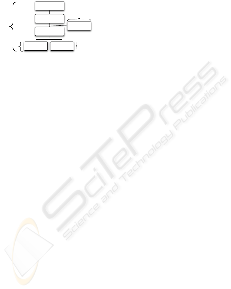
Hardware
Equipment
Complete Railway
Systems
Complete Signaling
Systems
SubSystems
Software
Equipment
EN 50 126
EN 50 129
EN 50 128
Communication
System
EN 50 159.1
EN 50 159.2
Figure 1: Scope and application areas of CENELEC Stan-
dards
The research presented in this paper is placed in
the big picture of this question. It extends our prior
work (Okalas Ossami et al., 2007) on the definition
of a methodology to model development guidelines
for building certifiable UML models that cater for
the needs and recommendations of railway standards
by attempting to investigate the applicability of that
methodology.
As a starting point of our methodology to model
guidelines for building certifiable UML models, we
select a subset of UML that we judge suitable for
safety development. This subset is analyzed and
safety-critical oriented guidelines for describing sys-
tems with concepts of that subset are elaborated.
Based on the works made on the transformation be-
tween UML and formal notations, we define a process
that describes how the selected subset can be used
to derive formal representations in notations like B
(Abrial, 1996) and FSP (Magee and Kramer, 2006)
to enable formal verification of static and dynamic
properties, respectively. Finally, we define a certifica-
tion methodology describing how models constructed
with concepts of the selected subset can be certified.
This work is carried out in the context of an inter-
regional project (in France), including the French rail-
way company (SNCF). This project started in novem-
ber 2006 and hence the current paper only describes
the main ideas and preliminary results.
The paper is organised as follows. Section 2 de-
scribes our methodology for elaborating development
and certification guidelines of railway safety-critical
systems with UML. Section 3 introduces the case
study used to illustrated ideas presented in the pa-
per. Section 4 illustrates the application the proposed
methodology on the case study. Section 5 concludes
and introduces some future works.
2 A METHOD TO MODEL
GUIDELINES FOR
DEVELOPING
SAFETY-CRITICAL SYSTEMS
WITH UML
Fig. 2 presents an overview of the context of our
study. We advocate to perform multiple tasks aim-
ing at producing guidelines to help both (1) design-
ers in developing railway safety-critical systems with
UML and, (2) supervising authorities in certifying
these systems. The significance of envisaged tasks is
summarized below.
Selecting a subset of UML. In this task, a sub-
set of UML notation is chosen as standard for the
safety-critical mainstream development. One reason
for this is that not all kinds of diagrams and concepts
are needed in order to describe a system or a process.
Another reason is a normative one. It is strongly pro-
hibited by standards of CENELEC to ”blindly” use
all the concepts of a language or a method, but only
some of its concepts judged safe to describe safety-
critical functions. To clarify, the selection of a sub-
set of UML is not about selecting some UML con-
cepts in order to extend them for particular objectives,
nor is the selection of a subset of UML about redefin-
ing a particular semantics for selected concepts. The
key objective of the selection of a subset of UML is
precisely to isolate concepts with well-defined seman-
tics that are suitable for developing safety-critical sys-
tems. This clearly means that any concept with am-
biguous semantics are systematically removed from
the selected subset.
Modelling development guidelines. The chosen
subset of UML is carefully analysed to produce an
appropriate formal and well-defined guidance on how
and in which situations concepts can be used. The use
of some UML concepts within a given real develop-
ment is not always intuitive or easy. Thus, any support
to aid safe systems development would be useful. In
particular, it would be desirable to consider restricted
and simplified concepts to keep mechanical analysis
that is necessary for some of the more subtle safety
requirements feasible.
Assigning a formal semantic. Since validation
and verification activities are not directly accessible
in UML, a formal semantic is assigned to each con-
cept of the chosen subset notation in terms of transla-
tion rules to target formal notations with well-defined
syntax and semantics. The aim is to perform con-
sistency proofs and verify the desired safety proper-
ties as highly recommended by Standards for software
A METHOD TO MODEL GUIDELINES FOR DEVELOPING RAILWAY SAFETY-CRITICAL SYSTEMS WITH UML
237
with high safety integrity level.
In the case of this study, we advocate to use sev-
eral formal techniques, when performing proving.
The reason for this is that no single formal notation
can address all the topics cited above because dif-
ferent notations and supporting tools have different
strengths in different areas. Another reason is that
CENELEC EN 50 128 recommends the use of mul-
tiple verification techniques and tools in order to pro-
vide independent verification. In our study, we use:
• The B method (Abrial, 1996), one of the formal
notations supported by formal analysis tools. One of
the tools supporting it, atelierB (ClearSy, 2002) can
be used, when performing the proving of static prop-
erties (invariants, pre- and post-conditions, etc.);
• The Finite State Processes (FSPs) (Magee and
Kramer, 2006) when performing the proving of dy-
namic properties.
To get a B specification (resp. FSP specification)
from a UML model, we needs to perform a translation
from UML into B (resp. FSP). For this purpose, our
goal is to reuse the efforts that have been out in the
production of UML to B and UML to FSP translation
rules rather than to define a new ones. Note that the
actual translation from UML to B and UML to FSP is
not standardized. To be used in a certification frame-
work, they must be redefined in an international rec-
ognized and standardized framework such as Model
Driven Engineering (MDE).
Modelling certification guidelines. This task
aims at giving some hints on how supervising author-
ities may attest both that the right system has been
built (validation) and that the system has been built
right (verification). This is a long term objective and
is let out the scope of this paper. The illustration of
how all these tasks is given in the next sections.
Railway
Standards
(CENELEC)
Selecting
a subset of UML
Assigning
a formal semantic
to concepts
of the selected
subset
Modelling certification
guidelines of systems
developed with the
selected subset
Modelling
development guidelines
with the selected
subset of UML
Figure 2: Tasks specific towards preparing development and
certification guidelines for rail way safety-critical systems
with UML
3 A SMALL CASE STUDY
For illustrating ideas developed in the paper, we
consider the simplified generalized roadrail crossing
(GRC) example (see Fig.3 (Jansen and Schnieder,
2000)). The general requirements are to produce a
computerized system to control trains and a gate at a
railroad crossing which lies in a region of interest R.
Trains travel in one direction through R. Sensors in-
dicate when a train enters or exits the region R. For
space and clarity reasons, we restrict ourselves to el-
ements which are relevant to illustrate our approach.
More details can be found in (Jansen and Schnieder,
2000). The Train may be in five states: 0, 1, 2, 3
and 4 see Fig. 3. The state of the train is determined
by information provided by sensors positioned on the
track and by a clock. When a train leaves a region and
enters another one, a signal is sent to a system con-
troller which reacts by sending appropriate signals to
the gate. The gate also react by closing and opening.
The system must be safe: the gate must be down when
the train reaches state on.
We will describe the development of the system step
by step, starting with a class diagram which identifies
some important entities. Note that we only focus on
static aspects. Dynamic aspects such as operations,
event are out of the scope of this paper.
4
R
Gate
20 1
Sensor Sensor
3
Figure 3: The generalized railroad crossing.
4 A PRACTICAL VIEW OF THE
METHOD
4.1 Selecting a Subset of UML
The first task of our method is to fix a subset of UML
notation to be used in safety modeling. In CEN-
ELEC EN 50 128 it is recommended to produce a
precise specification of system requirements, which
ideally consists of a description of system functional
requirements, operational scenarios, system architec-
ture (structure) and behavior.
ICSOFT 2007 - International Conference on Software and Data Technologies
238
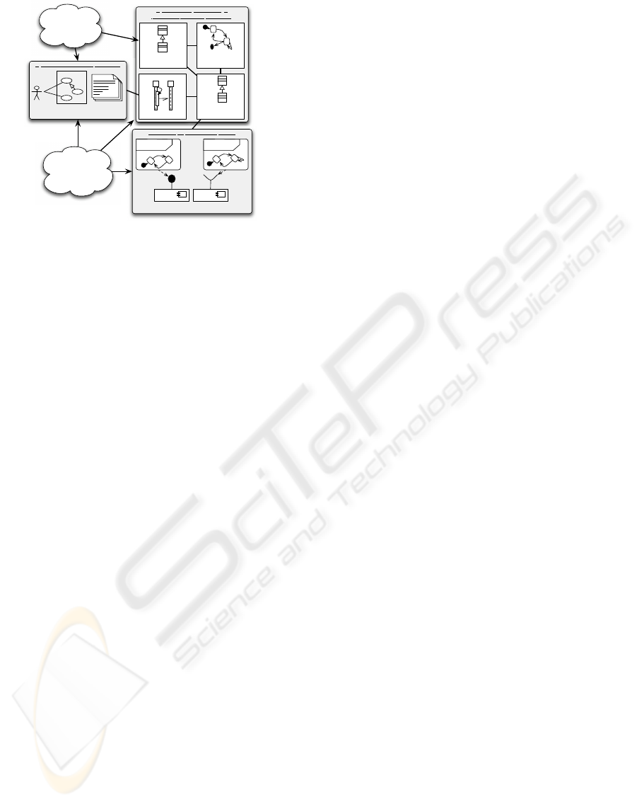
System Functional Requirements
System
Use case
diagram
Use case
specification
System Analsys and Design
(Behaviour, Scenario, Structure)
Analysis
Class diagram
Sequence diagram
StateMachine
diagram
informal
system
requirements
Execution (Implementation) Model
sm {protocol}
sm {protocol}
Component diagram
Design
Class diagram
Requirements
and constraints
coming from
safety analysis
activities
Figure 4: Our selected subset of UML
To deal with these different kinds of descriptions
we advocate to use diagrams shown in Fig 4. In this
figure, Use case diagram and widely accepted texts
templates are used to capture system functions (func-
tional requirements) and their safety requirements.
Use cases are then mapped unto Sequence diagrams
to model operational scenarios. They express inter-
actions in form of time-ordered messages exchanged
between instances of classes specified in the corre-
sponding Class diagram. The Class diagram is con-
structed to model the structure of the system. A State
machine is drawn for objects of classes having a state-
dependent behavior. This corresponds to behavioral
description of the system. Finally, in order to en-
able a qualitative analysis, responsibilities and oper-
ations identified in sequence diagrams are assigned to
classes to form design classes, from which one can
derive an executable model. This model gives a feed-
back about consequences of failures and their corre-
lation with the risk analysis that has been constructed
any where.
The executable model is generally structured by
means of interacting components together with their
interfaces. For each interface, a Protocol State Ma-
chines (PSMs) is drawn. It shows the permissible se-
quences of method calls (the protocol) on an object,
but not how the object will react to each method call.
4.2 Modelling Development Guidelines
An essential issue in order to achieve a successful
development of a safety-critical system is to assist
developers more intensively in the software develop-
ment process throughout the whole development life
cycle. The key challenge for this task is to prepare
appropriate guidelines on how chosen development
techniques and methods can be best used. This sec-
tion illustrates kinds of guidelines on developing an
UML model from system requirements. Due to space
restrictions, we restrict ourselves on giving general
guidelines for constructing use case diagrams.
General guidelines for constructing use case di-
agrams:
A use case diagram is a graphical representation
of goal-oriented interactions between external actors
and the software. Actors may be a class of users, other
systems or roles users can play in order to interact
with the system. They initiate use cases to achieve
particular goals. A use case describes a sequence of
interactions between actors and the software neces-
sary to deliver the service that satisfies a goal. A
use case combines sequences that achieve the goal,
as well as alternative sequences that may achieve the
goal and those that may lead to failures. Thus, a use
case diagram captures ”who (actor) does what (inter-
action) with the system under development, for what
purpose (goal)”. The construction of a use case dia-
gram can be done by a development process made up
of the following steps:
• Identify the set of all the different actors of the
system to be constructed;
• Identify roles relevant to the system that each ac-
tor plays;
• Identify for each role, significant goals each actor
has and that the system will support. That is, use
cases have to be associated to goals;
• Create actors and a use case for each goal;
• Realize a precise description each use case, fol-
lowing adapted Jacobson’s original style of Use
Case description template (Jacobson, 1992). One
instance of this template is given in Fig. 5;
• Review and validate the created use case diagram
with respect to system requirements.
Note that in the first and second items of the pro-
posed guidelines, the terms ”role” and ”goal” are in-
formal issues and do not necessarily imply any tech-
nical definition. They are issued here to help identi-
fying relevant use cases. The way in which they are
specified depends on specifier’s or user’s intentions.
A METHOD TO MODEL GUIDELINES FOR DEVELOPING RAILWAY SAFETY-CRITICAL SYSTEMS WITH UML
239
Use Case
request to close the bar of the gate
Description
This use case models a request to close the bar
of the gate in reaction of signals sent by sensors
when a train enters the region of interest.
Source
General system description (section 3).
Actors
Controller, Gate
Precondition
1. the signal enter must be first sent by the Sen-
sor
2. the bar must not be already closed
Steps
IF
the sent signal is ”enter” and
the bar is not already closed and
THEN
1. treats the signal ;
2. send the ”close” signal ;
ELSE
do nothing
Postcondition
The Gate must initiate closing the bar.
Alternative steps
[optional]
1. The Controller receives the enter signal from
Sensor.
2. The Controller notifies the train to apply the
emergencybrakesdueto a danger situation (i.e.,
person or car on the crossing, gate out of ser-
vice, etc.).
Failure
Description
The gate may initiate
opening instead to initi-
ate closing the bar when
receiving the close sig-
nal
Cause
a). Sensors may report
exiting while the train is
entering
b). Sensor entry sig-
nal may be wrongly
processed by the Con-
troller and decided as
exit.
Postcondition
The train must be
stopped before it
reaches the unprotected
level crossing.
Figure 5: Description of the use case ”request to close the
bar of the gate”.
The case study:
For illustration, let’s consider system requirements
given in section 3. So, following guidelines enumer-
ated above the use case diagram of Fig. 6 can be con-
structed. It clearly shows main actors and use cases
of the GRC. Note that due to space restrictions, de-
tails about the identification of actors, roles and goal
are omitted here in order to be synthetic as possible.
Having specified actors and associated use cases, we
can go straightforward to realize precise descriptions
of use cases. One example of such description is pre-
sented in Fig. 5. It shows a so-called ”precise de-
scription” of the use case ”request to close the bar of
the gate” according to Jacobson’s like template. This
use case is performed by the system controller when
a train enters the crossing.
detect exiting
trains
detect
entering trains
Sensor
requests to
open the bar
of gate
increases the
number of
trains
decreases the
number of
trains
requests to
close the bar
of gate
Controller
<<includes>>
<<includes>>
opens the bar
closes the bar
<<includes>>
<<includes>>
<<includes>>
GRC-System
Gate
<<includes>>
Figure 6: Use case diagram of the generalized railroad
crossing.
B Metamodel UML Metamodel
FSP Metamodel
UML2B
Mapping rules
UML2FSP
Mapping rules
B Metamodel
UML Metamodel
FSP MetamodelTransformation Transformation
<<conforms to>>
<<conforms to>>
<<conforms to>>
<<conforms to>>
<<conforms to>>
Figure 7: Concept space for instantiation of the MDE ap-
proach with UML, B and FSP formalisms.
Validation. The process includes validation checks to
ensure that no requirement is missed when going from
one step to the next or that no referenced requirement
is introduced in the use case description. To achieve
this, one must verify that the source indicated in the
description of each use case effectively contains the
described functionality.
4.3 Defining Rules for Translating
Concepts of the Subset into a
Semantic Domain
The transformation of a UML model into a seman-
tic domain allows that properties, especially safety-
properties can be analysed in a precise manner. In this
study, we will investigate the use of UML to B trans-
formation rules (Laleau and Polack, 2001; Marcano
and Levy, 2002; Meyer and Souqui
`
eres, 1999; Snook
et al., 2003) (Resp. UML to FSP rules (Beeck, 2001;
Yeung et al., 2005)) within the MDE approach. In this
approach, models are seen as key concepts of the de-
velopment. That is, UML models are developed and
transformed into one or more specific models targeted
at specific languages and environments. Thus, trans-
formation together with models are central to MDE.
One important issue of the MDE is that model trans-
formation refers to meta-models of the source and tar-
get languages. Fig. 7 shows a concept space for in-
stantiation of the MDE approach, showing UML, B
and FSP formalisms.
4.3.1 UML to B transformation
To illustrate this point, let’s assume the class diagram
of Fig. 8. It shows the main entities of the GRC-
system: Controller, Sensor and Gate. Each object of
the class Controller is linked to one or more object of
the class Sensor. An object of Controller refers to a
single object of the class Gate. The meaning of this
is that a gate is only controlled by a single controller.
Note that others entities like trains, track, etc. are not
taken into account here in order to keep the diagram
as simple as possible.
ICSOFT 2007 - International Conference on Software and Data Technologies
240
+numTrack : int
Sensor
+incrTrains()
+decrTrains()
+openBar()
+closeBar()
+enter(t : int )
+leave(t : int)
+nbTrains : int
Controller
+close()
+open()
Gate
*
1
1
1
Figure 8: Class Diagram of the generalized railroad cross-
ing.
The class Gate provides two methods, open and
close for opening and closing the bar, respectively.
The class Controller is characterized by the variable
nbTrains of type integer. It stores the number of trains
currently in the region of interest. The controller pro-
vides six methods:
• incrTrains() and decrTrains() to increase and de-
crease nbTrains;
• openBar() and closeBar() to request opening and
closing the bar of the gate;
• enter(t : int) and leave(t : int) to process signals
(from Sensors) indicating an entering and exiting
train. These two methods have each an integer
parameter t that denotes the number of the track
on which the train is entering or leaving.
The controller must always know from which sen-
sor a signal has been sent. This allows to systemati-
cally determine on which track a train is entering or
leaving. To achieve this purpose, the controller refers
to the variable numTrack of type integer defined in the
class Sensor.
Figure 9 represents the skeletons of the B spec-
ification of the class Controller obtained by an au-
tomatic translation of the UML specification (cf.
Fig. 8). Note that the actual translation from UML
diagrams into B is not of interest for the study under-
taken in this paper. Of interest are the formal concepts
coming with the B language and whether and how it
is applicable in our study.
MACHINE
Types
SETS
OBJECTS
CONSTANTS
..., CONTROLLER
PROPERTIES
...
CONTROLLER ⊆OBJECTS
END
MACHINE
Controller
SEES
Types
...
VARIABLES
controller, controller sensor,
controller
gate, nbTrains
INVARIANT
controller ⊆ CONTROLLER ∧
controller
sensor ∈ controller → sensor ∧
controller
gate ∈ controller ։ gate ∧
nbTrains ∈ controller → NAT
INITIALISATION
controller :=
/
0 || controller sensor :=
/
0 ||
controller
gate :=
/
0 || nbTrains :=
/
0
OPERATIONS
incrTrains(oo) = ...
PRE
oo ∈ controller
THEN
skip
END ;
...
END
Figure 9: Skeletons of the B specification derived from the
class diagram of Fig. 8.
Interested reader can find some proposals on UML
and B transformation in (Meyer and Souqui
`
eres,
1999) (Resp. UML to FSP rules (Perronne et al.,
2006)). However, we can summarize the general in-
tuition of the UML to B transformation as follows:
• For each classifier with name Class an abstract
machine having the same is constructed. The
modelling of this machine includes a set CLASS
and a variable class⊆ CLASS denoting the set of
possible and existing instances of Class, respec-
tively;
• Attributes attr: attrType of Class and associations
are modeled as functions from class to attrType
or associated class instances. The type of the
functions reflects the multiplicity (multi-values or
mono-valued attributes) of the attribute or the car-
dinalities and participation of the class for associ-
ations;
• Operations are derived as B operations mirroring
the syntactical structure of the associated state di-
agram if such a diagram exists. Otherwise, the
body of operations is modelled as skip. Opera-
tion parameters are typed and further constrained
in the operation precondition (
PRE
clause). For
each operation there is an additional parameter oo
of type class that represents the object that exe-
cutes the operation.
In addition to machines representing classes, we
introduce a special machine Types, which declares a
number of shared sets or types. The others classes are
derived in a similar way.
A METHOD TO MODEL GUIDELINES FOR DEVELOPING RAILWAY SAFETY-CRITICAL SYSTEMS WITH UML
241

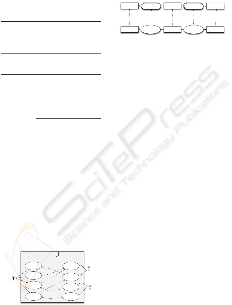
4.3.2 UML to FSP transformation
Process Algebra like FSP is suitable for describing
discrete behaviour of concurrent and communicating
systems. A system is described in FSP by the parallel
composition of processes (see k, Fig 10). A process
is an entity that executes an action and then behaves
like another process (see action prefix →); the choice
(|) make it possible the composition of the various
actions a process can execute. A process can be ”in-
stantiated” from another process (see process labeling
:) and renaming make it possible the synchroniza-
tion of two or more processes (see /). The main
components of the UML notation can be described
with these constructs. A class and its statechart can
be transformed to processes; operations and events
correspond to actions. Object and communication
diagrams can be obtained using parallel composition,
process labelling and renaming. Of course, these
transformation rules of UML models into FSP require
many constraints, as for example the suppress of
hierarchy (e.g. macro states in statecharts); these
restrictions are then used to identify the subset of
UML that can be formalized and validated.
The case study. Fig. 10 represents the transformation
of the UML model (Fig. 8) into FSP. In this example,
the processes YYY correspond to the various states of
the controller. XXO means, for instance, that a train
is in section 1 and sections 2 and 3 are free; tij repre-
sents the movement of a train from section i to section
j (the events entry and t01, resp. exit and t34, corre-
spond to the operation incTrains, resp. decTrains,
Fig. 8).
Gate = (close → open → Gate).
Controller = OOO,
OOO = (entry → XOO),
XOO = (t12 → OXO),
OXO = (t23 → OOX | t01 → XXO),
OOX = (exit → OOO | t01 → XOX),
XXO = (t23 → XOX),
XOX = (t34 → XOO | t12 → OXX),
OXX = (t01 → XXX | t24 → OXO),
XXX = (t34 → XXO).
k Sys = (g : Gate k c : Controller)/
{c.entry/g.close,c.exit/g.open}.
Figure 10: FSP transformation of the UML model (4.3.1).
Our works have shown how FSP models can be
automatically generated. A. Rasse (Rasse et al., 2005)
has used MetaEdit+, a tool of the MDE community,
configured with an UML metamodel, a FSP meta-
model and the transformation rules described below
(and illustrated in Fig. 7) to validate critical systems
modeled with UML (conforms to the metamodel cho-
sen). The tool LTSA (LTS, ), proposed by Magee and
Kramer, makes it possible the checking of properties
such as vivacity (e.g. no deadlock) or security (e.g.
the gate is kept close until a train is in section 1, 2 or
3; it is open otherwise). The model checking is done
either in a systematic way by the use of model check-
ing algorithms, either by simulation (or test case). For
instance, the automata of Fig. 11 is obtained by the
compilation of the FSP model and can be used to fol-
low step by step the behavior of the whole system.
7
c.entry c.t12
1 2 5 63 4
c.t01 c.t23 c.t12 c.t01
c.t23
c.t01
c.t34
c.t24c.t34
c.exit
Sys
0
Figure 11: Behavior of the whole system Controller + Gate.
4.4 Modelling Certification Guidelines
Certification is a procedure by which a supervision
Authority gives written assurance that a product, pro-
cess, or service conforms to specified requirements
(Standards). In the railway technology, certification
mainly focuses on safety, in which the requirements
are based on safety objectives of the system. In this
setting, the research on UML and software certifica-
tion should concentrate on providing methodological
support to help supervision authorities in answering
the following two questions:
• Did designers build the right UML system ?
• Did designers build the UML system right ?
The first question deals with validation issues.
Since the process includes validation checks at each
stage of the development, the answer to this question
consists in verifying that each validation check has
been performed successfully.
The second question is a more complex one. It deals
with verification issues. It also involves providing
means that may help supervising authorities in ap-
proving the following verifications:
• The verification that related UML diagrams of
the same abstraction are consistent each with the
other, provided that each diagrams is by itself con-
sistent;
• The verification that corresponding diagrams in
different abstraction levels do not model contra-
dictory requirements;
• The verification that formal proofs of the UML
specification has been performed successfully;
• The verification that the UML model and its for-
mal counter part do not contradict each other.
ICSOFT 2007 - International Conference on Software and Data Technologies
242

The way in which supervising authorities will be
helped to approve these verification is still an open
issue.
5 CONCLUSION AND FUTURE
WORK
UML is a flexible and powerful technique for cap-
turing system requirements. However, like any tech-
nique, there are several challenges in modeling and
scaling practical promising guidelines to assist the de-
velopment and the certification of safety-critical sys-
tems that cater for the needs and recommendations
of safety standards. UML is currently lacking in this
question. In this extended abstract, we have sketched
main tasks specific towards preparing development
and certification for railway safety-critical systems
with UML. This allows helping both:
• Developers in increasing the confidence in the
system developments correctness while reducing
the time of the development and the costs for the
systems certification;
• Supervision authorities in approving both that: (1)
Developers did build the right UML system and
(2) Developers did build the UML system right.
The identification of main tasks to model devel-
opment and certification guidelines is important but
is only the first step. The careful study of key con-
cepts of each of these tasks is a next important steps
or perhaps even more so. This clearly means that for
future work, we have to go one step straightforward
to detail each of the tasks presented in section 3.
REFERENCES
LTSA - Labelled Transition System Analyser.
http://www.doc.ic.ac.uk/ltsa/.
Abrial, J. (1996). The B Book: Assigning Programs to
Meanings. Cambridge University Press. ISBN 0-521-
49619-5.
Beeck, M. V. D. (2001). Formalization of UML Statecharts.
In UML’01, volume 2185, pages 406–421. Springer.
CENELEC (1994). EN 50129: Railway applications -
Safety related electronic systems for signaling.
CENELEC (1996a). EN 50159.1: Railway applications
- Communication, signaling and processing systems.
Part I: Safety related communication in closed trans-
mission systems.
CENELEC (1996b). EN 50159.2: Railway applications
- Communication, signaling and processing systems.
Part I: Safety related communication in open trans-
mission systems.
CENELEC (1999). EN 50126: Railway applications -
The specification and demonstration of dependabil-
ity, reliability, availability, maintainability and safety
(RAMS).
CENELEC (2001). EN 50128: Railway applications - Soft-
ware for railway control and protection systems.
ClearSy (2002). B reference manual V1.8.5.
Jacobson, I. (1992). Object-Oriented Software Engineer-
ing: A Use Case Driven Approach. Addison-Wesley.
ISBN 0201544350.
Jansen, L. and Schnieder, E. (2000). Traffic control sys-
tem case study: Problem description and a note on
domain-based software specification. Technical re-
port, Colorado State University.
Laleau, R. and Polack, F. (2001). A Rigorous Metamodel
for UML Static Conceptual Modelling of Information
Systems. In Advanced Information Systems Engineer-
ing, CAiSE’01, volume 2068 of LNCS, pages 402–
416. Springer.
Magee, J. and Kramer, J. (2006). Concurrency - State Mod-
els and Java Programming. Wiley.
Marcano, R. and Levy, N. (2002). Using B formal specifica-
tions for analysis and verification of UML/OCL mod-
els. In Workshop on Consistency Problems in UML-
based Software Development, pages 91–105.
Meyer, E. and Souqui
`
eres, J. (1999). A systematic ap-
proach to transform OMT diagrams to a B specifica-
tion. World Congress on Formal Methods in the De-
velopment of Computing Systems, FM’99.
Okalas Ossami, D., Mota, J.-M., Thiry, L., Perronne, J.-
M., Boulanger, J.-L., and Mariano, G. (2007). A
method to model guidelines for developing railway
safety-critical systems with UML. In the 7th Interna-
tional SPICE Conference (Software Process Improve-
ment and Capability dEtermination), Seoul (Korea).
OMG. Unified Modeling Language Specification. The
Object Management Group (OMG). Available at:
http://www.omg.org.
Perronne, J.-M., Rasse, A., Thiry, L., and Thirion, B.
(2006). A modeling framework for complex behav-
ior modeling and integration. International Journal on
Computer Science and Information Systems, IADIS, 1.
Rasse, A., Perronne, J.-M., Muller, P.-A., and Thirion,
B. (2005). Using process algebra to validate behav-
ioral aspects of object-oriented models. In Model de-
sign and Validation Workshop, MODEVA’05, LNCS.
Springer.
Snook, C., Butler, M., and Oliver, I. (2003). Towards a
UML profile for UML-B. Technical report, DSSE-
TR-2003-3, University of Southampton.
Yeung, W., Leung, K., Wang, J., and Dong, W. (2005). Im-
provements towards formalizing UML state diagrams
in CSP. In Asia-Pacific Software Engineering Confer-
ence, APSEC’05. IEEE Computer Society.
A METHOD TO MODEL GUIDELINES FOR DEVELOPING RAILWAY SAFETY-CRITICAL SYSTEMS WITH UML
243
