
COMPONENT BASED METHODOLOGY FOR QOS-AWARE
NETWORK DESIGN
Cedric Teyssié, David Espès and Zoubir Mammeri
IRIT Laboratory – Paul Sabatier University, Toulouse, France
Keywords: Quality of Service, QoS-aware Network, Component, UML, specification.
Abstract: New services (such as VoIP) and their quality requirements have dramatically increased the complexity of
the underlying networks. Quality of Service support is a challenge for next generation networks. Design
methods and modeling languages can help reduce the complexity of the integration of QoS. UML is
successfully used in several domains. In this paper, we propose a QoS component oriented methodology
based on UML. This methodology reduces network-design complexity by separating design considerations
into functional and non-functional parts. It also provides a design cycle and proposes abstraction means
where QoS is integrated. As UML is not adapted for modeling non-functional elements, we combine UML
strengths and a QoS specification language (QSL).
1 INTRODUCTION
Networks become more and more complex with
numerous services and multiple QoS requirements.
The design methodology must help reducing this
complexity. However, the development of QoS
networks implies reducing networks complexity but
also dealing with functional and non-functional
aspects of the system. QoS aspects are often referred
as non-functional characteristics. The use of UML
(OMG, 2003-1) helps reducing this complexity but it
is not well adapted for modeling non-functional
aspects. We develop QSL (QoS Specification
Language) to capture, represent and handle QoS
elements in networks. QSL can be combined with
several modeling languages such as SDL
(Specification and Description Language) and UML.
Even if UML combined with QSL helps
modeling QoS networks, it does not necessarily
cover all development tasks. It does not deal with
complexity reduction and does not help capturing
system properties and services. We present in this
paper a QoS component based methodology for
QoS-aware network design. This methodology aims
to reduce complexity with QoS components, to deal
with service/equipments considerations, to allow
validation of models and therefore to help
maintaining a high quality development.
This paper is organized as follows. Section 2
deals with related work. Section 3 briefly presents
QSL. Section 4 discusses our approach and
extensions to UML. Section 5 presents our
methodology and section 6 concludes the paper.
2 RELATED WORKS
The OMG issued two UML profiles to integrate
QoS: “Schedulability, Performance and Time
Profile” (OMG, 2003-2) and “UML Profile for
Modeling Quality of Service and Fault Tolerance
Characteristics and Mechanisms” (OMG, 2004-1).
However, the solutions proposed do not take into
account QoS network specific elements such as QoS
contracts and some elements are not precisely
defined.
Some work proposed to integrate QoS aspects in
middleware such as CORBA (OMG, 2004-2). In
QoS Modeling Language (QML) (Frølund and
Koistinen, 1998), QoS elements are integrated in the
system interfaces specified in IDL (Interface
Definition Language). UML is used only for
functional parts of the system. Component QML
(Aagendal, 2001) is an extension of QML. It adds
component notion. A third approach is QuO (Quality
Objects) (Zinky, Baken and Schantz, 1997). This
approach proposed QDL, a QoS Description
Language extending IDL and that takes also into
account QoS contracts. We believe these approaches
190
Teyssié C., Espès D. and Mammeri Z. (2007).
COMPONENT BASED METHODOLOGY FOR QOS-AWARE NETWORK DESIGN.
In Proceedings of the Second International Conference on Software and Data Technologies - SE, pages 190-197
DOI: 10.5220/0001338501900197
Copyright
c
SciTePress

are not well suited for network design as they are
platform dependant.
Other approaches such as HQML (Gu,
Wichadakul and Narhstedt, 2001) are not specialized
in network design with UML. As a result, the
integration of these approaches into UML models is
a challenge.
Our methodology relies on a QoS specification
language (§3) allowing QoS capture and on a UML
design for network components capture.
3 QSL: QOS SPECIFICATION
LANGUAGE
Our methodology uses a QoS language (QSL)
(Teyssié, 2005), to solve two main problems: QoS
specification and specification of network elements
QoS. This QoS language focuses on QoS
representation. It is used for specification of QoS
structure elements that are used in the design process
and for QoS handling. QSL is composed of two
levels: QoS Structure Definition and QoS Handling.
QoS Structure Definition level focuses on the
QoS capture. It defines the components of a
QoS to build a QoS model. This model is used
as a QoS reference for QoS handling. Only
QoS elements belonging to the QoS model can
be used in the design process.
QoS Handling level deals with QoS elements
such as QoS constraints and valuation of QoS
elements. This sub-layer is based on the
instantiation of the QoS elements from the
QoS model.
QoS definition may use graphical or textual
representation for QoS elements. For QoS
validation, these representations are converted into
vectors. As (ISO/ITU, 1997) and (Mammeri, 2004),
QSL is based on vector notion. A QoS element is
represented as the vector of its constitutive elements.
A QoS may inherit from another defined QoS or
may be composed from QoS characteristics. A QoS
characteristic represents an autonomous fraction of a
QoS. It focuses on a particular domain (as time). It is
composed either by QoS aspects or inherits from
another QoS characteristic. A QoS aspect represents
a single view of a QoS characteristic. For example,
for time-domain QoS characteristics, a QoS aspect
may be maximum delay. A QoS aspect may inherit
from another QoS aspect. In other case, a QoS
aspect belongs to a type. It indicates on which aspect
of a QoS characteristic the aspect focuses. A QoS
aspect must be associated with a value type that
indicates the container type for the aspect values. It
is followed by a unit label and comparison or
combination properties. The combination properties
specify how to combine several aspects in one
global aspect. As in (Wang and Crowsoft, 1996),
QSL defines three QoS metric types: additive (e.g.
transfer delay elements), multiplicative (e.g.
reliability elements) and concave (e.g. bit rate
elements). The comparison of properties focuses on
the manner of comparing two aspects. In some
cases, a higher value denotes a higher quality.
However, sometimes, as for transmissions times, a
lower value denotes a higher QoS.
QoS Handling language allows six operation
types: QoS instantiation of a QoS belonging to the
QoS model, assignment of values to QoS, combining
QoS, comparing QoS, QoS constraint specification
and QoS contract specification.
4 QSL ADAPTATION LAYER
QSL cannot be used as is in UML. In this section we
propose UML extensions to integrate QSL
specifications. To keep backward compatibility with
existing UML models, we choose UML light
extension mechanism. This adaptation layer deals
with UML integration in two ways: QoS
components definition and QoS components
integration in UML models.
4.1 QoS Components
Network elements are captured in QoS components.
To reduce network design complexity, network
considerations are separated in a horizontal
structure: functional parts, architectural parts and
QoS.
The functional part concerns only elements that
participate in the communication. In this sense,
services (like forwarding services) deployed in
single equipment or across the entire network are to
be captured in the same way.
A single functionality may be deployed in a wide
range of equipments, each one with different
capabilities. The architectural part captures the
network architecture to specify equipments
capabilities and service partition on these
equipments.
The QoS part captures the network QoS without
architectural or functional considerations. Thus,
changes in this category may change functional
and/or architectural specification.
COMPONENT BASED METHODOLOGY FOR QOS-AWARE NETWORK DESIGN
191
As this distribution does not take into account
static and dynamic aspects of the network. We
propose to separate static and dynamic aspects for
the functional and architectural parts.
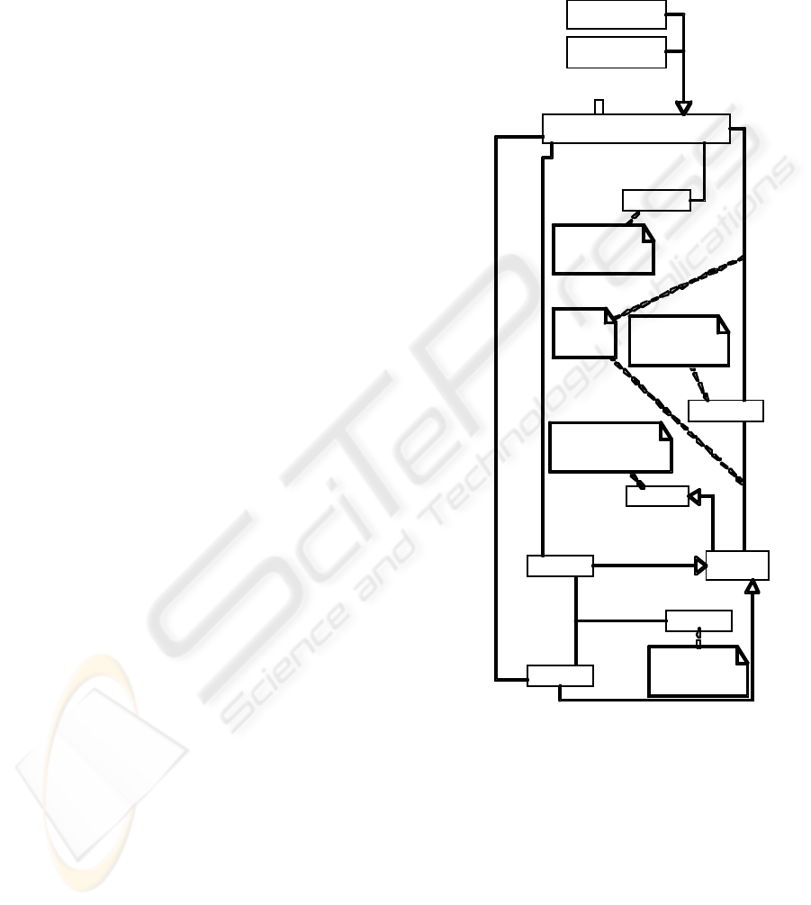
A QoS component (Figure 1) is somewhat
similar to the service notion in the General Resource
Model (GRM) of (OMG, 2003-2 and OMG,
2004-1). We define this
QoS_Component as an
abstract one. Two classes inherit from
QoS_Component: Service and Physical
_component
. These classes are to be instantiated
before being used. A component may be handled as
a black box that offers (or requires) a particular QoS
through its interfaces to other components.
The QoS may be directly associated with the
QoS component context. This QoS (
QoS_Property)
represents the qualitative properties of the whole
component that do not depend on its relationships.
Several components may offer or require
connections to other components but with a
differentiated QoS. It implies that QoS also depends
on component relationships. We define an access
point (AP) as an interface (inherits from UML
interfaces) between two QoS components. These AP
are only logical ones. They allow sharing several
connections from a single interface and their usage
does not limit the hardware (or software)
development. AP class is abstract and splits into two
inherited classes following the Client/Server
paradigm:
Client_AP and Server_AP. Components
communication takes place between these APs:
A client AP is used by a component to call
another component. If both components are
services, a
Client_AP is used by the client
component to call the service of the other
component.
A server AP is used as rendezvous point for
Client_APs. As a result, a component that
offers a service to other components offers it
through its
Server_AP.
A QoS component that has one or more
Server_APs
may have also one or several
Client_APs for its own
needs.
QoS offers and requirements are represented by
QoS_constraints. They can be specified in two
ways:
1. QoS constraints are reported to the component
context. In this case, the QoS constraint does
not depend on the relationships of the
component and are to be fulfilled for every
interaction of the component. For a service,
the QoS constraint is applied to each incoming
call from a client and to each outgoing call to
a service provider.
2. QoS constraints are reported to the context of
an access point of the component. This allows
modeling offers and requirements for a
particular connection and therefore to
differentiate the QoS for a same component.
Q o S _ P
r
o p e
r
t
y
Q o S _ c o n t
r
a c t
context*
*
1
1
Connection usage
superclass s
u b c l a s s
Ēmet a c l a s s Č
Se
r
v
i c e
Ē m e t a c l a s s Č
Qo S _ c o m p o n e n t
c o n t e x t
Ē m e t a classČ
A
P
Client _
A
P
Se
r
v
e
r
_
A
P
Q o S _ c o n s t
r
aint
Offere d connection
1
C
onnection interface
0..*
Required C o n n e c t i o n
1
Connection int
e r f a c e 0..*
F r o m
Q o S
m o d e l
F r o m
Q o S
m o d e l
From QoS mo d e l
i n t e
r
f
a c e
From UML met a m o d e l
c o n t e x t
Ēmet a c l a s s Č
Ph
y
sical _ c o m p o n e n t
c o n t e x t *
*
xor
Figure 1: QoS Component Architecture.
Service contracts (or hardware connections for
physical components) link a server AP and a client
AP. As a result, QoS contracts and therefore Service
Level Agreements are specified in the context of the
Connection_Usage association.
4.2 UML Extensions
In this section, we extend UML diagrams for the
QSL elements and QoS component notions to match
UML artifacts.
ICSOFT 2007 - International Conference on Software and Data Technologies
192
4.2.1 Use Case Diagrams
In Use Case diagrams, QoS actors represent QoS
components. QoS actors are UML actors with a QoS
element in their context. This allows easy and fast
representation of component relationships and
hierarchy. QoS elements may also be attached to the
link QoS actor – QoS Use Case. QoS element is
valid only for the association whereas QoS element
in the QoS actor context is valid for each QoS actor
collaboration.
QoS actors are linked by QoS Use Cases. A QoS
Use Case inherits from UML Use Case metaclass.
QoS contracts are specified in the Use Case context.
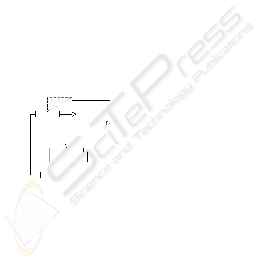
4.2.2 Deployment Diagrams
We use deployment diagrams (figure 2) to map
services with network equipments. A UML node
with a QoS present in its context represents physical
components. A service class represents services. A
realization link associates a
QoS_node with a service.
QoS is specified in
QoS_node and service context.
S e
r
v
ice
Qo S
_
e l e m e n t
Q o S
_
n o de
n o d e
c o n t e x t
l o g i c a l f u n c t i o n n a l i t y
1
r e a l i z a t i o n
1 . . *
F r o m U M L m e t a model
F rom Q o S m o d e l
P h
y
s i c a l
_
c o mponent
r epre s e n t s
Figure 2: Deployment Diagrams Extension.
4.2.3 Objects Diagrams
Objects diagrams represent a class diagram instance.
QoS components become QoS component instances.
The same procedure is applied for the APs. From a
QoS point of view, no change in UML is done. The
dynamic property is reported in QSL. As a result,
static QoS elements cannot be revaluated in UML
dynamic diagrams.
4.2.4 State/Transition Diagrams
We use State/transition diagrams to model the
system behavior. Changing states in the diagram
represents system behavior. QoS components
relationships (service calls, physical link
connections…) change the system state.
Relationships are represented by actions in the
diagram. These actions link two system states. From
a QoS point of view, each state has its own QoS
specification in its context.
4.3 Mapping of UML Concepts to QoS
Specification
QoS component definition is insufficient to solve
QoS integration issue. We define a functional
framework to formalize QoS components
interactions. This framework deals with concepts of
inheritance, composition and association.
4.3.1 Inheritance
A QoS component may use inheritance to specialize
or generalize an existing QoS component. In our
approach, inheritance of QoS components must
ensure functional inheritance and QoS inheritance.
Valued QoS elements are inherited too but cannot be
revalued.
4.3.2 Composition
QoS component composition is the basic abstraction
means in our approach. However, a basic
composition may cause QoS inconsistency. If
several routers compose a network, the issue to deal
with is how to compose router QoS aspects to yield
network QoS aspects. QoS aspect aggregation
cannot represent QoS component composition. Two
points are to be observed:
1. QoS aspects to compose do not have a
common characteristic. In this case, every
component adds its own quality. This
composition can be viewed as a QoS aspect
union.
2. QoS aspects have one or more common
characteristics. In this case, the common QoS
aspects are combined. Rules of combination
are driven by QSL.
4.3.3 Association
We use QoS component association to model
component collaboration and therefore end-to-end
QoS. It is mapped to QoS combination.
COMPONENT BASED METHODOLOGY FOR QOS-AWARE NETWORK DESIGN
193
5 QOS-AWARE NETWORK
DESIGN METHODOLOGY
Reducing network-modeling complexity needs
separating network representation from component
development. In this sense, our network design
methodology (§5.1-5.2) focuses only on network
design and not on component development.
Although our network design methodology does
not take into account QoS components modeling, we
propose a dedicated methodology to design such
components (§5.3).
5.1 Package Organization
When dealing with large networks, the number of
elements to take into account in design process can
be very important. Reducing horizontal complexity
is not sufficient. To achieve this issue, we break this
complexity into vertical views.
Vertical complexity is interested in component
abstraction issues, e.g. in system representation by
different hierarchical levels of granularity. Each
level focuses on network and QoS particular aspects
only in this level. As a result, only the elements
related to this level are represented. We define four
granularity levels:
User level. This level captures components as
seen by a user of the communicating
environment (networks, users…);
Inter Domain level. This level refines the
previous level. It focuses on autonomous
systems collaborations;
Intra Domain level. This level reflects the
network organization from a network provider
point of view. Services deployed and
equipments such as routers may appear at this
level;
Equipment level. This is the lowest level of our
architecture. It represents the services and
architectures deployed in the Intra Domain
level components;
Each level is considered as a package containing
its QoS components. Packages are linked by
realization links. As a result, collaboration of QoS
components from Equipment package allows
realization of QoS components from Intra Domain
level.
5.2 Network Representation
Methodology
Our network development methodology focuses on
representation of the collaboration of the network
elements at a granularity level chosen by the
designer. The network representation fulfils a
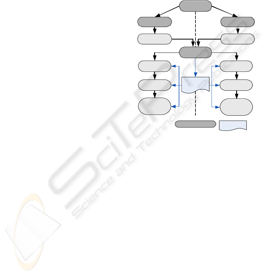
development cycle illustrated in figure 3. This cycle
separates service and architecture views of the
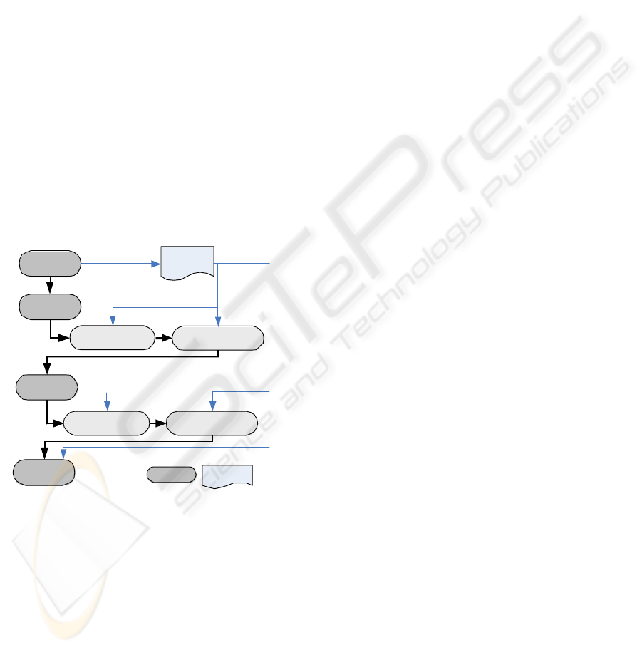
network. Each branch of the cycle follows five steps:
Component Identification, QoS definition, QoS
contract negotiation, Structural modeling, Dynamic
aspects modeling.
Service A r c h i t e c t u r e
separ a t i o n
QoS
Mo d e l
QoS
Defi n i t i o n
Services
design
Step
Dynamic
aspects
modeling
St
r
uctu
r
al
Modeling
Legend
:
D o c u m e nt
Network
D e s i g n
Component
Identification
QoS
contracts
negotiation
A r c h i t e cture
d
e s i gn
D y n a mic
a
s p e cts
m
o d e l i ng
S t
r
u c t u
r
al
M
o d e l i ng
C o m p onent
I
d e n t i f i cation
Q o S
c o n tracts
n
e g o t i a tion
Figure 3: Network Design Cycle.
5.2.1 Component Identification
This step consists in capturing the QoS components
and their QoS relevant to the abstraction level under
consideration. In this step, we use UML Use case
diagrams as defined in section 4.2.1.
5.2.2 QoS Definition
QoS definition step focuses on QoS definition. This
ensures that QoS definitions will be coherent
between the modeling of service and architecture
considerations. This step is realized using a UML
class diagram obtained from QSL definition layer.
5.2.3 QoS Contract Negotiation
This step concerns QoS contract negotiation
between QoS components identified in the first step.
In this sub-step, negotiation styles define how to
compose QoS constraints of the QoS components
modeled in identification step. QoS contract
negotiation step refines Use case diagram produced
in identification step. QoS negotiation terms are
ICSOFT 2007 - International Conference on Software and Data Technologies
194

specified by QSL QoS constraints that are
represented in Use Case context.
5.2.4 Structure Modeling
Structure modeling intends to model static elements
of the network. It consists in three sub-steps:
1. QoS model update. Structure modeling may
involve changes in QoS model. To keep QoS
consistency, these changes are to be reported
in the model produced in QoS definition step.
2. Structure modeling. This sub-step focuses on
static representation of the network. We use a
class diagram composed by QoS components.
This step is derived from use case diagram
produced in the previous steps. QoS actors are
refined in QoS components (service or
physical component) and their AP must be
represented.
3. QoS contract representation. Once QoS
components are modeled, the QoS must be
integrated in the class diagram. Only static
QoS elements are to be instantiated from QSL
definitions. Section 5.2.5 deals with Dynamic
QoS elements specification. Negotiated QoS
contracts specified in QoS Use case element in
the first steps are represented in the context of
AP association between QoS components.
5.2.5 Dynamic Aspects Modeling
The dynamic aspects modeling focuses on QoS
changes representation and error/particular cases
modeling. Three sub-steps are to be considered:
1. Instantaneous state modeling. This sub-step
represents the network at a particular instant
of its lifetime. For this task, we use object
diagrams as presented in section 4.2.3. QoS
components of structure modeling step are
instantiated into QoS component instances.
Static QoS elements are derived from class
diagram without any change. However,
dynamic QoS elements are to be valued.
2. Behavior modeling. This sub-step expresses
the chronology of QoS components
relationships. As the previous sub-step gives
us the different states of the network, we need
linking together these states. For this purpose,
we use state/transitions diagrams as presented
in §4.2.4.
3. Error case modeling. This sub-step requires
examining two cases. If the error case is
unrecoverable, we need a single object
diagram (as §4.2.3.) to model the error state of
the network. If such a situation occurs
validation of system must fail. If the error case
is recoverable, the network can return to a
stable state provided some mechanisms are
activated. We need two diagrams to model
such cases: an object diagram modeling the
error case as if the situation was
unrecoverable, a state/transition diagram
modeling all actions in order to recover from
this error state. As in the two previous sub-
steps, a transition path must start from error
state to a stable state previously modeled.
5.3 QoS Component Development
Methodology
This section provides a design methodology for QoS
Components. When modeling a component, two
cases occur depending on if the component is
managed or not. If the component is managed we
have information about its internal functioning. If
the component is not managed, we do not know how
this component works, we have only non-functional
information. For example, in case of modeling
collaboration between several network domains, we
can model internal components of our domain to
determine its QoS but we do not know internal
components of the other domains. We only have
information from the administrators of these
domains. As a result, we propose a development
cycle adapted for each case.
5.3.1 Managed QoS Components
Developing managed QoS components relies on the
modeling of its internal components collaboration.
We consider that the component to model is seen at
a high-level. Thus, by reducing its vertical
complexity, we determine its QoS. We developed
“3D V” cycle. This cycle is a modified version of
the well-known V cycle. It comprises three V cycles
for each consideration: QoS, functional aspects and
architectural aspects. QoS V cycle is mandatory
adding to one (or two) of the other V cycles
(functional or architecture). Their presence depends
on the elements that are considered in the design.
For example, particular design may ignore
architectural or functional parts.
Each V cycle comprises four levels
corresponding to the vertical complexity concerns:
User, Inter Domain, Intra Domain, and Equipment.
The exploration of 3D V cycle is done as a
conventional V cycle. The entry in the cycle depends
on the level considered to develop the component.
The level of concern for a router is Intra Domain.
COMPONENT BASED METHODOLOGY FOR QOS-AWARE NETWORK DESIGN
195
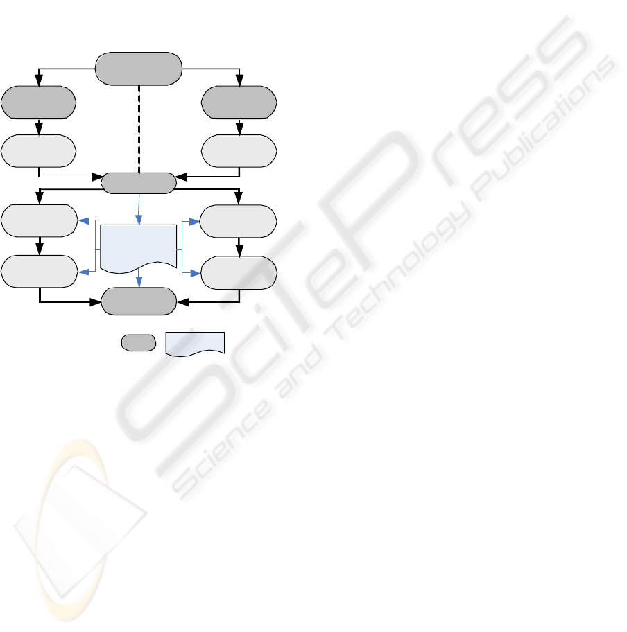
The left branch is the first to be examined. It
consists in modeling all the sub components of the
QoS component considered. The right branch
focuses on the determination of the QoS of the
component.
To develop a QoS component, we explore
simultaneously the three V cycles of the 3D V cycle.
The four development levels obey the same
development cycle in five sub-steps (figure 4): Sub-
component Identification, Static relationships
modeling, QoS definition, Dynamic relationships
modeling and QoS determination.
QoS
Mode l
Q o S
Defi n i t i o n
S u b - s e r v i c e s
D e s i g n
step
D
y
n a m i c
r e l a t i o n s h i p s
m o d e l i n g
S t a t i c
r
e l a t i o n s h i p s
m o d e l i n g
QoS
D e t e
r
min a t i o n
L e g e n d :
D o c u m e n t
A d m i n i ster e d
Q o S
c o m p o nen t
D e s i g n
T
h e
Q o S
C o m p o n e n t
i s
a
S e
r
v
i c e
T
h e
Q o S
C omponent
i
s
p h
y
s i c a l
I f
a l l
s u b - c o m p o n e n t s
a r e
d e s i g n e d
I f
a l l
s u b - c omponents
a
r e
d e s i g ned
S u b - s e r v i c e s
i d e n t i f i c a t i o n
D
y
namic
r
e l a tionships
m
odeling
Static
r
e l a tionships
m
odeling
I nner
c
o mponents
i
d e ntification
I nner
C
o mponents
Design
Sub-component de sign
Figure 4: Managed QoS Components Modeling.
Sub Component Modeling
This step focuses on services or architectural
components. No architectural aspects are considered
here. This step is organized in three sub-steps:
1. Sub-services Identification. This step aims to
capture services which collaborations realize
the component service to model, and link two
abstraction levels (relationships between a
service and its inner components). We use a
class diagram. The service to develop is
captured as a single class composed by its
sub-services. If the service belongs to
abstraction level n, sub-services belong to
abstraction level n-1.
2. Static relationships modeling. In this sub-step,
relationships between sub-services are
modeled. For this purpose, we use a class
diagram built as in section 5.2.4.
3. Dynamic relationships modeling. This sub-
step captures the QoS relative to the dynamic
aspects of the sub-services collaboration.
These dynamic aspects model the behavior of
the service. It is captured with a
state/transition diagram representing the
different states of the service. Each state is
captured with an object diagram as in the
section 5.2.5. As a service may have several
functionalities, several state/transitions
diagrams may be built. These diagrams are
organized with a UML activity diagram. No
QoS can be captured at this step.
Service Deployment
The separation of functional/architectural
considerations implies to check if the QoS of the
modeled services is consistent with the QoS of the
architecture. To ensure this consistency, we need a
representation of service deployment on the
component architecture. A deployment diagram (as
seen in section 4.2.2.) represents this fact. QoS
offered by the architecture must be greater than QoS
offered by the services. QSL allows such
comparisons. In case of QoS inconsistency,
development process must reconsider:
The service-modeling step if the QoS offered
by the services is excessive. Designer must
change QoS offered or change one or more
service components;
The architecture modeling step if the
architecture is not sufficient.
QoS Determination
At this step, we must determine the components
QoS. We use the rules defined in section 4.3.2 to
compose QoS components each other. QoS
constraint derivation from one component to another
is done according to the associations of the
components (type and cardinality), the access point
type and the constraint type (offered, required and
admitted).
5.3.2 Unmanaged QoS Components
In this case, it is assumed that the designer cannot
manage the component. As a result, he/she only has
little information about it. This step provides means
to capture this component for it to be integrated in
the network design process. We separate QoS,
functional and architectural considerations. Six steps
(figure 5) compose the component design cycle:
1. QoS definition (described in section 5.2.2.).
2. Static service modeling. This step focuses on
modeling the services offered by the
ICSOFT 2007 - International Conference on Software and Data Technologies
196
component. We use a class diagram that
contains at least a Service component, its
access points and QoS elements specified in
QSL as presented in section 4.1.
3. Dynamic service modeling. Dynamic service
modeling uses state/transition diagrams as in
section 5.2.5.
4. Static architecture modeling. This step uses a
class diagram as in static service modeling
step.
5. Dynamic architecture modeling. This step
represents the component architecture and its
changes. The modeling of architecture stable
states drives architecture modeling. Modeling
of such states is realized with object diagrams
instantiated from the class diagram of the
static architecture-modeling step. Activity
diagrams capture architecture changes. Each
activity represents a stable state of the
component architecture, e.g. an object
diagram. Changes are represented by
transitions between these activities.
6. Service deployment. This step is presented in
section 5.3.1.3.
Q o S
M o d e l
S t a t i c
A
r
c h i t e c t u
r
e
M
o d e l i n g
A
r
c h i t e c t u
r
e
D e s i g n
Q o S
D e f i n i t i o n
S e
r
v i c e
D e s i g n
S t e p
D
y
n a m i c
S e
r
vices
M
o d e l i n g
S t a t i c
S e
r
v i ce
M
o d e l i n g
D
y
n a m i c
A
r
c h i t ectu
r
e
M
o d e l i n g
S e
r
v i c e
D e p l o
y
m e n t
L e g e n d :
D o c u ment
Figure 5: Unmanaged QoS Components Modeling.
6 CONCLUSIONS
In this paper, we present a complete QoS-aware
methodology to design networks. This methodology
relies on a QoS specification language QSL, UML
extensions and a design cycle. Design cycles intend
to reduce network complexity by focusing network
representation on QoS components collaborations.
Services, equipments and their QoS (properties and
constraints) are captured and means are provided for
combining these elements. We expose two design
cycles to model QoS components, depending on
whether these components are administered or not.
Unmanaged components are represented with
fragment information, provided QoS is known.
Managed components are modeled by the
combination of their sub-components. We presented
ways to determine the resulting QoS from this
combination.
This work is being integrated in a wider
framework for QoS specification and verification of
networks and users requirements. The way to
continue this work is developing a validation
framework for the produced models.
REFERENCES
Aagendal, J.O., 2001. PhD Thesis. Quality of Service
Support in Development of Distributed Systems,
Department of Informatics, University of Oslo.
Frølund, S., Koistinen, J., 1998, QML: A Language for
Quality of Service Specification, Hewlett-Packard
Labs Technical Report.
Gu, X., Wichadakul, D., Narhstedt, K., 2001. Visual QoS
Programming Environment for Ubiquitous Multimedia
Services. In ICME2001.
ISO/ITU, 1997. Information technology -- Quality of
service: Framework, ISO/CEI 13236 norm / ITU-T
X.641 Recommendation.
Mammeri, Z., 2004. Towards a formal model for QoS
specification and handling in Networks. In IWQoS
2004 proceedings.
Object Management Group, 2003. Unified Modeling
Language v1.5, formal/03-03-01.
Object Management Group, 2003. Schedulability,
Performance and Time Profile, formal/03 09 01.
Object Management Group, 2004. UML Profile for
Modeling Quality of Service and Fault Tolerance
Characteristics and Mechanisms.
Object Management Group, 2004. Common Object
Request Broker Architecture (CORBA) revision 3.0.3.
Teyssié, C., 2005. UML-based Approach for Network
QoS Specification”. In ICN’05 proceedings.
Wang, Z., Crowcroft, J., 1996. Quality of Service Routing
for Supporting Multimedia Applications. In IEEE
JSAC 14(7).
Zinky, J.A., Baken, D.E., Schantz, R.E, 1997.
“Architectural Support for Quality of Service for
CORBA Objects”, in Theory and Practice of Objects
Systems, 1997.
COMPONENT BASED METHODOLOGY FOR QOS-AWARE NETWORK DESIGN
197
