
A FORMAL APPROACH TO DEPLOY HETEROGENEOUS
SOFTWARE COMPONENTS IN A PLC
Mohamed Khalgui and Emanuele Carpanzano
ITIA - Institute of Industrial Technologies and Automation CNR 20131 Milan, Italy
Keywords:
Component Based Technologies, Industrial Control Systems, Multi-tasking PLCs, Deployment, Real-Time
Scheduling.
Abstract:
This paper deals with an industrial control application following different component-based technologies.
This application, considered as a network of heterogeneous components, has to be deployed in a multi-tasking
PLC. It has classically to respect temporal constraints according to specifications. To deploy the components in
feasible OS tasks of the controller, we propose to fix a formal component model allowing their homogeneous
design. We enrich, in particular, this model to unify well known technologies. The application is considered
then as a network of homogeneous components. We propose to transform this network into a real-time tasks
system with precedence constraints to exploit previous results on real-time deployment.
1 INTRODUCTION
The development of critical industrial control appli-
cations is nowadays a very complicated activity basi-
cally due to the always increasing set of functional
and non-functional requirements. Control applica-
tions have to satisfy stringent real-time constraints
that are difficult to be addressed following the tradi-
tional development approaches. This problem is more
complicated by the continuously increasing demand
for shorter development time. This also imposes the
demand for shorter verification phase. The compo-
nent based development is widely accepted by indus-
try as a successful paradigm to address these require-
ments (Crnkovic and Larsson, 2002).
Nowadays, several component based technologies
have been proposed to develop control applications
(Crnkovic and Larsson, 2002). These technologies
allow to reuse already developed components avail-
able in rich libraries. In addition, they support the
modularity reducing the design complexity. Never-
theless, the majority of these technologies depend on
particular companies or projects (Crnkovic and Lars-
son, 2002). Therefore, the use of the corresponding
libraires is limited.
In this paper, we propose to reduce the realiza-
tion time of applications by exploiting the advan-
tage and also the component library of each one of
the known component-based technologies. Therefore,
a control application is a network of heterogeneous
components following different technologies. These
components have classically to respect functional and
temporal constraints described in specifications. To
our knowledge, there is no approach considering such
functional architecture of component-based applica-
tions. The problem that we tackle in this paper is how
can we validate the application components whereas
they are developed using different technologies (fig-
ure 1)? Moreover, how can we deploy these compo-
nents in feasible OS tasks of a PLC ?
To resolve this problem, we propose to fix a for-
mal component model (Sifakis, 2005) to unify all the
known component-based technologies. In addition,
we enrich this model to take into account character-
istics of these technologies. Thanks to this model,
the application is transformed then into a network of
homogeneous components having the same charac-
teristics. To correctly deploy these components, we
propose to transform them into a real-time tasks sys-
tem with precedence constraints. The purpose is to
exploit previous results on deployment and schedul-
ing of component-based applications (Khalgui et al.,
207
Khalgui M. and Carpanzano E. (2007).
A FORMAL APPROACH TO DEPLOY HETEROGENEOUS SOFTWARE COMPONENTS IN A PLC.
In Proceedings of the Second Inter national Conference on Software and Data Technologies - SE, pages 207-212
DOI: 10.5220/0001340502070212
Copyright
c
SciTePress
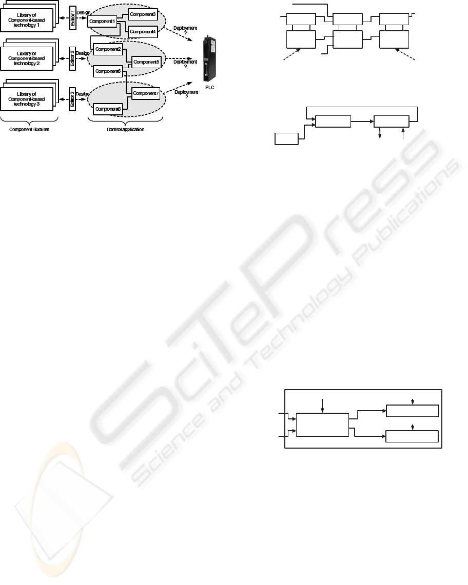
Figure 1: Deployment of a control application based on het-
erogeneous components.
2006).
In the section 2, we briefly present the well known
industrial component-based technologies. Then, we
detail a particular approach that we exploit in all the
continuation as a unifying component model. In the
section 4, we propose to enrich this formal approach
to be compliant with the known industrial technolo-
gies. To deploy a control application, we propose in
the section 5 to transform the corresponding homoge-
neous components into a subtasks system with prece-
dence constraints.
2 COMPONENT-BASED
TECHNOLOGIES
Nowadays, several component-based technologies
have been proposed to develop industrial control ap-
plications (Crnkovic and Larsson, 2002). These tech-
nologies depend often on particular industrial compa-
nies or projects. Each one proposes a particular char-
acterization of the component concept. In this section,
we briefly present the most known technologies in in-
dustry.
The IEC 61499 standard (Crnkovic and Larsson,
2002) is a component-based standard allowing the de-
velopment of distributed control applications. Ac-
cording to this standard, a function block is a an event
triggered component owning data and an application
is a network of blocks. In the figure 2, we present
a simple example of a Temperature Regulator pro-
posed in (Lewis, 2002). This regulator is composed
of two interfaces blocks (Input1 and Output1) and a
regulation block PID1. A detailed description of this
example is available in (Lewis, 2002).
The Carnegie Mellon university proposes also its
owner component concept named Port Based Object
(Crnkovic and Larsson, 2002). This technology is of-
ten used to develop industrial control applications in
E_RunE_Exo E_Init
E_Run
E_Exo
E_Exo
E_ExoE_Run
Out
PV
SP
Out
Out
E_Init
Setpoint
Input1 Output1PID1
Temperature sensor Heater actuator
Figure 2: A FB Component : TemperatureRegulator.
Regulate Interface
Cyclic
Actuator Actuator
V
mesured
V
desired
V
regulated
V
mesured
Figure 3: A PBO Component : Speed Regulator.
robotics. A PBO component is a particular case of
a Function Block. The figure 3 presents the Speed
Regulator as a simple example of PBO components
regulating the vehicle speed. The component Cyclic
sends periodically the desired values to Regulate
which regulates the values measured from the com-
ponent Inter face (Crnkovic and Larsson, 2002).
The Arcticus Systems propose also another com-
ponent model called ”Rubus” (Crnkovic and Larsson,
2002). This technology allows to consider functional
and temporal constraints on application components.
In the figure 4, we present BrakeSystem as a simple
example of Rubus components to use in a vehicle.
The component BrakeLe ftRight allows to brake left
or right by considering the pressure and also the speed
of the vehicle.
Task :
BrakeLeftRight
Task :
OutputBrakeleft
Pressure
Speed
Task state information Task state information
brake left
brake right
Task :
OutputBrakeright
Task state information
Figure 4: A Rubus Component : BrakeSystem.
By studying these component-based technologies,
the component concept is quietly the same from a
technology to another. In addition, these technolo-
gies provide rich libraries. Therefore, it is interesting
to exploit them in the order to reduce the realization
time of an industrial control application. In all the
continuation, we consider a control application as a
network of heterogeneous components following dif-
ferent technologies.
ICSOFT 2007 - International Conference on Software and Data Technologies
208
3 FORMALIZATION
To cover all the component-based technologies, we
propose to fix a formal approach unifying the compo-
nent concept. Nowadays, several formal approaches
have been proposed. In this paper, we select the best
one that supports a detail specification of interactions
between components (Sifakis, 2005). This approach
defines classically a component as interfaces and an
implementation. Let us consider an application con-
taining K components. According to (Sifakis, 2005),
the application is characterized by a set of actions A
supporting its different functionalities. An application
component comp
i
i ∈ [1,K] is a subset of actions A
i
(A
i
⊂ A). An action is implemented by an algorithms
sequence in the component. We note, in addition, that
the application components are with disjoined subsets
of actions (A
i
∩ A
j
=
/
0). To specify an application,
(Sifakis, 2005) proposes the following models :
• Interaction model : defines the interactions be-
tween the application components.
• Behavior model : defines the behavior of each
application component.
• Execution model : defines a fixed priority policy
allowing the execution of the application compo-
nents.
In this paper, we just describe the two first models.
3.0.1 Interaction Model
To specify interactions between components, (Sifakis,
2005) defines the connector concept. A connector c
defines a maximally compatible set of interacting ac-
tions between components. It is a non empty subset
of A such as
∀i ∈ K,
|
A
i
∩ c
|
≤ 1
Given a connector c, an interaction α of c is de-
fined in (Sifakis, 2005) as any term of the form
α = a
1
|a
2
....|a
n
,{a
1
,...., a
n
} ⊆ c
The operator ”|” is a binary associative and com-
mutative operator. It is used to denote a composition
of actions. The interaction a
1
|a
2
....|a
n
is the result
of simultaneous occurrences (or execution) of the ac-
tions a
1
,....., a
n
. Note that if α = a
1
|a
2
....|a
n
is an
interaction of a connector, then any term correspond-
ing to a subset of {a
1
,a
2
....,a
n
} is also an interaction.
Finally, one denotes by I(c) (resp, I(C)) the set of in-
teractions corresponding to a connector c (a set C of
connectors).
Producer Consumer
put get
Figure 5: Producer / Consumer composition.
putprod consget
Producer
Consumer
Figure 6: The behavioral model.
3.0.2 Behavioral Model
According to (Sifakis, 2005), the behavior of an ap-
plication component is defined as a transitions sys-
tem. This system is classically characterized by a
triple (Q,I(A),→) where,
• Q is a set of states,
• I(A) is a set of interactions between actions of A,
• →⊆ QXI(A)XQ is a transition relation. As usual,
one writes q
1
α
→
q
2
to denote a transition be-
tween q
1
and q
2
.
3.1 Example
To illustrate these two models, we present in the figure
5 the classic example of Producer/Consumer. These
two components interact together through the put|get
of the connector {put, get}. We present in the fig-
ure 6 the behavioral models of the two components.
We note that prod and cons are internal actions of the
components Producer and Consumer.
4 EXTENSIONS AND
ASSUMPTIONS
Although this formal approach is expressive to model
component based applications, it is not compli-
ant with the known component-based technologies.
Therefore, we propose to enrich this approach by sev-
eral concepts. We propose to classify first of all the
component actions in input, internal and output ac-
tions. In addition, we propose a functional and tem-
poral characterization of a control application.
4.1 Component Actions
Let c be a component of a control application. We
propose the following sets to characterize the corre-
A FORMAL APPROACH TO DEPLOY HETEROGENEOUS SOFTWARE COMPONENTS IN A PLC
209

sponding actions :
• external(c) : the set of input/output actions (in c)
interacting with outside.
• internal(c) : the set of internal actions (in c). An
internal action can be activated by more than one
input action.
We define for each internal action act of a compo-
nent c (act ∈ internal(c)) the following external ac-
tions :
• input(act) : a set of input actions activating act
(input(act) ⊆ external(c)).
• output(act) : a set of output actions to activate
once the execution of act finishes (output(act) ⊆
external(c)).
Finally, we denote by In
Act (resp, Out Act) the
set of input (resp, output) actions in the application (∀
act ∈ internal(c), input(act) ⊂ In Act, output(act)
⊂ Out
Act).
4.2 Composition of Components
To be compliant with several industrial component-
based technologies, we enrich the functional architec-
ture of a control application.
4.2.1 Container Concept
In several component-based technologies (Crnkovic
and Larsson, 2002), the container concept is proposed
to gather application components controlling physical
processes. A container is a logical execution unit cor-
responding to time slots of the processing unit. In this
paper, we propose the following definition of a con-
tainer.
Definition. a container is a set of application
components sharing the control of physical processes.
It is characterized by a sequencing function defining
the static scheduling of the internal components. We
apply a non-preemptive policy to process this func-
tion.
In the operational architecture, we propose to con-
sider a container as an OS task. This task imple-
ments all the possible execution scenarios of the in-
ternal components. The sequencing function of the
container is the ”main()” function of this task.
4.2.2 Temporal Constraints
We propose the function cause specifying causalities
between output actions of application components
and input actions of another ones. Two actions are
under a causality constraint if they belong to a same
interaction of a connector.
∀ia ∈ In
Act,
cause(ia,c) = {ϕ ∈ Out
Act/∃i ∈ I(C),{ia} ∪ ϕ ∈ i}
In the Producer/Consumer example, we note that
cause(get,consumer) = {put}. According to specifi-
cations, we define End to End Response Time Bounds
between periodic readings from sensors and the acti-
vation of the corresponding actuators. The scheduling
of the application components has to take into account
these bounds.
Finally, by considering this formal approach, each
control application (following different technologies)
becomes a network of homogeneous components dis-
tributed on several containers of a controller. Ac-
cording to specifications, these components have to
respect bounds on their response times.
Running example. In all the continuation, we
consider as an example a control application embed-
ded in a vehicle. This application is composed of the
following sub-applications to distribute on three con-
tainers :
• The temperature regulator developed while fol-
lowing the IEC 61499 technology.
• The speed regulator developed while following the
PBO technology.
• The brake system developed while following the
Rubus technology.
To deploy the application in OS tasks of the exe-
cution support, we have to transform the correspond-
ing heterogeneous components into formal homoge-
neous ones (figure 7). In the container 1 containing
components controlling the break system, we distin-
guish two interactions : act
out le ft | act left and
act
out right | act right. In this container, when the
input actions (act
pres and act speed) of Comp1 are
activated, we have to execute the internal action Act1
deducing the brake to activate. Once the execution
ends, we activate act
out le ft OR act out right de-
pending on the data pressure and speed.
5 SUBTASKS SYSTEM
Once the heterogeneous components of the applica-
tion are unified in a same model, the remaining prob-
lem is to deploy them in feasible OS tasks of the ex-
ecution support. We propose to transform first of all
these components into a subtasks system with prece-
dence constraints. The purpose is to exploit previous
results on the real-time scheduling. We define the fol-
lowing concepts characterizing such system.
ICSOFT 2007 - International Conference on Software and Data Technologies
210
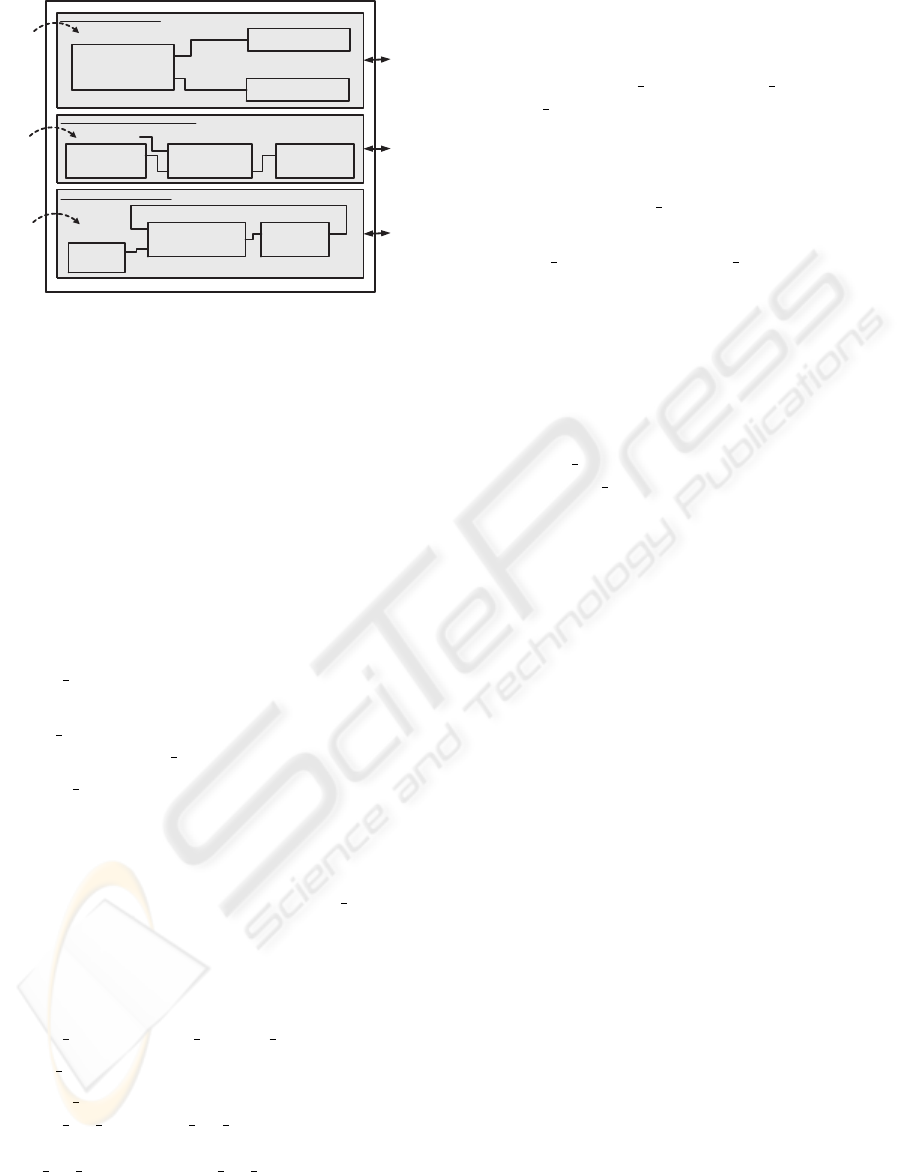
Act1
Act2
brake left
brake right
Act3
act_pres
act_speed
act_out_left
act_out_right
Comp1
Comp2
Comp3
act_left
act_right
container 1 : BrakeSystem
Act4
act4_run act4_exo
Init, Act5
act5_init
act5_run
act5_exo1
act5_exo2
Act6
act6_run act6_exo
container 2 : Temperature regulator
Comp4 Comp5 Comp6
Act8
act_mesured
act_desired
act_reg
Act7
out_cyc
Act9
act_reg act_mes
V
mesured
V
desired
container 3 : Speed regulator
Device
Comp7
Comp8 Comp9
PBO
technology
FBs
technology
Rubus
technology
Brakes
Heater
Regulator
Figure 7: Distribution of the formal components on con-
tainers of the execution support.
5.1 Subtask
An application subtask, denoted by sub, corresponds
to an execution of a component c when corresponding
input actions are activated. In addition to these ac-
tions, the subtask sub implements the corresponding
internal and output actions of the component. To gen-
erate the different subtasks of a component, we have
quite simply to analyze the corresponding behavioral
model. In this paper, we propose the following func-
tions defining a subtask of a component.
• cause
of (sub) : defines the input actions activat-
ing the execution of sub.
• code o f(sub) : defines the internal actions to exe-
cute once the cause
of (sub) actions are activated.
• e f fect
of (sub) : defines supersets of output ac-
tions. These sets are generated while applying an
analysis of the interaction model. Each set repre-
sents a possible execution scenario of the compo-
nent. At run-time, we have to execute only one of
them depending on the execution of code
of (sub)
actions.
Running example. In the example, we define for
the componentComp1 a subtask Sub1. We character-
ize this subtask as follows,
• cause
of (sub) = {act pres,act speed}
• code
of (sub) = {Act1}
• e f fect
of (sub) =
{{act
out le ft},{act out right}}. Once the
execution of Act1 finishes, we have to execute
act out left OR only act out right.
Let Σ be the set of the application subtasks. We
propose to characterize a component subtask sub as
follows,
• WCET(sub) (resp, BCET(sub)) : the Worst
(resp, Best) Case Execution Times of the
algorithms implementing the actions be-
longing to cause
of (sub), code of (sub) and
ef fect
of (sub).
• pred(sub) : a set of sub-tasks to execute in the
application before sub. These subtasks belong to
components that contain the output actions acti-
vating those of cause
of (sub).
pred(sub) = {sub
′
∈ Σ/∃ia ∈
cause
of (sub),∃ψ ∈ ef fect o f(sub
′
),∃oa ∈
ψ,oa ∈ cause(ia)}
• succ(sub) : a set of subtasks sets. Each subtasks
set corresponds to a possible execution scenario
(ie. only one subtasks set between all ones is ex-
ecuted at run-time). The subtasks of a set have to
be executed once the execution of sub is finished.
succ(sub) = {φ ⊂ Σ/∃ψ ∈
ef fect
of (sub),∀oa ∈ ψ, ∃sub
′
∈ φ,∃ia ∈
cause
of (sub
′
),oa ∈ cause(ia)}
Let σ be a subset of Σ. This subset corresponds
to a particular container of the application. We de-
note by first(σ) (resp last(σ)) the set of subtasks with
no predecessors (resp successors) in σ. In this paper,
we propose particularly to characterize each subtask
sub of first(σ) by a release time r(sub) and a period
p(sub).
Running example. In the followed example, the
subtask sub1 is with no predecessors. In addition,
once it is executed, we have to execute the subtasks
sub2 OR sub3 depending on the pressure and the
Speed.
pred(sub1) =
/
0; pred(sub2) = {sub1}
succ(sub1) = {{sub2},{sub3}}
5.2 Subtasks Trace
By considering the precedence constraints between
subtasks, we define a trace tr of σ the following se-
quence,
tr = sub
0
, sub
1
...., sub
n−1
such as,
• ∀sub
i
∈ [1,n− 1],sub
i−1
∈ pred(sub
i
).
• sub
0
∈ first(σ) and sub
n−1
∈ last(σ).
The trace tr implements a possible execution sce-
nario of σ. Such execution has to respect a particular
end to end response time bound (between the activa-
tion of sub
0
and the execution end of sub
n−1
) accord-
ing to specifications.
Running example. In the same followed example,
we distinguish two traces in the first container.
A FORMAL APPROACH TO DEPLOY HETEROGENEOUS SOFTWARE COMPONENTS IN A PLC
211
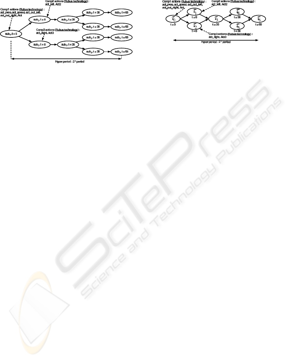
Figure 8: Temporal validation of the container1 containing
Rubus components
trace
1
= sub
1
,sub
2
and trace
2
= sub
1
,sub
3
6 DEPLOYMENT OF
COMPONENTS
Once the application components are correctly trans-
formed into a system of subtasks with precedence
constraints, the problem is to deploy them in feasible
OS tasks of a PLC. We propose to apply the approach
particularly proposed in (Khalgui et al., 2006) for the
deployment of systems of real-time subtasks. Accord-
ing to this approach, we apply a schedulability anal-
ysis on each container to check the internal blocks.
This analysis is based on a generation of an accessi-
bility graph that we propose. Once all the containers
are feasible, we propose to transform them into inde-
pendent OS tasks before checking their on-line pre-
emptive feasibility (Khalgui et al., 2006).
Running example. In the followed example, we
suppose periodic readings of the pressure and the
speed values (the release time r = 5 and the pe-
riod p = 30). Moreover, we suppose that the worst
and best case execution times of each action act
(act ∈ Σ) are bcet(act) = wcet(act) = 1. Therefore,
BCET(sub
1
) = WCET(sub
1
) = 3. In the figure 8,
we present the accessibility graph corresponding to
the container 1. Once the container 1 is temporally
validated, we construct a corresponding OS task that
implements the different execution scenarios of the in-
ternal components (figure 9). The processed sequenc-
ing function is the main() function of this task where
each subtask implements a set of application actions
(Khalgui et al., 2006).
7 CONCLUSION
This paper deals with the deployment of industrial
control applications following different component-
Figure 9: OS task implementing the first container contain-
ing Rubus components.
based technologies. The purpose is to reduce the real-
ization time by exploiting the advantages and the dif-
ferent libraries of these technologies. To deploy the
application on a multi-tasking PLC while satisfying
the specifications constraints, we propose to fix a par-
ticular formal component-based approach in the or-
der to cover all the known technologies. We propose
also to enrich this approach to be compliant with these
technologies. Therefore, the heterogeneous compo-
nents of the application are considered as homoge-
neous formal ones. We propose to transform them
into a subtasks system with precedence constraints to
construct corresponding feasible OS tasks in the PLC.
In the future works, we plan to extend our research
by considering re-configurable applications following
different technologies. We have, first of all, to de-
fine the different reconfiguration scenarios of the het-
erogeneous components of the application. Then we
have to study their deployment for each scenario case.
REFERENCES
Crnkovic, I. and Larsson, M. (2002). Building reliable
component-based software systems. Artech House.
London.
Khalgui, M., Rebeuf, X., and Simonot-Lion, F. (2006).
Component-based deployment of industrial control
systems : an hybrid scheduling approach. In ETFA06,
Czech.
Lewis, R. (2002). Modelling Control Systems using
IEC61499. The institution of Electrical Engineers.
Sifakis, J. (2005). A Framework for Component-based Con-
struction. 3rd IEEE International Conference on Soft-
ware Engineering and Formal Methods (SEFM05).
ICSOFT 2007 - International Conference on Software and Data Technologies
212
