
VEHICULAR ELECTRONIC DEVICES CONNECTED BY
ONBOARD FIELDBUS TECHNOLOGIES
Miguel A. Domínguez, Perfecto Mariño, Francisco Poza and Santiago Otero
Electronic Technology Department
University of Vigo
E.T.S.I. Industriales, Campus Lagoas-Marcosende, 36280, Spain
Keywords: Vehicular Control, Fieldbuses, CAN, City Public Transport Buses, Multiplexed Solutions.
Abstract: The electrical circuits and their Electronic Control Units (ECUs) in buses and coaches are essential for their
good working. Drive, braking, suspension, opening door, security and communication devices must be
integrated in a reliable and real time information system. The industrial communication networks or
fieldbuses are a good solution to implement networked control systems for the onboard electronics in the
public transport buses and coaches. The authors are working in the design of multiplexed solutions based on
fieldbuses to integrate the body and chassis functions of city public transport buses. An example for the
EURO5 model of the Scania manufacturer is reported in this paper. The authors are also working in the
implementation of new modules based on FPGAs (Field Programmable Gate Arrays) that can be used in
these networked control systems.
1 INTRODUCTION
Nowadays, the commercial buses and coaches are
more and more equipped with electronic devices that
make it easier to drive the vehicle and improve their
security and comfort. These electronic devices are
applied to functions such as Electronic Stability
Program (ESP), braking help system (ABS), gear
control, light control, climate control, opening door
control, navigation and guide (based on GPS: Global
Positioning System and GIS: Geographic
Information System), etc. These functions require
the use of reliable and real time exchange of
information between the different control systems
and the sensors and actuators. Thus, it becomes
necessary the use of an industrial communication
network or fieldbus (Marsh, 1999).
At the beginnings of 1980s the engineers of the
automobile manufacturers assessed the existing
fieldbuses for their using in vehicles. They came to
the conclusion that any of these protocols fulfilled
their requirements. It supposes the development of
new fieldbus protocols (Mariño, 2003).
Each manufacturer has bet for a particular
solution. For example, Bosch developed the CAN
protocol, Volkswagen implemented the A-BUS,
Renault and the PSA Consortium used the VAN
protocol, BMW tried it with the M-BUS and Honda
with the DLCS. The majority of these manufacturers
evolved and adopted for the general purpose
communication the CAN standard (Bosch, 1991)
(ISO 11898, 1992) (ISO 11519-2, 1995).
For other functionalities, such as low speed smart
sensors, multimedia, high speed and safety
applications, the manufacturers are adopting other
protocols in the last years. For example, the Firewire
(IEEE 1394), MOST (Estevez, 2004), D2B optical
and D2B Smartwirex are used for high speed
multimedia applications; TTP, Byteflight and
FlexRay for high speed and safety applications; and
LIN for low speed smart sensor communication
(Marsh, 2005) (Bender, 2004).
2 MULTIPLEXED SOLUTIONS
The buses and coaches used in the city public
transport have a lot of onboard electronic systems,
which must be integrated in an efficient way. These
systems must be connected to a single industrial
communication network with a Central Electronic
Control (CEC) node that manages, in real time, all
the information transmitted from the control
modules installed in the vehicle.
5
A. Domínguez M., Mariño P., Poza F. and Otero S. (2007).
VEHICULAR ELECTRONIC DEVICES CONNECTED BY ONBOARD FIELDBUS TECHNOLOGIES.
In Proceedings of the Fourth International Conference on Informatics in Control, Automation and Robotics, pages 5-10
DOI: 10.5220/0001616200050010
Copyright
c
SciTePress
There are several chassis manufacturers (Man,
Volvo, Scania, Iveco, Renault, Mercedes, etc.) and
every one proposed a different multiplexed solution.
But the use of the CAN protocol and other fieldbus
protocols based on CAN (for example SAE J1939)
(SAE, 2005) is a common point in these solutions.
The multiplexed networks installed in the city-
buses and coaches get an important reduction of the
wiring that involves a reduction in costs, less
breakdown risks and a simple scalability. The
maintenance is easier and the global management of
the technological systems is improved. The
transmission of the information is integrated with a
very low error rate. The control of the systems is in
real time supporting very high elemental information
traffic with command messages for actuators, data
from sensors and alarm events.
2.1 Structure of the Network
A generic structure of communication used in the
multiplexed solutions implemented currently in city
public transport buses is presented in this section.
The main problem in the public transport buses is
the increase of the requirements imposed to the
electronic and electrical systems. It is getting more
and more difficult to find adequate places for
plugging the components with the corresponding
wiring. The installation of circuits based on relays,
diodes and resistors is very complicate.
Other topic to take into account is the satisfaction
of the customer needs in a flexible and fast way. It is
difficult and expensive. A manual process according
to the documentation must implement the relay
switching. The electromechanical circuits have a
limited lifetime. The use of electronic switches in
power circuits is a good solution because achieve the
life time of the vehicle, increasing their reliability
and reducing the time out of service.
Due to the problems related before, the CAN
data bus has become into the automobile technology.
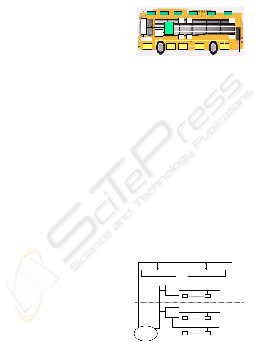
Thus, an example of a multiplexed solution based on
the CAN protocol for data communication in a city
public transport bus is shown in figure 1.
Independent data fieldbuses are used for the
different areas in the system.
The bus manufacturers have trend towards the
use of the VDV (Verband Deutscher
Verkehrsunternehmen) recommendation 234 (VDV,
1996) for the onboard information system integrated
in the dashboard. Therefore, the central unit must be
equipped with a VDV interface module.
CENTRAL
UNI T
DASHBOARD
Tachometer
Ge ar b ox EBS EDC
ECAS
EFR
RAS- EC
VDV
Interface
BM1 BM2 BMx
BM1 BM2 BMx
Door Plat form DoorCl i ma t e Cl i ma t e Cl i mat e
125 Kbps I-CAN
250 Kbps M-CAN
125 Kbps
B- CAN 1 and 2
125 Kbps B-CAN 3
Figure 1: An example of multiplexed solution.
The central unit must execute the classic
functions for the vehicle control and manage the
data traffic from the different CAN fieldbuses. Thus,
the central unit can report a full onboard diagnosis.
A typical multiplexed solution must consider the
integration of a video surveillance system and the
information for the passengers. This integration can
be implemented using a CAN network or other
fieldbuses more adequate for multimedia
information (J1708, WorldFIP, IEEE 1394/Firewire,
etc.). An example of the levels in a complete
communication system is shown in figure 2.
2.2 Reliability
The chassis and body electronic reliability is very
important in the public transport buses and coaches.
The central unit should not connect and disconnect
any power circuit. Based on city-bus manufacturers
knowledge, under this rule, the central unit will only
be implicated in one of each one thousand failures.
Three body CAN buses are contemplated to
communicate several body modules with the aim to
reduce the consequences of a breakdown. These
body modules should be protected against a global
overload with two security devices. Therefore, the
effects in case of failures are minimized.
PUBLIC TRANSPORT SYSTEM VIDEO SURVEILLANCE SYSTEM
PASSENGERS
ISO 11898 CAN network, J1708, WorldFIP, Firewire, ...
BODY
MODULE
BODY
CHASSIS
MODULE
CHASSIS
DASHBOARD
ISO 11898 CAN network
ISO 11898 CAN network
ISO 11898 CAN network
(SAE J1939)
ISO 11898 CAN network
(SAE J1939)
Figure 2: Levels in a typical city public transport bus.
ICINCO 2007 - International Conference on Informatics in Control, Automation and Robotics
6
The modules control their outputs according to
the programmed emergency function when failures
are detected in the data fieldbus. In this way, the
outputs can be permanent connected, permanent
disconnected, intermittent connected or maintaining
the last state.
Other important application to get a good
reliability is that the body and chassis electronic
system supports a wide diagnostic. The central unit
should manage all the CAN networks and implement
their own diagnostic of the body and chassis
electronic system. Every output of the body modules
should be revised periodically to check that there are
not short circuits, overloads and interruptions. The
inputs should be controlled according to the
technical possibilities of the connected sensors.
2.3 Challenges
Every chassis manufacturer has developed its own
multiplexed solution based on CAN. The great
inversions made from manufacturers imply that
every one wants to impose its solution. The
integration problem is for the coachbuilder that
works with chassis from different manufacturers (ten
or more chassis). Each chassis has a different
multiplexed solution and only the modules chosen
by the manufacturer can be used. It involves that the
coachbuilder cannot have their own CAN system (an
unified management for the electrical part of the
body and chassis) and must use the modules chosen
by the manufacturer with a non-competitive price.
The SAE Truck and Bus Control and
Communications Sub-committee has developed the
J1939 standard. The J1939 standard is necessary to
sort the codifications that each manufacturer has
used to specify the same peripheral unit (device,
sensor) or the set of the units connected to the CAN
network in the city-buses and coaches. Besides of
the codification of the terminals, the standard
defines several common parameters and data rates.
Thus, the J1939 standard enables to the coachbuilder
connecting different modules to the CAN system
independently of the manufacturer.
3 DESIGN OF A NETWORKED
CONTROL SYSTEM
The authors are working in the design of a
networked control system that is a multiplexed
solution to integrate the onboard electronic devices
present in a typical city public transport bus. This
system should integrate all the sensors and actuators
present in the vehicle in an optimum way. Besides, it
must resolve those particular functions that actually
are not integrated in the multiplexed solutions of the
chassis manufacturers (Domínguez, 2006).
The paper will describe an example of design for
a vehicle of the Sweden chassis manufacturer
Scania. The features of the system, used modules,
software and requirements that must be taken into
account will be commented in the next paragraphs.
3.1 Implementation of the System
The aim of the project exposed in this paper is to
implement an onboard network in a city public
transport bus. This network allows the control of the
ECUs simplifying the wiring, removing electrical
components, improving the reliability and the
diagnostic and getting an open system.
There are different types of modules that are
necessary in the system: dashboard and chassis and
body modules (figure 2). The dashboard is where the
information about the devices of the bus is displayed
to the driver and also allows to the driver the control
of the system through switch packs. The dashboard
is usually made up of an Information Control Unit
(ICU) and a Screen Control Unit (SCU). It includes
a LCD or TFT VGA display where the information
is shown to the driver. The dashboard also has
multifrequency audio devices and LEDs to give
information about state of the devices and alarms.
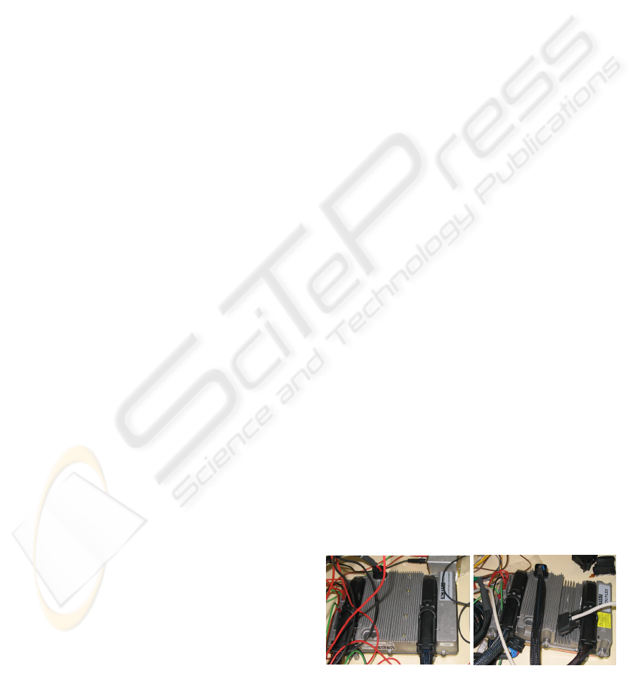
The French firm ACTIA supplies the chassis and
body modules used in this design. There are master
modules or CAMUs (Central Management Units)
and slave modules or IOUs (Input/Output Units) and
are shown in figure 3. These modules have several
inputs and outputs of different types and implement
the CAN V2.0 B protocol. These modules must be
ready to work in the conditions of a vehicle in
motion. Thus, the protection level must be high
(IP65) and must endure the vibrations and fulfil the
electromagnetic compatibility standards.
CAMU
IOU
Figure 3: Chassis and body modules.
VEHICULAR ELECTRONIC DEVICES CONNECTED BY ONBOARD FIELDBUS TECHNOLOGIES
7
3.2 Inputs and Outputs
The first step in the design is the identification of the
electrical signals of the bus that must be connected
to the networked control system. These signals must
be described in detail with their location in the bus.
Some of the signals included in the control system in
the Scania bus of the project are listed in table 1.
The signals are named according to a specified
format. The first part of the name defines some
characteristics of the signal. Some prefixes used in
Table I are: IB (Input Binary) and OB (Output
Binary). For example, the signal IB_STOPREQ is a
binary (B) input (I) that is activated when a stop is
requested. The column type shows additional
information about the signals. For inputs, VBAT or
GND active indicates whether the signal when
activated is connected to the power supply or to the
ground. For outputs there can be types like: signal
(digital signals not intended for powering devices),
lights, inductive (protection needed against power
peaks), valve, etc.
Once the signals have been defined, the next step
is to choose the number of required CAMUs and
IOUs, their location in the bus and where the
electrical signals will be connected (the connector
pin of a specific CAMU or IOU). The designer must
bear in mind the different types of inputs and outputs
of the modules. The CAMUs and IOUs have the
following types of inputs and outputs:
Table 1: Some electrical z in the SCANIA city-bus.
Name Type I/O Power
IB_MSDOOR1 VBAT
ACTIVE
Input -
IB_MSDOOR2 VBAT
ACTIVE
Input -
IB_MSDOOR3 VBAT
ACTIVE
Input -
IB_STOPREQ VBAT
ACTIVE
Input -
IB_RAMPREQ VBAT
ACTIVE
Input -
IB_HANDBRAKE GND
ACTIVE
Input -
IB_ALTERNATOR VBAT
ACTIVE
Input -
IB_SMCSEC CAN Input -
OB_REARMDOOR1 VALVE Output 25 W
OB_DOOR1 SIGNAL Output -
OB_DOOR2 SIGNAL Output -
OB_DOOR3 SIGNAL Output -
OB_POSLIGHTS1 LIGHTS Output 25 W
OB_ENGINEON INDUCTIVE Output 240 W
OB_HANDBRAKEBUZZ INDUCTIVE Output 3 W
- Wake up inputs:
The signals that should wake up the system
are connected in these inputs.
- Logic inputs:
The detection of a “0” logic is from 0 V up to
1.8 V, and a “1” logic from 7 V up to 32 V.
- Analog inputs to ground:
The voltage in the input of the
microprocessor is directly proportional to the
value of the resistive load.
- Analog inputs to positive voltage:
These inputs consist in a resistive divisor.
- Frequency inputs:
These inputs can be used for PWM signals, as
for example the measurement of speed.
- High state and low state outputs:
The maximum direct current of these outputs
can be 9 A, 7 A, 5 A, 3.2 A, 2 A and 1.5 A.
- Free wheel diode output:
It is dedicated to inductive loads (relays,
electro valves) as for example wiper fast.
- Switched and unswitched outputs:
The power supply of the output interface of
high state signals can be unswitched
(connected directly to the battery) or switched
(connected after the master relay).
- PWM (Pulse Wide Modulation) outputs:
There are several outputs that can be used for
PWM (0-100% with 10% step) or frequency
(50-500 Hz with 50 Hz step) outputs.
- Bridge outputs:
They are used for bidirectional motors
(electrical windows, external wing mirror,
etc.) or for current measurements.
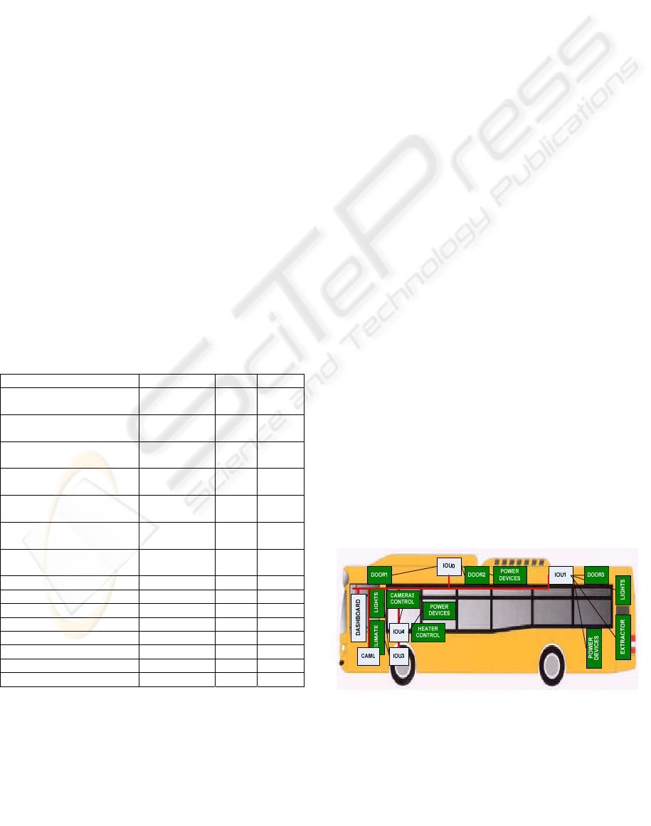
The number of CAMus and IOUs must be choice
taking into account the distribution of the signals in
the bus and also the power consumption, because the
modules define the maximum dissipated power by
group of outputs, the maximum total dissipated
power and the maximum permanent current.
Therefore, 1 CAMU and 4 IOUs have been required
in this design. The location of the modules and the
distribution of the signals are shown in figure 4.
Figure 4: Structure of the networked control system
onboard the bus.
ICINCO 2007 - International Conference on Informatics in Control, Automation and Robotics
8
3.3 Software Tools
There are several software tools used for the coding
of the modules, validation and their installation:
ActiGRAF (the wiring definition and inputs/outputs
assignment), ISaGRAF (the functions specification),
Multitool (diagnostic of the ECUs and CAN nodes)
and Telemux (programming the ECUs).
For the design of a networked control system,
ActiGRAF is the project manager and ISaGRAF is
the programming environment. Thus, ISaGRAF is a
tool used for ActiGRAF for developing the
embedded software in the CAN modules of the
control system. ISaGRAF supports the whole
programming languages of the IEC 61131 standard.
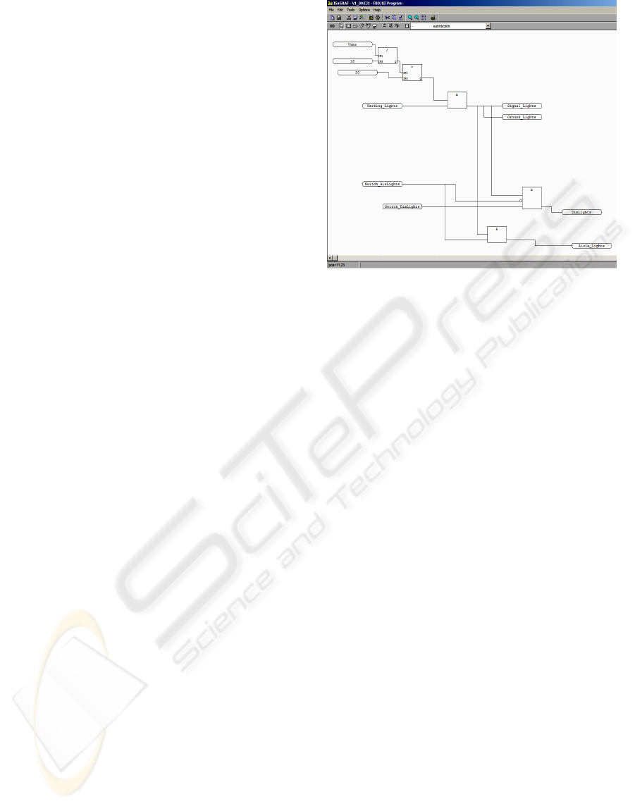
An example of how the specification and
implementation of functionality is made using
Function Block Diagram (FBD) programming
language is shown in figure 5. The user indicates the
activation condition of the outputs depending on the
state of the inputs with typical function blocks.
Figure 5 shows a programming example where the
aisle lights of the bus are switched on if there is
battery voltage higher than 20 V (the master relay
has been activated), the parking lights are turned on
and the switch of the aisle lights is activated.
When the user designs the networked control
system of a bus, the ActiGRAF tool is used to
specify the central network of the vehicle (all the
master modules or CAMUs), the intra-system
network (all the slave modules or IOUs), the inter-
system network and other networks that can be
necessaries according to the requirements for the
electrical architecture of the vehicle. After, the
opening of the communication ports should be made
(enable the CAN and J1939 drivers) and the input
and output signals should be declared. The
ISaGRAF tool is used to define the whole
functionalities of the chassis and body functions of
the bus using the more adequate programming
language of the above mentioned.
Once the whole functionality and the wiring are
defined, it is necessary to build the application that
will be executed inside the modules. ActiGRAF uses
a C compiler for compiling the source code
generated by ISaGRAF. The compiler used for these
tasks is from the Keil Company. The used version is
for the C166 platform along with the RTX166. The
binary code generated by the compiler is loaded
using the Telemux application. Only the CAMU is
reprogrammed with the binary code. As soon as the
system is restarted, the CAMU automatically sends
the new application and wiring data to all the IOUS
of the system.
Figure 5: Example of the specification of a function in a
bus using the ISaGRAF tool.
4 FUTURE WORKS
The authors are working in the design and
implementation of new communication modules to
improve the multiplexed networks used currently in
city public transport buses. These modules should
integrate all the sensors and actuators in an optimum
way. Besides, these modules must resolve those
particular functions that are not integrated in the
multiplexed solutions of the chassis manufacturers.
These new communication modules will be
designed using reconfigurable circuits technology as
for example FPGAs (Lías, 2000). The
implementation of communication processors for
fieldbuses using FPGAs has a lot of advantages on
account of their reconfiguration ability (Valdés,
2004).
The modules will be designed to enable the
integration of the whole functions existent in the
public transport buses and to add other new ones that
are interesting for the coachbuilder such as closed-
circuit TV, infrared control for doors, modules with
outdoor connection, etc.
All these new functions must be integrated in the
driver display. Thus, it is interesting the
development of a system to integrate in the
dashboard of the city-buses a PDA with the VDV
protocol and that complements the information of
the display included in the dashboard. The PDA
could be integrated in the CAN networked control
system using a VDV node that transmits the
information to the PDA using a Bluetooth link. The
VDV module can be designed with a FPGA that
VEHICULAR ELECTRONIC DEVICES CONNECTED BY ONBOARD FIELDBUS TECHNOLOGIES
9

implements the CAN protocol in accordance to the
J1939 standard and that manage the communication
of a simple Bluetooth device (Flooks, 2005).
Other important improvement to be taking into
account in the design of these modules is the
possibility of integration of the localization and fleet
management systems by GPRS, GSM, radio, etc.
The integration of these systems enables the
localization of the vehicles from the head office, the
automation of the displaying systems for driver and
passengers, the notification of next stop, estimated
time to arrive to the bus stop, etc.
5 CONCLUSIONS
The main objectives of the work exposed in this
paper is the improvement of the control system
onboard the public transport buses. The authors
design a networked control system based on
modules with CAN communication. Thus, the
advantages of this system used to integrate the
electronic devices in a real time and reliable
information system are:
- Development of a networked control system
that satisfies the maximum demands of any
public transport enterprise.
- Reduction of cables and number of electrical
components (relays, fuses, etc.).
- Unification of the electronic equipment.
- The system has a central memory for the
registration of alarms and maintenance.
- Autodiagnostic of the system.
- Improvements in the vehicle working control
and the maintenance management.
- Improvements in the comfort.
- Best reliability of the components.
- Less maintenance costs.
- A flexible and modular system is obtained.
The design of modules based on FPGAs and
fulfilling the J1939 standard and the VDV
recommendation 234 is a very interesting solution
for the coachbuilders. Accordingly, they can have
their own CAN networked control systems and
install in the public transport buses their own
compatible devices to control the different chassis
and body functionalities.
ACKNOWLEDGEMENTS
This work has been sponsored by an R&D project
from the Autonomous Government (Galicia, Spain),
Ref.PGIDIT05TIC011E. This work has been made
in collaboration with the coachbuilder enterprise
Castrosua S.A. and the Actia S.A. Company.
REFERENCES
Bender, M., September 2004. Introducing the MLX4: a
microcontroller for LIN. EDN Europe, pp. 22-26.
Bosch, September 1991. CAN specification Version 2.0,
Robert Bosch GmbH.
Domínguez, M.A., Mariño, P., Poza, F., Otero, S., 7-10
November 2006. Industrial communication system in
technology control for public transport vehicles. In
Proceedings of 32
nd
Annual Conference of IEEE
Industrial Electronics Society (IECON´06), ISBN 1-
4244-0136-4, pp. 585-590.
Estevez, M., October 2004. MOST and MPEG: a perfect
relationship?. Embedded Systems Europe, pp. 36-38.
Flooks, S., June 2005. Putting EDR to the test. Electronic
Design Europe, pp. 8-9.
ISO 11898, 1992. Road Vehicles – Interchange of digital
information – Controller Area Network for high-speed
communication, ISO.
ISO 11519-2, 1995. Road Vehicles – Low-speed serial
data communication – Part 2: Low-speed Controller
Area Network (CAN), ISO.
Lías, G., Valdés, M.D., Domínguez, M.A., Moure, M.J.,
September 2000. Implementing a fieldbus interface
using a FPGA. LNCS 1896, Springer-Verlag, pp. 175-
180.
Mariño, P., 2003. Enterprise communications: Standards,
networks and services, Ed. RA-MA. Madrid, second
edition.
Marsh, D., September 1999. Automotive design sets
RTOS cost performance challenges. EDN, pp. 32-42.
Marsh, D. (editor), July 2005. Engines of change, EDN
Europe, pp. 58-73.
SAE J1939, Revised January 2005. Surface Vehicle
Recommended Practice, SAE.
Valdés, M.D., Domínguez, M.A., Moure, M.J., Quintáns,
C., September 2004. Field Programmable Logic and
Applications: A reconfigurable communication
processor compatible with different industrial
fieldbuses. Lecture Notes in Computer Science 3203,
Springer-Verlag, pp. 1011-1016.
Verband Deutscher Verkehrsunternehmen (VDV), June
1996. Driver’s Workplace in the Low-Floor Line-
Service Bus – Recommendation 234, ISO/TC 22/SC
13/WG 3 N226.
ICINCO 2007 - International Conference on Informatics in Control, Automation and Robotics
10
