
ROBUST AND STABLE ROBOTIC FORCE CONTROL
Michael Short
1
and Kevin Burn
2
1
Embedded Systems Laboratory,University of Leicester, UK.
2
Control Systems Centre, University of Sunderland, UK
Keywords: Robotic force control, model following control, stability.
Abstract: To perform many complex tasks, modern robots often require robust and stable force control. Linear, fixed-
gain controllers can only provide adequate performance when they are tuned to specific task requirements,
but if the environmental stiffness at the robot/task interface is unknown or varies significantly, performance
is degraded. This paper describes the design of a robotic force controller that has a simple architecture yet is
robust to bounded uncertainty in the environmental stiffness. Generic stability conditions for the controller
are developed and a simple design methodology is formulated. The controller design is tested on an
experimental robot, and is shown to perform favourably in the presence of large changes in environmental
operating conditions.
1 INTRODUCTION
Traditionally, most industrial robots are designed to
allow accurate and repeatable control of the position
and velocity of the tooling at the device’s end
effector. However, if robots are to perform complex
tasks in a wider range of applications in the future, it
will be essential to accurately control forces and
torques at the end effector/task interface. In addition,
task constraints sometimes require position control
in some degrees-of-freedom (DOF), and force
control in others. Thus, to fulfil these extra demands,
an important area of robotics research is the
implementation of stable and accurate force control.
However, this is often difficult to achieve in
practice, particularly where robots are operating in
unpredictable or disordered environments.
A large number of force control techniques of
varying complexity have been proposed over the last
twenty years (Zang & Hemami 1997; Whitney
1985). The most basic direct methods simply
transform joint-space torques into a Cartesian-space
wrench, either in an open-loop fashion (which do not
require the explicit measurement of forces and
torques) or using inner and outer closed loops for
accurate control of joint torques and Cartesian
forces, respectively. However, since most industrial
robots have position control loops that are not easily
modified, indirect methods are often preferred.
These involve modifying either joint or Cartesian
position demands in order to control forces by
deliberately introducing position control errors and
using the inherent stiffness of the manipulator in
different Cartesian directions. Alternatively, it is
possible to add an outer force control loop in
systems that have a facility for real-time path
modification (Bicker et al. 1994).
Two major problems in the implementation of
practical controllers are stability and robustness.
Stable force control is particularly difficult to
achieve in ‘hard’ or ‘stiff’ contact situations, where
the control loop sampling rate may be a limiting
factor. In an attempt to improve stability various
methods have been proposed, the simplest being the
addition of compliant devices at the robot wrist
(Whitney & Nevins 1979). Another solution is to
employ ‘active compliance’ filters, where force
feedback data is digitally filtered to emulate a
passive spring/damper arrangement (Kim et al.
1992). However, both methods introduce a
potentially unacceptable lag. Robustness is a
problem where environmental uncertainty exists,
and effective force control can only be achieved by
employing an accurate environment stiffness
detection technique and smooth switching between
controller gains (Ow 1997). This slows down task
execution, and can result in unstable contact when
the effective stiffness at the robot/environment
interface (K
e
) varies significantly.
Recent increases in processing power of low-
cost computers has led to an increased interest in
‘intelligent control’ techniques such as those
256
Short M. and Burn K. (2007).
ROBUST AND STABLE ROBOTIC FORCE CONTROL.
In Proceedings of the Fourth International Conference on Informatics in Control, Automation and Robotics, pages 256-261
DOI: 10.5220/0001618302560261
Copyright
c
SciTePress
employing fuzzy logic, artificial neural networks and
genetic algorithms (Linkens & Nyongsa 1996).
Where attempts have been made to employ these
techniques (specifically fuzzy logic) in explicit robot
force controllers, simulation studies have
demonstrated good tracking performance despite
wide variations in environment stiffness, e.g.
(Tarokh & Bailey 1997; Seraji 1998), and for
specific contact situations, e.g. deburring (Kiguchi &
Fukuda 1997). Improved performance using a
hierarchical fuzzy force control strategy has also
been demonstrated for various contact situations,
such as peg-in-hole insertion (Lin & Huang 1998).
However, fuzzy techniques are not without
problems. In addition to problems associated with
dimensionality, i.e. large numbers of rules that must
be evaluated in the inference process, the
performance and stability of fuzzy systems are often
difficult to validate analytically (Cao et al. 1998;
Wolkenhauer & Edmunds 1997). Additionally, when
compared to more ‘traditional’ control methods such
as LQR (Frankin et al. 1994), the resulting fuzzy
designs are more complex, have larger memory
requirements and larger execution times (Bautista &
Pont 2006).
Recent years have seen increased interest in the
use of model following control (MFC) techniques.
Due to its conceptually simple design and powerful
robustness properties, this type of controller has
been found to be particularly suited to industrial
applications such as robotics and motion control
(e.g. Li et al. 1998; Osypiuk et al. 2004). As such, it
would seem that MFC-based techniques may prove
to be applicable in the force control domain. This
idea shall be explored in this paper, and a simple and
stable MFC-based technique for force control is
presented.
The paper is organised as follows. Section 2
presents a short overview of common difficulties in
practical robotic force control. Following this,
Section 3 gives a brief description of the MFC-based
force controller, and generic stability conditions are
developed. In section 4 this technique is applied to a
robotic test facility and results are presented. Finally,
conclusions and suggestions for further work are
outlined.
2 FORCE CONTROL
Prior to examining the robust approach, it is
beneficial to outline the force control problem under
consideration and describe a conventional solution.
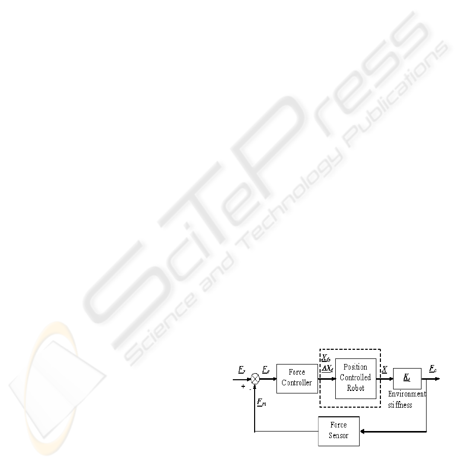
A typical conventional force control scheme is
shown in Figure 1. The combined stiffness at the end
effector/task interface in the direction of the applied
force is K
e
. This varies between a minimum value,
determined by the objects in the environment with
which the robot is in contact, and a maximum value,
limited by the stiffness of the arm and torque sensor.
The latter is dominant when the robot is touching a
surface of very high stiffness, i.e. in a hard contact
situation. Designing a fixed-gain conventional
controller to meet a chosen specification for a
specific value of K
e
is, in principle, a relatively
straightforward task. A problem arises when K
e
is
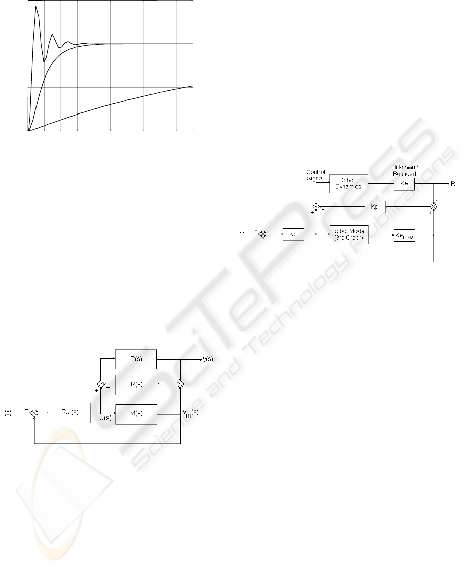
unknown or variable, as shown in Figure 2. For
example, consider the case where the system is
tuned to achieve a specified performance at an upper
limit of K
e
- at low K
e
the system will be
overdamped with a relatively high settling time.
Conversely, if the system had been tuned for the
desired performance at the lower limit of K
e
,
significant overshoot and oscillatory behaviour
would have occurred at higher stiffness values.
In practical robotic systems these effects often
have serious consequences, mainly in relation to
system stability. In particular, the finite and
relatively low sampling rates of many industrial
robot control systems can result in unstable
behaviour, a situation exacerbated by the presence of
noise, non-linearities and other factors. For this
reason, force controllers of the type described
usually require some form of environment stiffness
detection technique to enable the controller gains to
be switched accordingly. The main problem with
this process is that it is time consuming, often
involving ‘guarded moves’ to contact in order to
enable sufficient data to be collected for the
algorithm to work. Such methods can also be
unreliable in the presence of transducer noise, and
are not very effective in situations where K
e
is
variable or rapidly changing.
Figure 1: Robot force control.
ROBUST AND STABLE ROBOTIC FORCE CONTROL
257
0
1.0
1.5
Time
(
s
)
Force
(
N
)
0.5
0.2 0.4 0.6 0.8 1.0
Hard contact, system tuned
for low K
e
Soft contact, system tuned
for high K
e
Tuned response
Figure 2: Effect of environmental stiffness.
3 ROBUST FORCE CONTROL
3.1 Principle
In this section we present the proposed robust force
controller. It is loosely based around the robust PID
strategy discussed in detail by Scokzowski et al.
(2005). The original strategy is based upon a two-
loop MFC, containing a nominal model of the
controlled plant and two PID controllers. The block
diagram of a basic MFC controller is shown in
Figure 3.
Figure 3: Robust PID based on MFC.
In this type of control, the model compensator
R
m
(s) is tuned to a nominal model of the plant M(s);
the actual plant P(s) contains bounded uncertainties.
The auxiliary controller R(s) acts on the difference
between the actual process output and the model
process output to modify the model control signal
u
m
(s), which is also fed to the plant.
As shown in Figure 1, when adding an outer
force control loop, it is common to use a velocity
signal as the input to the robot. In this case the
model M(s) is simply the second order motion
control loop dynamics augmented by a free
integrator, and a known value of environment
stiffness. The bounded uncertainty in the plant is
then just the environment stiffness K
e
, varying
between Ke
max
and Ke
min
.
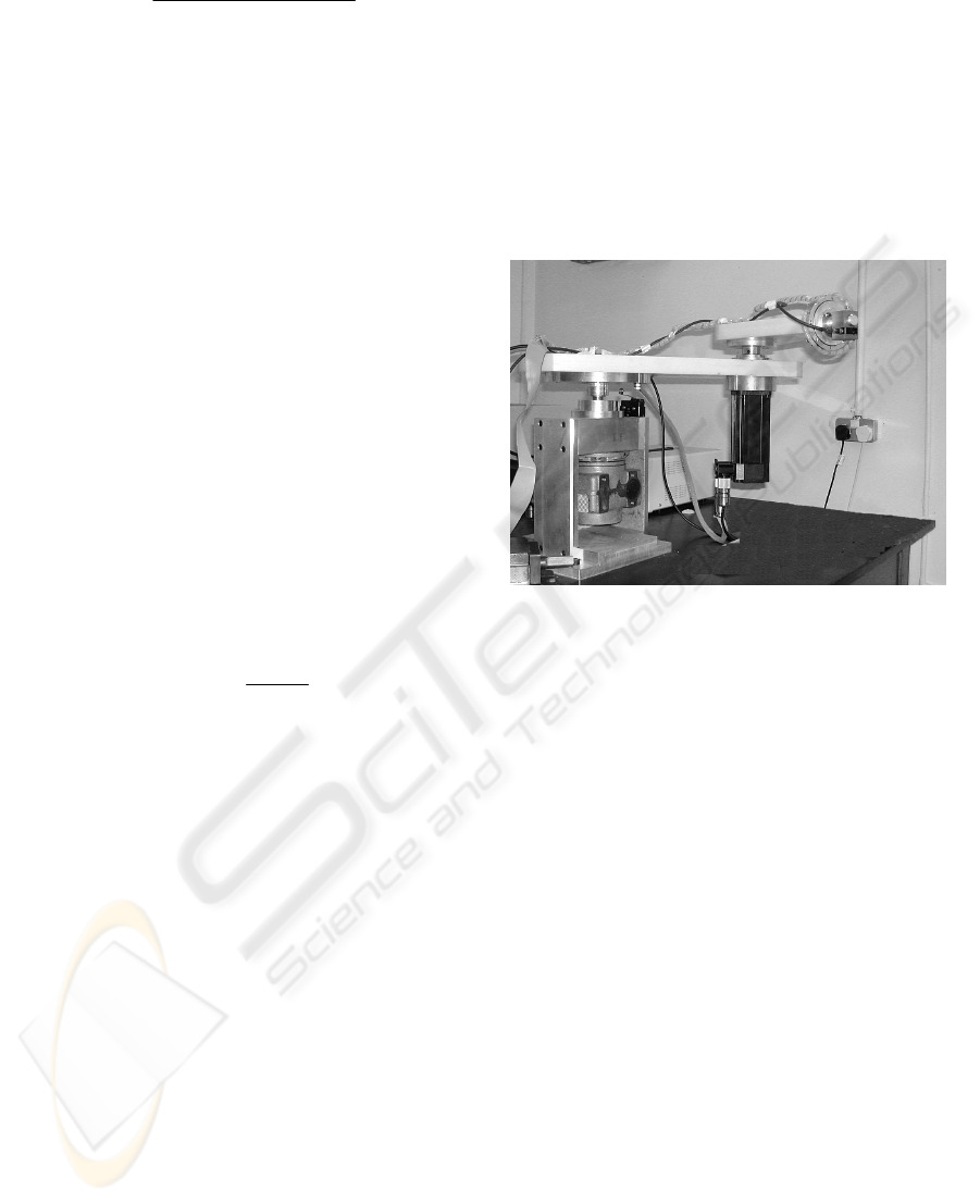
If the two loop controllers R(s) and R
m
(s) are
simple proportional gains, as shown in Figure 4,
then the MFC structure is considerably simplified.
The model loop gain Kp can be tuned for Ke
max
, (a
relatively trivial task) whilst the auxiliary loop gain
Kp’ can be tuned to provide an additional control
signal should the actual value of K
e
be less than
Ke
max
. In the following section we will consider the
stability criteria for this controller structure and
provide a bound on the maximum value for Kp’.
Figure 4: Robust force controller.
3.2 Design for Stability
If the ‘model loop’ controller R
m
(s) is tuned for
stability using a nominal design method on the plant
P(s) augmented by the maximum environmental
stiffness gain Ke
max
, then we know that the stability
of the overall control strategy is restricted by the
roots of the equation:
0)](1)[()(1 =Δ+
+
ssMsR
(1)
Where Δ(s) denotes the model perturbations
(uncertainty). The objective is to find for a given
plant and bounded uncertainty in the stiffness gain a
maximum bound on |R(s)| that will maintain
stability. In the case where the uncertainty
exclusively resides in the environment stiffness gain
K
e
, then if the original loop is tuned for Ke
max
then
M(s)[1+Δ(s)] in (1) reduces to:
max
)()()](1)[(
e
KsGsPssM =
=
Δ
+
(2)
The robot dynamics have the form (due to the
free integrator in the forward path):
ICINCO 2007 - International Conference on Informatics in Control, Automation and Robotics
258
sss
sG
nn
n
2
23
2
2
)(
ωξω
ω
++
=
(3)
And the controller R(s) in this case is a single
gain, Kp’, using (2) and (3) we can re-write equation
(1) as follows:
0'2
max
22
23
=+++ KeKpsss
nnn
ωωξω
(4)
Applying the Routh-Hurwitz stability criterion
(Pippard 1997) for a cubic equation, we know that
the system is stable if all the co-efficients in the left
of (4) are positive, and the following criterion is
satisfied:
max
22
'2 KeKp
nnn
ωωξω
≥
(5)
Re-arranging (5) gives a stability limit for the
controller gain Kp’
max
as follows:
max
max
2
'
Ke
Kp
n
ξω
=
(6)
Thus if the gain Kp’ is chosen between the
limits:
max
'' KpKpKp <<
(7)
The controller will be stable for unknown
environment gains in the range 0 < K
e
< K
emax
; as for
all gains below Ke
max
, the stability criteria of (5)
holds.
4 EXPERIMENTAL TESTING
4.1 Test Facility
A research facility, previously described in detail
(Short 2003), has been developed in the form of a
planar robot arm and PC-based open architecture
controller. The robot joints are actuated by brushless
servomotors (with digital servoamplifiers), and the
control loop for each axis is closed via a
multitasking DSP embedded in a Delta Tau®
Programmable Multi-Axis Controller (PMAC)
motion control card, installed into the PC
Each axis has an individual PID controller with
feedforward control to enable accurate velocity and
position profile following. A six-axis force/torque
sensor was developed in-house for the project, and
used in this study. The robot arm is shown in Figure
5. For this work, a one-axis version of the system
was employed by attaching the sensor to the wrist of
the second link, which was then locked at 90° to the
first link.
Figure 5: Test facility.
In this paper, we apply the controller proposed in
the previous section to this facility. The controller
was coded in C and added into the control library.
Each experiment involved a contact situation, where
the robot first approached a surface then applied a
force of 25 N. The contact surface was varied in
each experiment, and we used two surfaces; hard
(steel) and soft (plastic). In order to reliably detect
the contact surface, the end effector was fitted with a
Baumer Electric® photoswitch which was calibrated
to signal with high accuracy when an object was
5mm away. The robot thus approached the contact
surface at a slow jog speed until this signal was
made, then switched to force control mode. The
sample rate was 200 Hz in each experiment. In the
following section we describe the parameters that
were used.
4.2 Controller Design
From a previous identification exercise, the
parameters of the robot arm model and the
environment stiffness limits were determined to be
as follows (Short 2003):
ROBUST AND STABLE ROBOTIC FORCE CONTROL
259
mmNKmmNK
srad
ee
n
/11,/168
,1,/244
minmax
==
=
=
ξ
ω
(8)
Using these parameters, the nominal loop gain
Kp was tuned to a value of 0.02 to give the desired
transient performance – a 95% rise time of
approximately 2 seconds with minimal (ideally zero)
overshoot. Using (6), Kp’
max
was determined to be
2.9. We therefore chose a value of Kp’ = 1.5 for the
experiments.
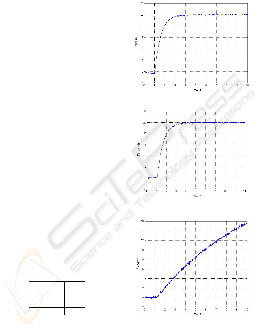
4.3 Experimental Results
Figure 6 shows the response of the system when
applying a force to the hard (steel) surface. The very
small negative force indicated before contact with
the surface was made (at approx 1s) was due to a
small drift in the calibration of the force sensor
whilst moving in free space. Figure 7 shows the soft
(plastic) case. We also show, for completeness, the
contact situation for a single loop controller tuned
for high K
e
in the soft contact case. This is shown in
figure 8.
These figures demonstrate the effectiveness of
the approach. Comparing Figures 7 and 8, the
compensation added by the extra loop can clearly be
seen; in Figure 7 we see an almost identical transient
to Figure 6. Additionally, in Figure 6 the controller
demonstrates no signs of instability as Kp’ was kept
below the maximum amount. We also measured the
integral of time by absolute error ITAE (Franklin et
al. 1994) for the responses shown in Figures 6, 7 and
8. This is shown in Table 1. From this the closeness
of the proposed robust controller transient responses
can be seen (R). The response of the normal (N)
controller is also shown in the table. The poor
quality of control is clearly highlighted by this vastly
increased value.
Table 1: ITAE measures for contact situations.
System ITAE
(R) Low K
e
23.61
(R) High K
e
23.95
(N) Low K
e
666.5
Figure 6: Hard contact situation.
Figure 7: Soft contact situation.
Figure 8: Soft contact situation (normal controller).
ICINCO 2007 - International Conference on Informatics in Control, Automation and Robotics
260

5 CONCLUSIONS
In this paper a distinct method for robotic force
control has been proposed and tested using an
experimental test robot. The method has been shown
to improve system performance where a high degree
of environmental uncertainty exists, without the
need for a stiffness detection routine. The method is
conceptually simple and extremely easy to
implement; its simplicity also lends itself to easy
analytical analysis.
The practical realisation of robotic force control
remains a problematic area of research. However,
the potential of simple, stable controllers to
overcome fundamental difficulties associated with
applications where environmental uncertainty exists
has been demonstrated.
However, work is required to further validate the
control method. This will include analysis of
situations where PD controllers are used as the loop
compensators, and forces are applied in Cartesian
coordinates. We will also consider the effects of
model mismatch (which is inevitable if the
methodology is to be applied to industrial robots).
Further work will also consider implementation on a
6-DOF manipulator to confirm its performance in a
range of industrial tasks, and to contrast the
approach with other methodologies.
REFERENCES
Bautista, R., Pont, M.J., 2006. Is fuzzy logic a practical
choice in resource-constrained embedded control
systems implemented using general-purpose
microcontrollers? In Proceedings of the 9th IEEE
International Workshop on Advanced Motion Control,
Istanbul, Volume 2, pp.692-697.
Bicker, R., Burn, K., Glennie, D., Ow, S.M., 1994.
Application of force control in telerobotics. Proc Int
Conf EURISCON '94, Malaga, Spain.
Cao, S.G., Rees, N.W., Feng, G., 1998. Lyapunov-like
stability theorems for continuous-time fuzzy control
systems, Int J Control. Vol. 69(1), pp. 49-64.
Franklin, G.F., Powell, J.D., Emani-Naeini, A., 1994.
Feedback Control Of Dynamic Systems. Addison-
Wesley Publishing, Reading Massachusetts, third
edition.
Kiguchi, K., Fukuda, T., 1997. Intelligent position/force
controller for industrial robot manipulators –
application of fuzzy neural networks. IEEE Trans
Industrial Electronics, Vol. 44(6), pp. 753-761.
Kim, W.S., Hannaford, B., Bejczy, A.K., 1992. Force
Reflection and Shared Compliant Control in Operating
Telemanipulators with Time Delay. IEEE Trans on
Robotics and Automation, Vol. 8(2), pp. 176-185.
Li, G., Tsang, K.M., Ho, S.L., 1998. A novel model
following scheme with simple structure for electrical
position servo systems. Int. J. Syst. Sci., Vol. 29, No.
9, pp. 959–969.
Lin, S.T., Huang, A.K., 1998. Hierarchical Fuzzy Force
Control for Industrial Robots. IEEE Transactions on
Industrial Electronics, Vol. 45, No. 4, pp. 646-653.
Linkens, D.H., Nyongesa, H.O., 1996. Learning systems
in intelligent control: an appraisal of fuzzy, neural and
genetic algorithm control applications. IEE Proc
Control Theory Appl, Vol. 143(4), pp. 367-386.
Osypiuk, R., Finkemeyer, B., Wahl, F.M., 2004. Forward-
model based control system for robot manipulators.
Robotica, Vol. 22, No. 2, pp. 155–161.
Ow, S.M., 1997. Force Control in Telerobotics. PhD
Thesis, University of Newcastle upon Tyne, UK.
Pippard, A.B., 1997. Response & Stability: An
Introduction to the Physical Theory. Cambridge
University Press.
Seraji, H., 1998. Nonlinear and Adaptive Control of Force
and Compliance in Manipulators. Int J Robotics
Research, Vol. 17(5) pp. 467-484.
Short, M., 2003. A Generic Controller Architecture for
Advanced and Intelligent Robots. PhD. Thesis,
University of Sunderland, UK.
Skoczowski, S., Domek, S., Pietrusewicz, K., Broel-Plater,
B., 2005. A Method for Improving the Robustness of
PID Control. IEEE Transactions On Industrial
Electronics, Vol. 52, No. 6.
Tarokh, M., Bailey, S., 1997. Adaptive fuzzy force control
of manipulators with unknown environment
parameters. J Robotic Sys, Vol. 14(5), pp. 341-353.
Whitney, D.E., 1985. Historical Perspective and State of
the Art in Robot Force Control.
Int J Robotics Res,
Vol. 6(1), pp. 3-14.
Whitney, D.E., Nevins, J.L., 1979. What is the Remote
Centre Compliance (RCC) and what can it do? Proc
Int Symp on Industrial Robots, Washington DC, pp.
135-152.
Wolkenhauer, O., Edmunds, J.M., 1997. A critique of
fuzzy logic in control. Int J Electrical Engineering
Education, Vol. 34(3), pp. 235-242.
Zhang, G., Hemami, A, 1997. An Overview of Robot
Force Control. Robotica, Vol. 15, pp. 473-482.
ROBUST AND STABLE ROBOTIC FORCE CONTROL
261
