FORMAL VERIFICATION OF SAFETY BEHAVIOURS OF THE
OUTDOOR ROBOT RAVON
Martin Proetzsch, Karsten Berns
Robotics Research Lab, University of Kaiserslautern, Germany
T. Schuele, K. Schneider
Reactive Systems Group, University of Kaiserslautern, Germany
Keywords:
Behaviour-based control, formal verification, outdoor robotics.
Abstract:
This paper presents an approach to the formal verification of safety properties of the behaviour-based control
network of the mobile outdoor robot RAVON. In particular, we consider behaviours that are used for the com-
putation of the projected vehicle’s velocity from obstacle proximity sensor data and inclination information.
We describe how this group of behaviours is implemented in the synchronous language Quartz in order to
be formally verified using model checking techniques of the Averest verification framework. Moreover, by
integrating the automatically generated and verified code into the behaviour network, it can be guaranteed that
the robot slows down and stops as required by the given safety specifications.
1 INTRODUCTION
More and more applications like unmanned space
travelling, autonomous farming, civil protection, and
humanitarian demining require autonomous vehicles
navigating in unstructured natural terrain. The di-
versity as well as missing information for physical
models of outdoor scenarios call for a flexible con-
trol architecture not requiring a complete knowledge
of the environment to achieve robust locomotion. In
this context, behaviour-based control networks have
proven suitable for appropriate reaction on external
influences.
One of the advantages of behaviour-based ar-
chitectures is emergence: The combination of be-
haviours leads to proper reactions not directly ex-
plainable by the individual components. On the other
hand, this feature also poses problems concerning
predictability, making it difficult to reason about the
correctness of the overall system. However, safety
critical applications require proofs that guarantee that
given specifications are met. In particular, the correct-
ness of reactive control layers is mandatory for the fi-
nal behaviour of the robot.
In circuit design, formal verification has already
become a standard to avoid design errors. Since
all possible input traces of a system are considered
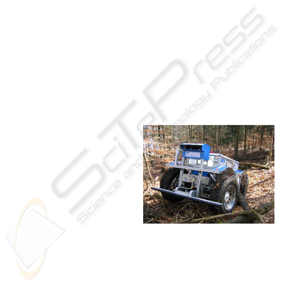
Figure 1: RAVON in rough outdoor terrain.
by formal verification methods, it is guaranteed that
the checked specifications hold under all circum-
stances. In particular, different kinds of model check-
ing (Schneider, 2003; Schuele and Schneider, 2006)
are popular verification methods due to the high de-
gree of automation.
In this paper, we consider the formal verifica-
tion of a part of the behaviour-based control network
of the mobile outdoor platform RAVON (Robust
Autonomous Vehicle for Off-road Navigation, see
Fig. 1), namely RAVON’s control system that is re-
157
Proetzsch M., Berns K., Schuele T. and Schneider K. (2007).
FORMAL VERIFICATION OF SAFETY BEHAVIOURS OF THE OUTDOOR ROBOT RAVON.
In Proceedings of the Fourth International Conference on Informatics in Control, Automation and Robotics, pages 157-164
DOI: 10.5220/0001619101570164
Copyright
c
SciTePress
sponsible for slowing down and stopping the vehi-
cle. It is clear that this part is highly safety criti-
cal, and therefore, it is very important to guarantee
its correctness. To this end, we have implemented
this part of the behaviour-based control network in the
synchronous programming language Quartz (Schnei-
der, 2001b; Schneider, 2006). We then used the for-
mal verification methods of the Averest framework
(Schneider and Schuele, 2005) to check the correct-
ness of our implementation with respect to given
safety conditions.
The application of formal methods to verify the
correctness of a robot system is not new: In (Diethers
et al., 2003), the model checker HyTech was used to
analyse a robot program based on skill primitive nets.
While HyTech considers hybrid automata as system
models to model continuous values of physical prop-
erties, our approach is based on discrete transition
systems that benefit directly from symbolic model
checking techniques. The use of symbolic model
checking for the formal verification of a robot sys-
tem has been reported in (Sharygina et al., 2004). In
contrast to our approach, however, the verification is
not integrated with code generation.
The use of synchronous languages (Benveniste
et al., 2003) for the implementation of safety critical
control systems of robots is also not new: In (Sowmya
et al., 2002), a controller for a mobile robot (Rug
Warrior) has been implemented in the synchronous
language Esterel (Berry, 1998). In (Kim and Kang,
2005), the core of the Samsung Home Robot SHR100
has been re-engineered to be verified by means of
the Esterel framework. In contrast to our approach,
the systems considered in (Sowmya et al., 2002) and
(Kim and Kang, 2005) were quite small control pro-
grams with only a few control states.
In contrast to the previous work in this area, our
approach considers verification as well as (verified)
code generation. Moreover, the considered system is
not simply a small control program, but a behaviour-
based control network with difficult interdependen-
cies.
The outline of the paper is as follows: In the
next two sections, we give some details on the out-
door robot RAVON and its behaviour-based control
system. In Section 4, we describe the verification
framework Averest and give some basics about syn-
chronous languages and model checking. Section 5
contains the results of the verification. Finally, we
conclude with a summary and directions for future
work.
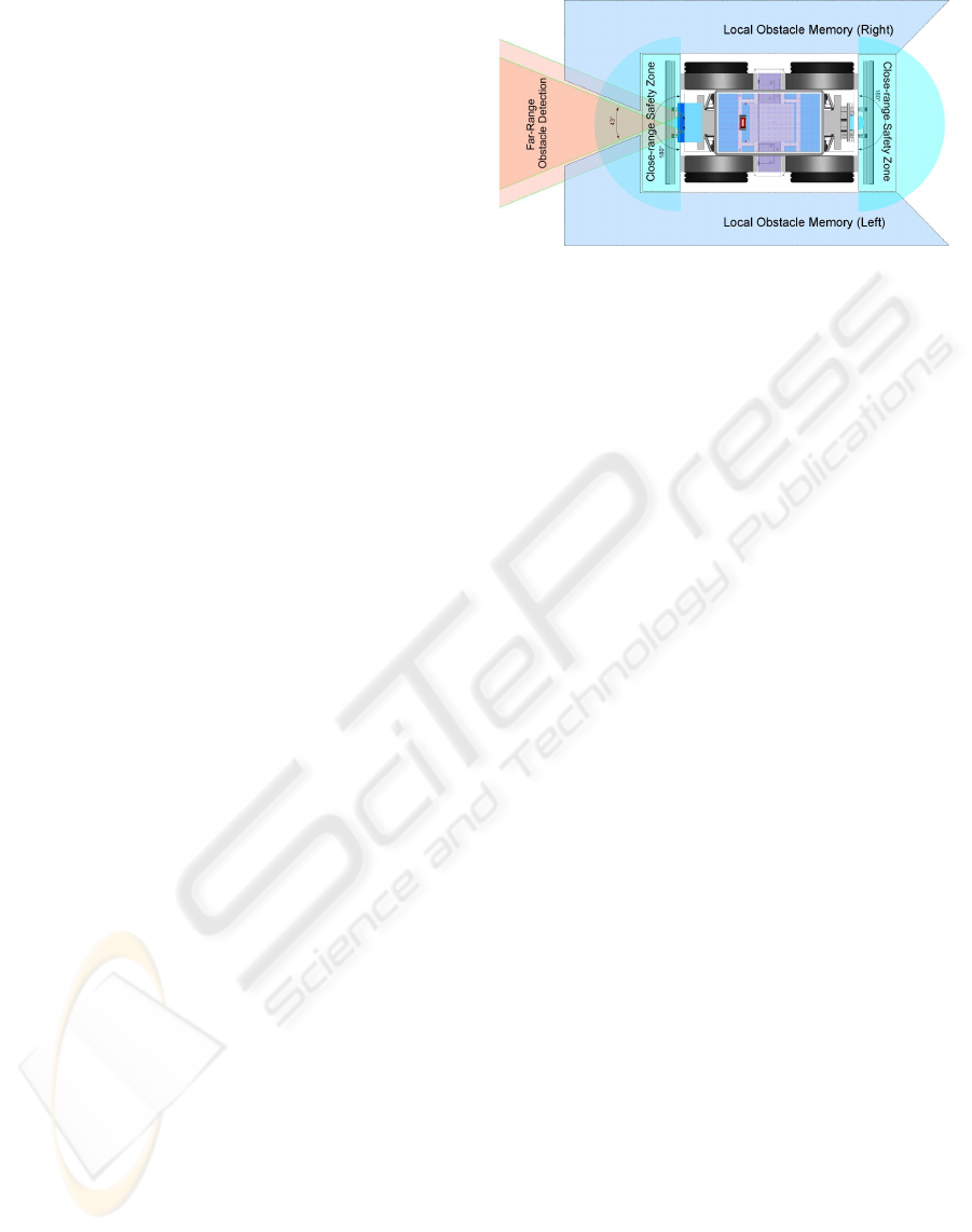
Figure 2: Regions monitored by the obstacle detection and
avoidance facilities.
2 THE OUTDOOR ROBOT
RAVON
RAVON is a four wheeled off-road vehicle measur-
ing 2.35 m in length and 1.4 m in width and weight-
ing 400kg. The vehicle features a four wheel drive
with independent motors yielding maximal velocities
of 3 m/s. In combination with its off-road tires, the
vehicle can climb slopes of 100% inclination predes-
tining it for the challenges in rough terrain. Front and
rear axis can be steered independently which supports
agile advanced driving manoeuvres like double Ack-
erman and parallel steering.
In order to navigate in a self-dependent fashion,
RAVON has been equipped with several sensors. For
self localisation purposes, the robot uses its odometry,
a custom design inertial measurement unit, a mag-
netic field sensor, and a DGPS receiver. The sensor
data fusion is performed by a Kalman filter (Schmitz
et al., 2006) which calculates an estimated pose in
three dimensions. Due to gravity measurements of the
inertial measurement unit, the control system receives
quite precise absolute data for the roll and pitch angle
of the vehicle. These are fed into behaviours that are
responsible for supervising whether the vehicle might
tip over due to critical inclination.
In order to protect the vehicle in respect to ob-
stacles, several safety regions are observed by dif-
ferent sensor systems (Sch
¨
afer and Berns, 2006) (see
Fig. 2). First of all, hindrances can be detected using
the stereo camera system mounted at the front of the
vehicle. The stereo camera’s narrow field of vision
is compensated by local obstacle memories to either
side of the robot realising a short-term representation
of detected obstacles. This obstacle detection facility
is complemented with two laser range finders (field
of vision: 180 degrees, angular resolution: 0.5 de-
grees, distance resolution: about 0.5 cm) monitoring
the environment nearby the vehicle. Data from both
sources of proximity data is used for obstacle avoid-
ICINCO 2007 - International Conference on Informatics in Control, Automation and Robotics
158
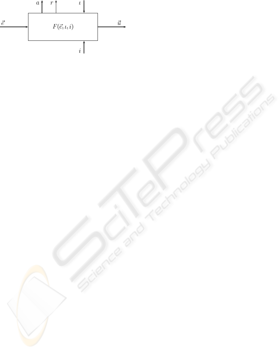
Figure 3: Basic behaviour module.
ance by appropriate behaviours, the fusion of which
is performed inside the behaviour network.In case of
emergency, the system is stopped on collision by the
safety bumpers which are directly connected to the
emergency stop to ensure maximal safety.
3 BEHAVIOUR-BASED
CONTROL SYSTEM OF RAVON
This section introduces the components used for
building up the behaviour-based network controlling
RAVON.
3.1 Behaviour Module
The fundamental unit of the proposed control archi-
tecture is the behaviour module (see Fig. 3). Each
atomic behaviour is wrapped into such a module with
a defined interface. Behaviours can be described as
three-tuples of the form
B = (r,a,F) (1)
where r is the target rating function, a is the activ-
ity function, and F is the transfer function of the be-
haviour. Additionally each behaviour receives an in-
put vector ~e, an activation ι, and an inhibition i and
generates an output vector~u.
More precisely behaviours receive data needed for
fulfilling their work via the sensor input~e ∈ ℜ
n
which
can be composed of sensory data or information from
other behaviours. The output vector ~u ∈ ℜ
m
trans-
mits data generated by the behaviour. This output
describes the influence a behaviour can have on the
environment or on other behaviours.
Each behaviour owns an input determining its ac-
tivation ι ∈ [0, 1]. In this notation ι = 0 indicates de-
activation and ι = 1 a fully activated behaviour. Val-
ues between 0 and 1 refer to a partially activated be-
haviour. Activation can be used to adjust the rele-
vance of competing behaviours. The inverse effect is
achieved by inhibition i ∈ [0,1] which is used to re-
duce the activation of a behaviour: i = 1 refers to full
inhibition, i = 0 to no inhibition.
Information about the activity of a behaviour is
provided by the output a ∈ [0, 1]. The maximal ac-
tivity is described by a = 1, inactivity by a = 0. It is
defined by the activity function
a(~e, ι,i) = a
int
(~e) · ι· (1− i) (2)
where a
int
(~e) ∈ [0, 1] is an internal function represent-
ing the intended activity of the behaviour.
The target rating r ∈ [0, 1] deals as an indicator
for the contentment of a behaviour. A value of r = 0
indicates that the behaviour is content with the actual
state, while r = 1 shows maximal dissatisfaction.
The output vector ~u of a behaviour is determined
using its transfer function F(~e,ι, i) where
F : ℜ
n
× [0,1]
2
→ ℜ
m
, F(~e,ι, i) = ~u
This function provides the intelligence of a behaviour,
calculating actions depending on input values and in-
ternal representations. This can be a reactive respond
to input values but also a more complex calculation
as a state machine or sophisticated algorithms. Both
reactive and deliberative behaviours can be imple-
mented that way.
3.2 Example Behaviour Roll Stop
In this section a behaviour reacting on high roll is de-
scribed in order to exemplify the behaviour properties
described before. As the behaviour wants to stop the
vehicle, the output ~u is a velocity of zero. Therefore
the transfer function is:
~u = v
out
= 0
This velocity has an effect if the activity a rises:
a =
Threshold
(
roll
) · ι· (1− i)
Here
Threshold
(
roll
) is a function returning 0 or 1
depending on the roll value being below or above a
given threshold. The activity is scaled by the activa-
tion ι and the inhibition i as stated above. Similarly
the target rating r is
r =
Threshold
(
roll
)
In case of normal roll angles the behaviour is con-
tent (r = 0) while for high roll angles it is dissatisfied
(r = 1).
3.3 Fusion Behaviour Module
In case of competing behaviours so called fusion be-
haviours (see figure 4) are used for coordination. The
underlying assumption of the fusion of output values
is that behaviours having a high activity deserve a
higher influence on the control than those with lower
FORMAL VERIFICATION OF SAFETY BEHAVIOURS OF THE OUTDOOR ROBOT RAVON
159
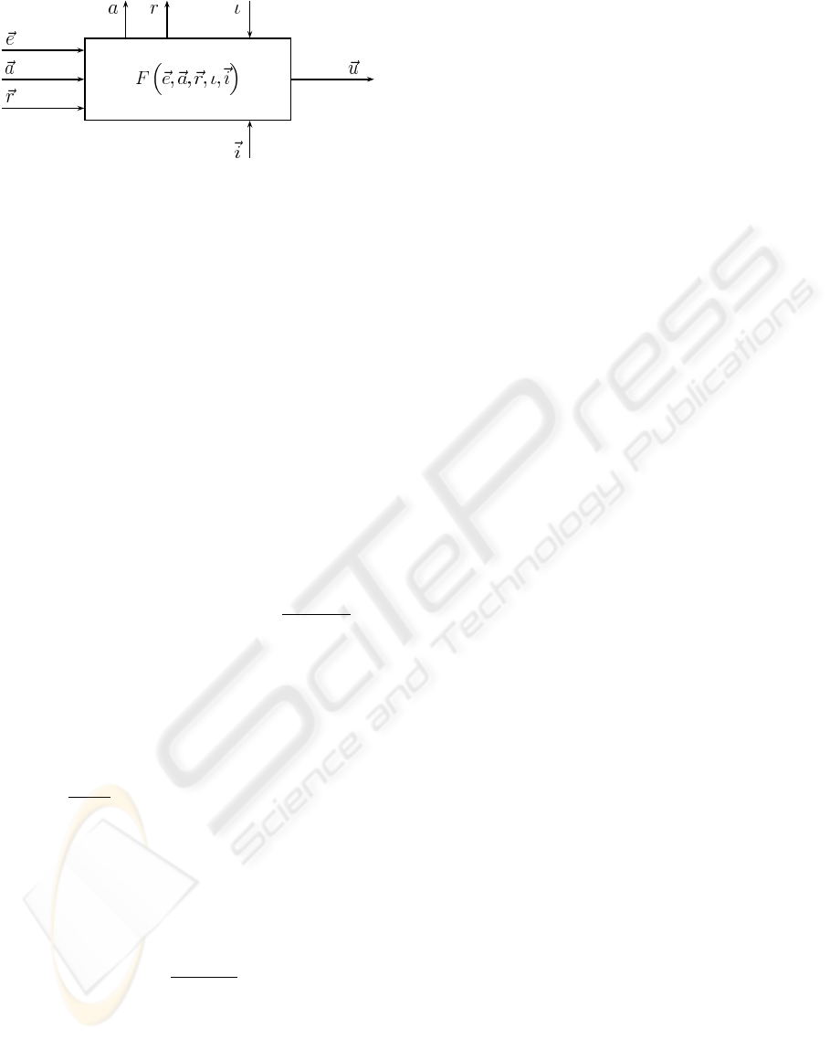
Figure 4: Fusion behaviour module.
activity. The interface of fusion behaviours imple-
ments a refinement of usual behaviours. For each of
the competing behaviours
B
i
the activity (indicated by
~a), target rating (indicated by~r) and output vector~u is
provided. The output vector is fed into the fusion be-
haviour as~e. Additionally there is a fusion of inhibit-
ing behaviours by the inhibition inputs
~
i. The transfer
function then is the fusion function f(~a,~e) which pro-
cesses these input values to a merged output control
vector~u.
The fusion function can have several implementa-
tions, in this work the weighted fusion is used: Here
the control values are weighted with the activity of the
corresponding behaviour, leading to a fusion function
f
weighted
, where
~u = f
weighted
(a
0
,~u
0
,. .. , a
n−1
,~u
n−1
) =
n−1
∑
j=0
a
j
·~u
j
n−1
∑
k=0
a
k
(3)
The activity is set according to the weighted input ac-
tivities, the activation, and the maximally activated in-
hibiting behaviour:
a =
n−1
∑
j=0
a
2
j
n−1
∑
k=0
a
k
· ι· (1− i
m
) where i
m
= max
l
(i
l
)
The target rating of a fusion behaviour indicates its
goal to satisfy highly activated input behaviours and
is calculated as follows:
r =
n−1
∑
j=0
a
j
· r
j
n−1
∑
k=0
a
k
The weighted fusion function provides a subtle
gradation of coordinating behaviour control outputs
regarding their activity.
3.4 Behaviour Network of Ravon
The behaviour network implemented on RAVON is
shown in Fig. 5. Here the flow of control data is
marked as blue drawn through line while data de-
rived from sensors as well as interpreted sensor data
(e.g. the activity output of behaviours used as inhi-
bition input for fusion behaviours) is marked as red
dashed line.
The behaviour network comprises three control
chains affecting desired rotation, sideward motion,
and velocity of the vehicle. The rotational and
the sideward components are influenced by obstacle
avoidance behaviours. For safety reasons the velocity
is adjusted according to obstacle proximity and criti-
cal vehicle inclination. In this behaviour network the
following types of behaviours are used:
• Emergency Stop: Stop due to laser scanner data,
positive or negative obstacles detected by the cam-
era system; independently used for forward and
backward motion.
• Slow Down: Reduce velocity due to obstacle
proximity (laser scanner, positive/negative obsta-
cles); independently used for forward and back-
ward motion.
• Keep Distance Rotational: Turn away from obsta-
cles (laser scanner, positive/negative obstacles);
independently used for both sides of the vehicle.
• Keep Distance Sideward: Accomplish sideward
motion due to obstacles at the side; independently
used for both sides of the vehicle.
• Evasion: Evade obstacles at the front by arbitrat-
ing between the keep distance behaviours.
• Point Access: Accessing a given position.
• Point Access Ranking: Perform ranking manoeu-
vres accounting for kinematic constraints.
• Trace Back: Follow just driven path backwards in
order to escape dead ends.
The advantage of this approach is the emergent
vehicle behaviour leading to unforeseen, but suitable
reaction on several external influences at a time. How-
ever, especially the maintenance of vehicle and person
safety requires methods for guaranteeing fundamental
characteristics of the vehicle motion e.g. in critical sit-
uations. Therefore, it is necessary to formally verify
the behaviour network with respect to a given set of
specifications.
ICINCO 2007 - International Conference on Informatics in Control, Automation and Robotics
160
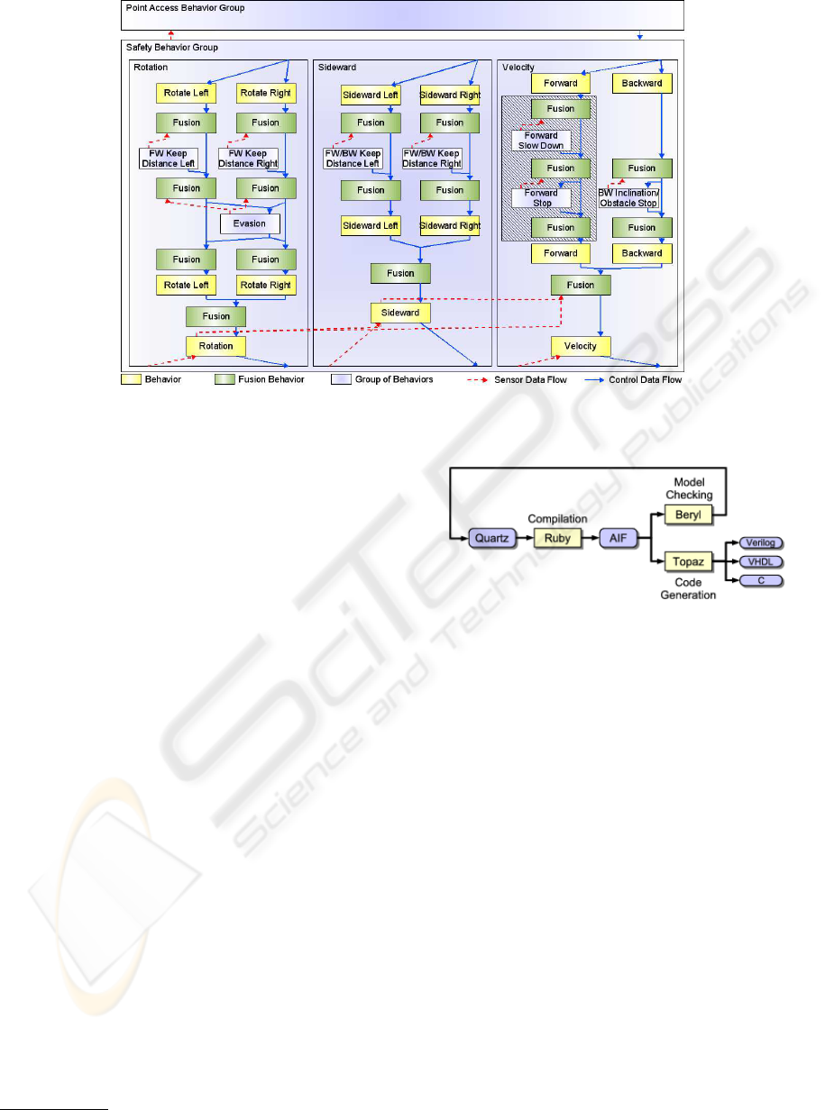
Figure 5: Behaviour network of RAVON.
4 THE AVEREST SYSTEM
In this section, we describe the Averest
1
frame-
work (Schneider and Schuele, 2005; Schneider and
Schuele, 2006) that provides tools for verifying
temporal properties of synchronous programs (Ben-
veniste et al., 2003; Halbwachs, 1993) as well as for
compiling these programs to equivalent hardware and
software systems. In particular, many formal verifi-
cation techniques, including model checking of tem-
poral properties of finite and infinite state systems
are available. In Averest, a system is described us-
ing the Esterel–like synchronous programming lan-
guage Quartz (Schneider, 2001a), and specifications
can be given in temporal logics such as LTL and CTL
(Schneider, 2003). Currently, Averest consists of the
following tools:
• ruby: a compiler for translating Quartz programs
to finite and infinite state transition systems
• beryl: a symbolic model checker for finite and in-
finite state transition systems
• topaz: a code generator to convert transition sys-
tems into hardware and/or software
Figure 6 shows the typical design flow. A given
Quartz program is first translated to a symbolically
represented transition system in Averest’s Interchange
Format AIF that is based on XML. The AIF de-
scription can then be used for verification and code
generation. Moreover, there are interfaces to third–
party tools, e.g. other model checkers such as SMV
1
http://www.averest.org
Figure 6: Averest design flow.
(McMillan, 1992). In the remainder of this section,
we describe some background information on Averest
focusing on the verification of behaviour networks.
The basic paradigm of synchronous languages
(Benveniste et al., 2003; Halbwachs, 1993) is the
distinction between micro and macro steps in a pro-
gram. From a programmer’s point of view, micro
steps do not take time, whereas macro steps take one
unit of time. Hence, consumption of time is explicitly
programmed by partitioning the program into macro
steps. This programming model, referred to as per-
fect synchrony (Benveniste et al., 2003; Halbwachs,
1993), together with a deterministic form of concur-
rency allows the compilation of multi–threaded syn-
chronous programs to deterministic single–threaded
code. A distinct feature of synchronous languages is
their detailed formal semantics that is usually given
by means of transition rules in structural operational
semantics. This makes synchronous languages attrac-
tive for safety–critical applications where formal ver-
ification is mandatory.
After translating a Quartz program to a transi-
tion system, it can be verified using symbolic model
FORMAL VERIFICATION OF SAFETY BEHAVIOURS OF THE OUTDOOR ROBOT RAVON
161
checking techniques. For that purpose, the specifi-
cations are given as a set of temporal logic formulas
that describe the desired properties of the system. The
most frequently used properties are safety and live-
ness properties. Intuitively, a safety property states
that a condition invariantly holds on a given path of
the transition system. Similarly, a liveness property
states that a condition holds at least once on a given
path. As an example for a safety property, the formula
AGϕ states that ϕ holds on all possible computation
paths of the system. An example for a liveness prop-
erty is the formula EFϕ, stating that there exists a path
such that ϕ eventually holds.
A breakthrough in formal verification was
achieved in the early nineties, where it was observed
that finite sets can be efficiently represented by means
of binary decision diagrams (BDDs), a canonical nor-
mal form for propositional logic formulas (Bryant,
1986). The development of BDDs was a cornerstone
for symbolic model checking procedures based on fix-
point computations (Burch et al., 1990) (see textbooks
like (Clarke et al., 1999; Schneider, 2003) for more
details). With sophisticated implementations and re-
finements of symbolic model checking, it has become
possible to verify systems of industrial size, and to de-
tect errors that can hardly be found using simulation
(Clarke and Wing, 1996).
5 FORMAL VERIFICATION OF
THE BEHAVIOUR NETWORK
In case of RAVON, the most important behaviour
network property is the control of the vehicle ve-
locity due to obstacles or critical inclination. The
behaviours affecting the control in this respect are
marked hatched in Fig. 5. In order to formally verify
this part of the behaviour network, the correspond-
ing behaviours have been implemented in the syn-
chronous language Quartz. In this way, the correct-
ness of every single behaviour can be shown by means
of a symbolic model checker. By forming a group of
the mentioned behaviours, it is even possible to verify
specifications concerning the overall behaviour of the
complete velocity control part of the behaviour net-
work. Moreover, the Quartz code can be exported to
C code and can be wrapped into a module that re-
places the original (unverified) code. As the output of
the verified module is directly transferred to the vehi-
cle motion actuators, it can be guaranteed that slowing
down and stopping has the intended effect.
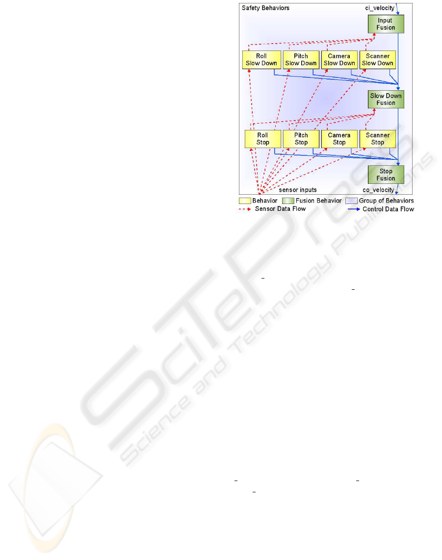
The verified and synthesized parts of RAVON’s
behaviour network are depicted in in Fig. 7. It shows
the following structure: If none of the slow-down and
Figure 7: Structure of the verified part of RAVON’s be-
haviour network.
stop behaviours is active, the velocity given by higher
layers (ci
velocity) is piped through the three fusion
behaviours without change to co
velocity. As soon as
one of the mentioned behaviours becomes active (in
case the inclination rises above a threshold or the ob-
stacle distance becomes too low), the active behaviour
uses its activity to inhibit the fusion behaviour which
is above it. At the same time, it proposes a velocity
of zero to the underlying fusion behaviour. This fu-
sion behaviour calculates a weighted sum (using the
input activities) of the input velocity values. The more
active a behaviour becomes, the less active the fu-
sion behaviour above is. Therefore, the influence of
the slow-down behaviour rises and the velocity output
of the underlying fusion behaviour decreases. This
mechanism is implemented on two layers here.
For this behaviour network, we checked eight
specifications including the ones we list below. In this
context, uppercase words indicate system parameters,
ci
indicates controller inputs,
co
controller outputs,
and
si
sensor inputs. Numbers are marked as un-
signed integers (
0u
).
• The output velocity is never higher than the input
velocity:
A G (co_velocity <= ci_velocity);
• In case of no near obstacle and tolerable inclina-
tion, the output velocity equals the input velocity.
Therefore, the vehicle is not slowed down without
a reason:
A G ((si_camera_distance
>= MAX_VELOCITY_OBSTACLE_DISTANCE)
ICINCO 2007 - International Conference on Informatics in Control, Automation and Robotics
162
& (si_scanner_distance
>= MAX_VELOCITY_OBSTACLE_DISTANCE)
& (si_roll
<= MAX_VELOCITY_INCLINATION)
& (si_pitch
<= MAX_VELOCITY_INCLINATION)
-> co_velocity == ci_velocity);
• If very high inclination or very near obstacles oc-
cur, the output velocity is set to zero, i.e., the ve-
hicle stops:
A G (si_roll >= STOP_INCLINATION
-> co_velocity == 0u);
A G (si_pitch >= STOP_INCLINATION
-> co_velocity == 0u);
A G (si_camera_distance
<= STOP_OBSTACLE_DISTANCE
-> co_velocity == 0u);
A G (si_scanner_distance
<= STOP_OBSTACLE_DISTANCE
-> co_velocity == 0u);
• In case of a rising roll angle, the vehicle slows
down. Similar specifications hold for the pitch an-
gle and for near obstacles:
A G (ci_velocity == MAX_VALUE
& si_camera_distance
> MIN_VELOCITY_OBSTACLE_DISTANCE
& si_scanner_distance
> MIN_VELOCITY_OBSTACLE_DISTANCE
& si_pitch
< MIN_VELOCITY_INCLINATION
& si_roll
> MAX_VELOCITY_INCLINATION
& si_roll
< MIN_VELOCITY_INCLINATION
-> co_velocity < MAX_VALUE
& co_velocity > 0u );
In order to avoid vacuous specifications, formulas of
the type AG(ϕ → ψ) are always complemented with
EFϕ (not shown here). In this way, it is guaranteed
that the antecedent of the implication is not always
false. All of our specifications can be expressed in
the temporal logic CTL. Hence, we can use state-
of-the-art model checking techniques to verify these
properties. Using global model checking, the model
checkers perform a complete traversal of the reach-
able states and thereby check whether the given speci-
fications hold. Using local model checking, the model
checkers perform some sort of an induction proof to
avoid a complete state space traversal.
BDD-based symbolic model checkers do usually
not support floating point numbers. Therefore, inte-
gers with a given bitwidth are used for the implemen-
tation in Quartz instead of floating point numbers. In
order to integrate the verified module in the control
system, a conversion from floating point to fixpoint
numbers is performed for control and sensor values.
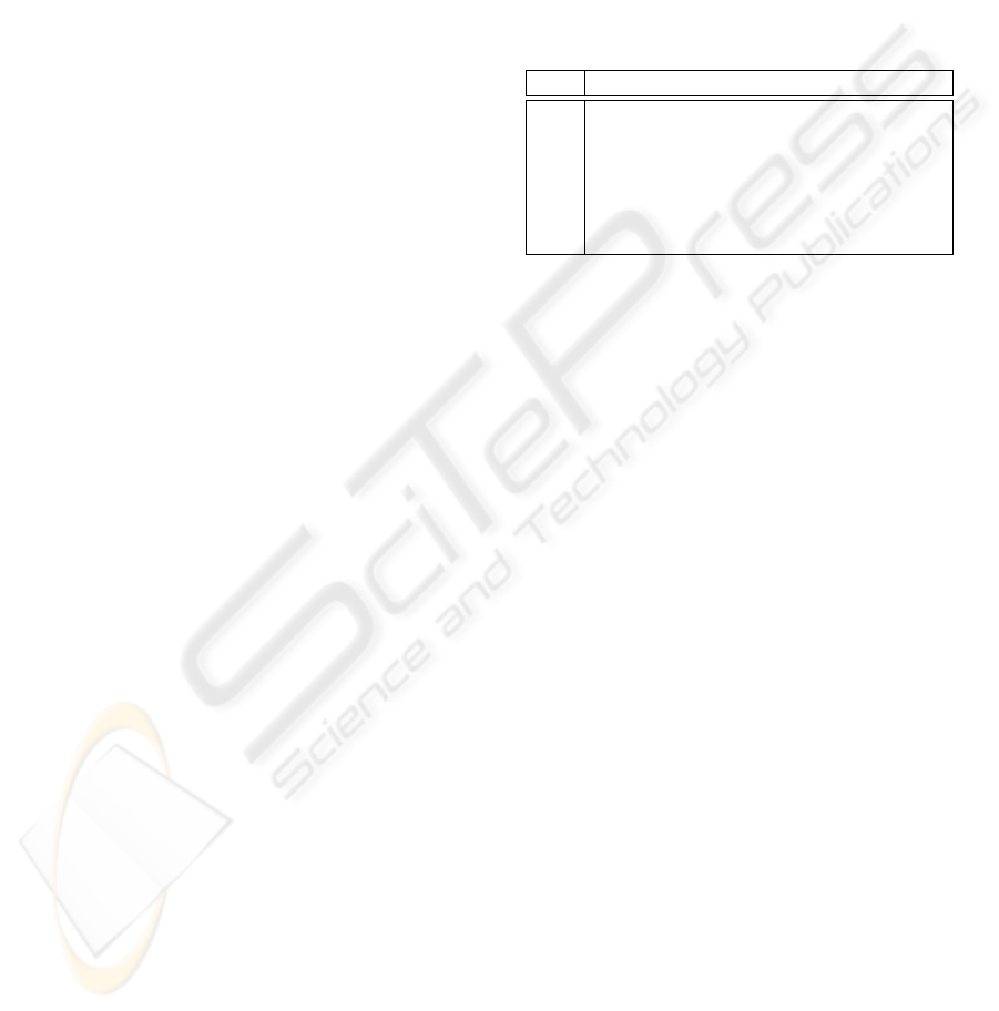
In our case study, global model checking was able
to check the specifications up to a sufficiently large
bitwidth. We used CadenceSMV as backend of Aver-
est. In the following table, we list experimental re-
sults for some bitwidths. For each bitwidth, we list
the number of reachable states, the runtime that was
necessary to verify the system, and the number of re-
quired BDD nodes for the entire verification of the
eight specifications. All experiments were performed
on a PentiumIV with 512 MByte main memory.
Table 1: Experimental results of the verification process.
bits states runtime (s) BDD nodes
3 1024 0.95 453
4 8192 1.59 10012
5 65536 2.54 10063
6 524288 3.87 10521
7 4194204 5.54 15399
8 33554432 8.85 49500
In the process of implementing the behaviour net-
work, the question arose if the fusion behaviours
could implement a maximum fusion function (i.e. the
most active behaviour has full influence) instead of
the weighted fusion function. By means of formal
verification, it was possible to show that in this case
not all specifications were valid. Depending on the
implementation, there was either no slowing down of
the vehicle (but only abrupt stopping) or it was possi-
ble that the velocity output was higher than the veloc-
ity input. Experimental changes concerning the struc-
ture and implementation of the behaviour network
can therefore be performed with immediate feedback
about the correct properties stated in the specifica-
tions.
6 CONCLUSIONS AND FUTURE
WORK
We presented an approach to the formal verification of
a behaviour-based control network. Without the need
of testing, it is guaranteed that the specified proper-
ties are valid for all possible input traces. Of course,
it is necessary to verify more parts of the system or
even the complete behaviour-based network. Due to
the enormous number of states, this inevitably leads to
the need of improving the model checking approach.
Therefore, methods like modular model checking and
abstraction will have to be analysed in this respect.
The uniformity of the behaviours is seen to be an ad-
vantage in this context that can be exploited by tai-
lored verification and abstraction techniques.
FORMAL VERIFICATION OF SAFETY BEHAVIOURS OF THE OUTDOOR ROBOT RAVON
163

ACKNOWLEDGEMENTS
The research work presented in this paper is funded
by the German Federal State of Rhineland-Palatinate
within the excellence cluster ”Dependable Adaptive
Systems and Mathematical Modeling”.
REFERENCES
Benveniste, A., Caspi, P., Edwards, S., Halbwachs, N., Le
Guernic, P., and de Simone, R. (2003). The syn-
chronous languages twelve years later. Proceedings
of the IEEE, 91(1):64–83.
Berry, G. (1998). The foundations of Esterel. In Plotkin, G.,
Stirling, C., and Tofte, M., editors, Proof, Language
and Interaction: Essays in Honour of Robin Milner.
MIT.
Bryant, R. (1986). Graph-based algorithms for Boolean
function manipulation. IEEE Transactions on Com-
puters, C-35(8):677–691.
Burch, J., Clarke, E., McMillan, K., Dill, D., and Hwang,
L. (1990). Symbolic model checking: 10
20
states and
beyond. In Symposium on Logic in Computer Science
(LICS), pages 1–33, Washington, D.C. IEEE Com-
puter Society.
Clarke, E., Grumberg, O., and Peled, D. (1999). Model
Checking. MIT, London, England.
Clarke, E. and Wing, J. (1996). Formal methods: State
of the art and future directions. Technical Report
CMU-CS-96-178, Carnegie Mellon University.
ftp://reports.adm.cs.cmu.edu/usr/anon/1996/CMU-
CS-96-178.ps.
Diethers, K., Firley, T., Krger, T., and Thomas, U. (2003).
A new framework for task oriented sensor based robot
programming and verification. In International Con-
ference on Advanced Robotics (ICAR), pages 1208–
1214, Coimbra,Portugal. IEEE Computer Society.
Halbwachs, N. (1993). Synchronous programming of reac-
tive systems. Kluwer.
Kim, M. and Kang, K. (2005). Formal construction and
verification of home service robots: A case study. In
Peled, D. and Tsay, Y.-K., editors, International Sym-
posium on Automated Technology for Verification and
Analysis (ATVA), volume 3707 of LNCS, pages 429–
443, Taipei, Taiwan. Springer.
McMillan, K. (1992). The SMV system, symbolic model
checking - an approach. Technical Report CMU-CS-
92-131, Carnegie Mellon University.
Sch
¨
afer, H. and Berns, K. (2006). Ravon - an autonomous
vehicle for risky intervention and surveillance. In In-
ternational Workshop on Robotics for risky interven-
tion and environmental surveillance - RISE.
Schmitz, N., Proetzsch, M., and Berns, K. (2006). Pose esti-
mation in rough terrain for the outdoor vehicle ravon.
In 37th International Symposium on Robotics (ISR).
Schneider, K. (2001a). Embedding imperative synchronous
languages in interactive theorem provers. In Confer-
ence on Application of Concurrency to System Design
(ACSD), pages 143–156, Newcastle upon Tyne, UK.
IEEE Computer Society.
Schneider, K. (2001b). Exploiting Hierarchies in Temporal
Logics, Finite Automata, Arithmetics, and µ-Calculus
for Efficiently Verifying Reactive Systems. Habilitation
Thesis. University of Karlsruhe.
Schneider, K. (2003). Verification of Reactive Systems –
Formal Methods and Algorithms. Texts in Theoretical
Computer Science (EATCS Series). Springer.
Schneider, K. (2006). The synchronous programming lan-
guage Quartz. Internal Report (to appear), Department
of Computer Science, University of Kaiserslautern.
Schneider, K. and Schuele, T. (2005). Averest: Specifica-
tion, verification, and implementation of reactive sys-
tems. In Conference on Application of Concurrency
to System Design (ACSD), St. Malo, France. partici-
pant’s proceedings.
Schneider, K. and Schuele, T. (2006). A framework for
verifying and implementing embedded systems. In
Straube, B. and Freibothe, M., editors, Methoden und
Beschreibungssprachen zur Modellierung und Veri-
fikation von Schaltungen und Systemen, pages 242–
247, Dresden, Germany. GI/ITG/GMM, Fraunhofer
Institut fr Integrierte Schaltungen, ISBN 3-9810287-
1-6.
Schuele, T. and Schneider, K. (2006). Bounded model
checking for infinite state systems. Formal Methods
in System Design (FMSD). DOI 10.1007/s10703-006-
0019-9.
Sharygina, N., Browne, J., Xie, F., Kurshan, R., and Levin,
V. (2004). Lessons learned from model checking a
NASA robot controller. Formal Methods in System
Design (FMSD), 25(2-3):241–270.
Sowmya, A., So, D., and Tang, W. (2002). Design of a mo-
bile robot controller using Esterel tools. Electronic
Notes in Theoretical Computer Science (ENTCS),
65(5). Workshop on Synchronous Languages, Appli-
cations, and Programming (SLAP).
ICINCO 2007 - International Conference on Informatics in Control, Automation and Robotics
164
