
A NEURAL-CONTROL SYSTEM FOR A HUMANOID ARTIFICIAL
ARM
Michele Folgheraiter, Giuseppina Gini and Massimo Cavallari
Department of Electronics and Information, Politecnico di Milano, Piazza L. da Vinci 32, Milano, I-20133, Italy
Keywords:
Biorobotics, Artificial Arm, Neural Controller, Humanoids Robotics.
Abstract:
In this paper we illustrate the architecture and the main features of a bio-inspired control system employed
to govern an anthropomorphic artificial Arm. The manipulation system we developed was designed starting
from a deeply study of the human limb from the anatomical, physiological and neurological point of view. In
accordance with the general viewofthe Biorobotics field we try to replicate the structure and the functionalities
of the natural limb. Thanks to this biomimetic approach we obtained a system that can perform movements
similar to those of the natural limb.
The control system is organized in a hierarchical way. The low level controller emulates the neural circuits
located in the human spinal cord and is charged to reproduce the reflexes behaviors and to control the arm
stiffness. The high level control system generates the arm trajectory performing the inverse kinematics and
furnishing the instantaneous muscles reference position. In particular we implemented the Inverse kinematic
using a gradient based algorithm; at each step the actuators movements are arranged in order to decrease the
distance between the wrist and the target position.
Simulation and experimental results shows the ability of the control system in governing the arm to follow a
predefined trajectory and to perform human like reflexes behaviors.
1 INTRODUCTION
Robotics since from the beginning was involved in
replicating the human manipulation capabilities. One
of the first manipulators, designed for research pur-
poses, was the Stanford Arm (Stanford Artificial In-
telligence Laboratory). This robot was furnished of 6
DOFs (Degree Of Freedom), five revolute joints and
one prismatic. Even if the mechanical architecture
was thought with the aim to emulate the human move-
ments we can not consider it as a real anthropomor-
phic system.
In sixties General Motor (the first to employ a
Manipulator in an industrial process) financed a re-
search program at MIT to developed another well
know robotics arm: the PUMA (Programmable Uni-
versal Manipulator for assembly).
We can classify this manipulator as anthropomorphic,
indeed it is possible to compare it to a human arm. At
first we can divide the mechanical structure in three
principal blocks: the shoulder with two DOF, the el-
bow with 1 DOF and the wrist with another three
DOF. The Puma has a dexterity that is quite near to
that of a human arm, even though the human shoulder
has more than two DOF. The analogy between the hu-
man arm and the PUMA manipulator is true only from
a kinematic point of view, because the two systems
have completely different performances. We can as-
sert that this robot is more precise than a human arm,
nevertheless the natural arm is structurally conformed
to perform tasks that require compliant features, like
clean an irregular surface or catch a ball.
A fine regulation of the joint stiffness is therefore
very important also in a Humanoid Robot, indeed if
we want that the robot will be able to perform a task
in collaboration with a human being we have the ne-
cessity to change the joints stiffness in concomitance
with the robot movements. In industrial manipulators
it is possible to set the end-effector compliance using
the information coming from a three axis force sensor
119
Folgheraiter M., Gini G. and Cavallari M. (2007).
A NEURAL-CONTROL SYSTEM FOR A HUMANOID ARTIFICIAL ARM.
In Proceedings of the Fourth International Conference on Informatics in Control, Automation and Robotics, pages 119-126
Copyright
c
SciTePress

installed on the wrist, nevertheless this is quite simi-
lar to a virtual compliance control. In fact, the motors
that equip the manipulator do not present an intrinsi-
cal compliance, normally if the power is switch off the
robot assumes its maximum rigidity. This behavior is
not acceptable for a robot that is thought to operate in
strict contact with a human being.
With this work we want to propose a different
methodology in developing such a systems, not only
we tried to emulate the human arm morphology, but
we implemented also a neural controller that repli-
cates the functionalities of primary motor circuits lo-
cated in the human spinal cord. We are convinced that
combining classical control methodologies with bio-
inspired one may brings a new class of machines that
will perform better.
There are many projects that attempted to design
an arm with human like features and capabilities. At
the Center for Intelligent Systems (Vanderbilt Univer-
sity) Prof. Kawamura and its group are working on
the ISAC humanoid robot. This robot consists of a
human-like trunk equipped with two six-DOF arms
moved by McKibben artificial muscles (Kawamura
et al., 2000). Each joint is actuated by two antago-
nistic actuators that are controlled by a system able to
emulate the electromyogram patterns (EMG) of a hu-
man muscle. The arm, during a fast reaching move-
ment, can avoid an obstacle performing a reflex be-
havior (Gamal et al., 1992), furthermore the phasic
pattern is autonomously adjusted when a reach trajec-
tory doesn’t closely match a desired response. The
main advantage of this bio-mimetic control architec-
ture is the possibility to reduce the joint stiffness dur-
ing a movement execution.
Another project in the same direction is that one at
the Biorobotics Laboratory in Washington University.
Here Prof. Hannaford and his team have worked in-
tensely on the emulation of the human arm (Han-
naford and Chou, 1997) (Hannaford et al., 1995).
The goal of this research is to transfer knowledge
from human neuro-musculo-skeletal motion control
to robotics in order to design an ”anthroform” robotic
arm system.
Following the bio-mimetic approach they devel-
oped and tested new kind of actuators (Klute and Han-
naford, 2000) and sensors (Hannaford et al., 2001)
(Jaax, 2001), whose purpose is to replicate a mam-
malian muscle spindle cell, that measures the contrac-
tion and the muscle velocity.
Another very interesting arm project is that one
developed by Department of Precision Machinery
Engineering in University of Tokyo. The sys-
tem(Toshiki Niino and Higuchi, 1994) is equipped
with a new types of compact, high-power, electrostat-
ically driven actuators.
The actuators have 40 or 50 pairs of sheets inter-
leaved together and enclosed in ready-to-use pack-
ages filled with a dielectric liquid. An electrostatic
artificial muscle consists of two groups of sheets
stacked and interleaved together. Sliding forces are
generated on the surface of each film and are com-
bined into a net force at the bundled edges of the
sheets.
A first type of pulse-drive induction artificial mus-
cle, which utilizes induced charges on highly resistive
films, generated 8N propulsive force and 0.5W me-
chanical power with 110g its own mass. At the Dept.
of Mechanical Engineering (Vrije Universiteit Brus-
sel) Prof. Frank Daerden et al designed a new type
of Pneumatic Artificial Muscle (PMA), namely the
Pleated Pneumatic Artificial Muscle (PPAM) (Daer-
den and Lefeber, 2001). It was developed as an im-
provement with regard to existing types of PAM, e.g.
the McKibben muscle (Klute and Hannaford, 2000).
Its principal characteristic is its pleated mem-
brane. It can inflate without material stretching and
friction and has practically no stress in the direction
perpendicular to its axis of symmetry. Besides these
it is extremely strong and yet very lightweight and it
has a large stroke compared to other designs.
2 THE ARM ARCHITECTURE
AND FEATURES
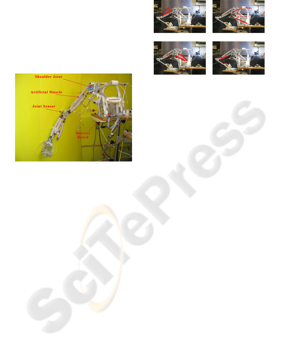
In 2003 we developed a first prototype of artificial
Arm (MaximumOne Figure 1) with the main aim to
experience the actuation architecture and the control
strategies we theorized.
From the kinematic point of view, if we exclude
the hand, the system presents overall four degrees of
freedom. Three are located in the shoulder that re-
sembles a spherical joint, and one in the elbow that is
a normal revolution joint.
Each joint is actuated by tendons connected with
McKibben artificial muscles. In order to detect the
arm posture and allow to close the control loop, each
actuator is equipped with a position and force sensor.
These devices were developed specifically for this ap-
plication, this because there are not commercial sys-
tem that meet our needs. Furthermore the elbow joint
is furnished of an angular sensor (Figure 1) that mea-
sures the joint position.
The signals coming from the sensors are condi-
tioned and gathered by dedicated boards that per-
form an analog multiplexing and send the informa-
tion to a Target-PC equipped with a real-time ker-
nel. The control system, implemented via software
on a Host-PC, receives and elaborates these informa-
tion via RS-232 serial connection and send back its
output, through the Target-PC, to the electro-valves
module that has the main purpose to set the actuators
pressures. This module is equipped with 14 micro
solenoid-valves that can operate at a maximum fre-
quency of 20Hz. Using a PWM (Pulse Wide Modula-
tion) modulation it is possible to regulate the air flow
that feeds the single actuator and therefore its force
and position.
Figure 1: MaximumOne,the Arm Prototype of the Artifi-
cial Intelligence and Robotics Laboratory, Politecnico di
Milano.
As it is possible to see from the picture (Figure 1),
the arm we developed has an anthropomorphic shape.
This because during the design, we have tried to re-
produce the human arm dimensions and proportions,
the articulation mobilities, the muscle structure, and
the same sensorial capabilities.
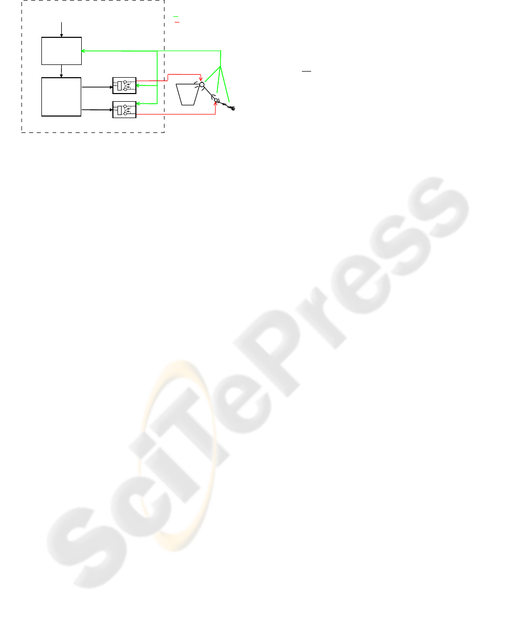
2.1 The Actuation System
In order to actuate the arm we used seven artificial
muscles (Figure 2): five are dedicated to the shoulder
joint and two to actuate the elbow. This permits us
to obtain the typical postures and movements of the
natural limb. The five shoulder actuators emulate the
mechanical functionalities of: pectoralis major, dorsal
major, deltoid, supraspinatus and subscapularis mus-
cles. The two elbow actuators emulate the functions
of biceps and triceps muscles.
If we compare the the human arm musculature
with the actuation system of our prototype we can find
out same differences; for example the actuators that
represent the biceps and triceps muscles are mono-
link in the sense that they are dedicated only for the
elbow actuation, instead in the human limb they in-
terest at the same time the shoulder and elbow artic-
ulations. Furthermore shoulder actuators are placed
a. b.
c. d.
Figure 2: (a) The Deltoid Actuator lifts the shoulder. (b)The
Pectoral and Dorsal Actuators allow the adduction and ab-
duction movements. (C)The Supraspinatus and Subscapu-
laris Actuators allow the shoulder rotation. (d) The Biceps
and Triceps Actuators allow the elbow flexion and exten-
sion.
in a manner to maximize the space available for their
movement. Indeed, because of McKibben actuators
can contract only the 20% of their maximum length,
depending on the tendon excursion we need to realize,
their minimum length is fixed.
3 CONFIGURATION OF THE
CONTROL SYSTEM
The control system of the arm is organized in a
modular and hierarchical fashion. At the bottom
level (Figure 3) there are the artificial reflex mod-
ules(Michele Folgheraiter, 2004) that govern the ac-
tuator’s contraction and force. These modules receive
inputs from the joint path generator, which in turn is
fed by the Inverse Kinematic module that computes
the target actuators lengths. The inputs of the en-
tire control system are: the final hand position in the
cartesian space, and the P signal that scales the level
of artificial muscles co-activation (simultaneously ac-
tivation of the muscle that govern the same joint ).
From a hierarchical point of view, we can distin-
guish three main levels:
• High level controller: composed by the Inverse
Kinematic modules
• Medium level controller: composed by the path
generator module
• Low level controller: composed of the reflex
modules that control the artificial muscles activ-
ities
Shoulder
Elbow
Hand
Sensory Information
Control Commands
Trajectory Generator
and
Inverse Kinematic
Module
Shoulder Reflex
Module
Elbow Reflex
Module
Path Generator
Module
Control Architecture
M1
M2
M1
M2
Wrist Trajectory
and
joints stifness
L(t),V(t)
E(t)
L
Figure 3: Control System Architecture.
The signals transmitted from one module to an-
other are expressed in a vectorial form, where each
vector component corresponds to one of the seven
artificial muscles that compose the actuation system.
Therefore L
T
represents the target lengths vector for
the actuators, V
T
represents the target velocity vec-
tor, E
L
represents the length vector error, and P is the
stiffness command vector. At the level of each single
module these signals are decomposed in their compo-
nents and sent to the appropriate submodules.
4 ARTIFICIAL NEURAL
CIRCUITS TO IMPLEMENT
THE REFLEXES BEHAVIORS
Reflex behaviors are accomplished by two modules
that implement a simplified model of the natural cir-
cuits present in the human spinal cord. One module is
dedicated to the control of the artificial muscles activ-
ities that govern the shoulder joint, the other takes un-
der control muscles that actuate the elbow joint. Since
the artificial muscle is constituted by only one func-
tional fiber the biological organization of the natural
muscle in motor units is neglected in our model. The
artificial muscle activity is therefore regulated by only
one motoneuron. The same consideration can be done
also for the sensorial system in the muscle, that in this
case is constituted by only one artificial spindle organ
and only one artificial Golgi tendon organ.
The most important cells of the neural circuit are
the motoneurons whose outputs set the actuators pres-
sures. With respect to other models in literature (Ster-
ratt, 2001),(Kuntimad and Ranganath, 1999),(Fol-
gheraiter and Gini, 2001) or to hardware solutions
(Omura, 1999) we decided to neglect the spike be-
havior of these cells, instead we concentrated our at-
tention on modelling its membrane potential.
Each motoneuron receives its inputs from almost
all the cells that compose the circuit. In equation 1 M
i
represents the potential (membrane potential) of the
motoneuron i.
d
dt
M
i
= (1−M
i
)(exc
i
) − M
i
(inh
i
) (1)
where the terms exc
i
and inh
i
are the excitatory
and inhibitory inputs for the motoneuron.
The neuron output is represented by equation 2
Mo
i
= Th(M
i
) (2)
where the threshold function is defined by equa-
tions 3 :
Th(x) =
x if 0 ≤ x ≤ 1
0 if x ≤ 0
1 if x ≥ 1
(3)
For more details about this model see (blind).
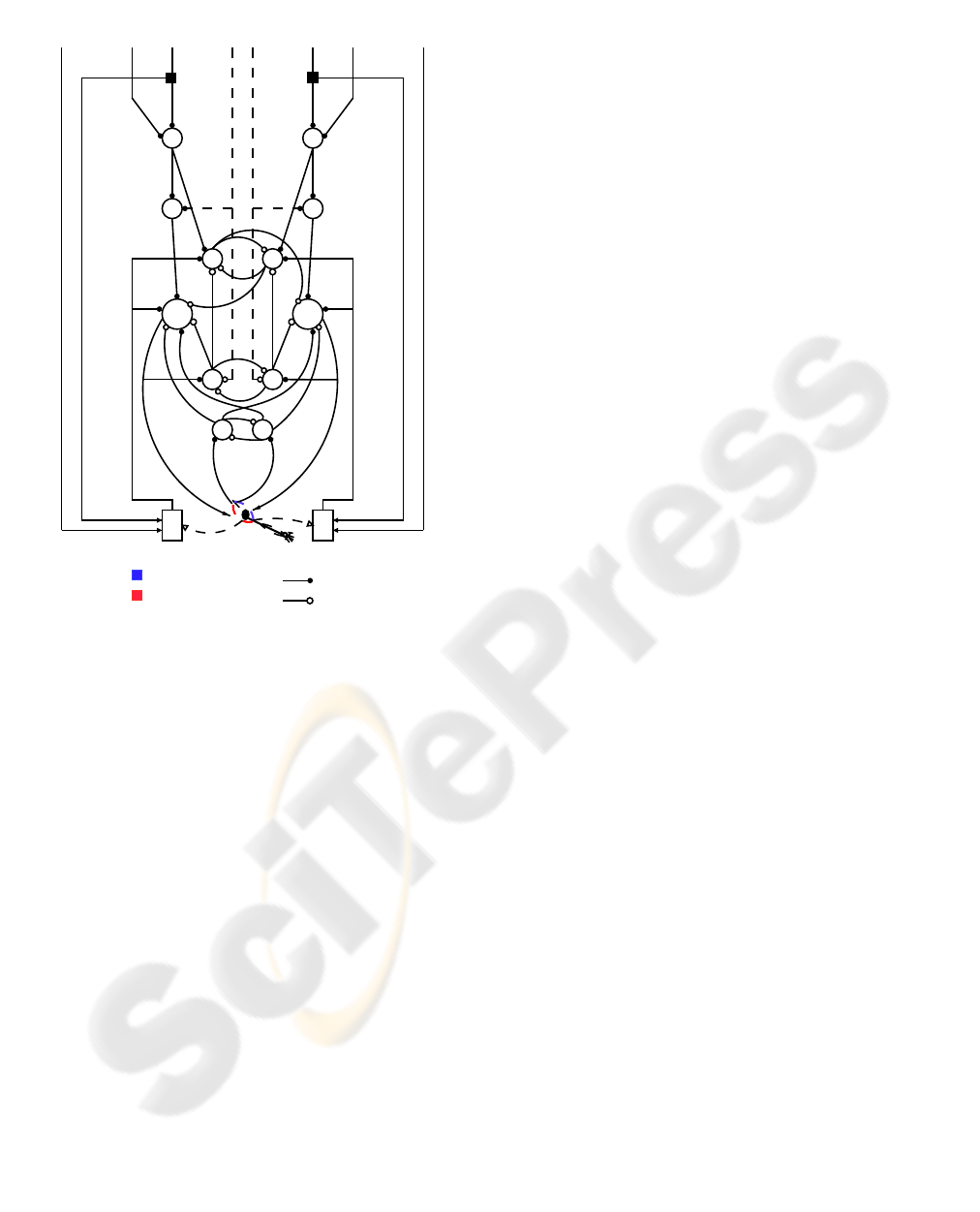
4.1 Elbow Neural Circuit
The reflex module that governs the elbow muscle is
represented in figure 4. It implements an opponent
force controller whose purposes are to provide inputs
for the path generator module, measure movements
error and return error signals when the execution is
different from the desired movement.
In figure 4 M
6
and M
7
are the motoneurons that con-
trol the contraction rate and force of the triceps and
biceps actuators respectively. I
a
6 and I
a
7 are the in-
terneurons that receive the error signals from the ar-
tificial spindles and project, with inhibitory synapses,
to the motoneurons of the antagonist muscles M
7
and
M
6
respectively. R
6
and R
7
represent the Renshaw
cells that receive the error signals from spindles and
inhibit the corresponding motoneuron and I
a
cell, they
are important to reduce oscillations of the joint around
the target angular position. I
b
6 and I
b
7 are interneu-
rons that receive the signals coming from the artifi-
cial Golgi tendon organs (that in this system are rep-
resented by a normalized force measurements). I
ns
6
and I
ns
7 are the interneurons that integrate informa-
tion of stiffness and target length commands.
Finally M
s
6 and M
s
7 represent the artificial muscle
spindle receptors. As inputs they receive the muscle
velocity command, the muscle target length command
and the actual muscle length and in turn excite the cor-
responding motoneuron and I
a
interneurons.
In this work we do not consider the other inputs
(show in the neural circuit schema) for more details
see (Folgheraiter, 2003).
Elbow Joint
Μ6
Μ7
R6
R7
Ia6
Ia7
Ib6
Ib7
Inc6
Inc7
Ins6
Ins7
Ms6
Ms7
Lt6
Lt7
P6
P7
Cs6
Cs7
Vt6
Vt7
Biceps Actuator
Triceps Actuator
Excitatory
Inhibitory
Figure 4: Architecture of the Elbow Reflex Module.
5 TRAJECTORY GENERATION:
DIRECT AND INVERSE
KINEMATIC
In order to test the efficacy of the control system we
developed two kind of arm models:
• The Kinematic Model: it is used in the inverse
kinematic algorithm to calculate the distance be-
tween the target position and the actual position
for the wrist.
• The Dynamic Model: it represents a realistic
model of the arm and takes into account the dy-
namic features of the actuators and of the arm
links.
In this paper we will briefly describe only the Di-
rect Kinematic model, because of it is required to de-
velops the Arm Inverse Kinematic algorithm.
6 DIRECT KINEMATICS
Find the Direct Kinematics of the arm means to find
the function that relates the actuator lengths vector
with the wrist position. In this case the orientation is
not considered because, if we do not take into account
the hand, the kinematic chain, with only four DOF
(three in the shoulder and one in the elbow), does not
allows to set arbitrarily both the position and orien-
tation of the wrist. It is possible to find the Direct
Kinematic of the arm solving a system of equations,
where each one imposes a constraint on the arm posi-
tion. As an example, if we consider the pectoral and
dorsal actuators we can obtains equation 4.
(
(x− Opc
x
)
2
+ (y− Opc
y
)
2
+ (z− Opc
z
)
2
− Lpc
2
= 0
(x− Odo
x
)
2
+ (y− Odo
y
)
2
+ (z− Odo
z
)
2
− Ldo
2
= 0
(x− S
x
)
2
+ (y− S
y
)
2
+ (z− S
z
)
2
− (kS− Opck)
2
= 0
(4)
In equation (Eq. 4 ) (x, y, z) is the position where
the two actuators are connected to the upper-arm,
Opc and Odo represent the origins of the pectoralis
and dorsal respectively, Lpc and Ldo are the actuator
lengths, and S is the shoulder position. All the quan-
tities are referred to the Arm reference system. The
first two equations impose that the distance between
the two extremities of the artificial muscle are equal
to the required distance, instead the third equation im-
poses the condition that at the end of the movement
the position of the attachment of the artificial mus-
cles compared to the bone doesn’t result modified.
As it is possible to see equation 4 has two solutions
and should be recalculated every time the position of
the upper arm changes, indeed it depends on (x, y, z) a
point located on the first robot link.
7 INVERSE KINEMATICS
Inverse Kinematics allows the calculation of the mus-
cles lengths vectors when a target position in the robot
workspace is assigned.
The algorithm we implemented for the Inverse
Kinematics is based on the gradient descent method,
this in order to calculate the minimum of the distance
function between the current and the target wrist po-
sition. It approaches a local minimum by taking steps
that are proportional to the negative of the gradient.
We can codify the algorithm using the pseudo-code of
figure 5.
Where ε
max
is the maximum error allowed in
reaching the target position, and subsets Sub(i) rep-
resents a couple of actuators chosen with a specific
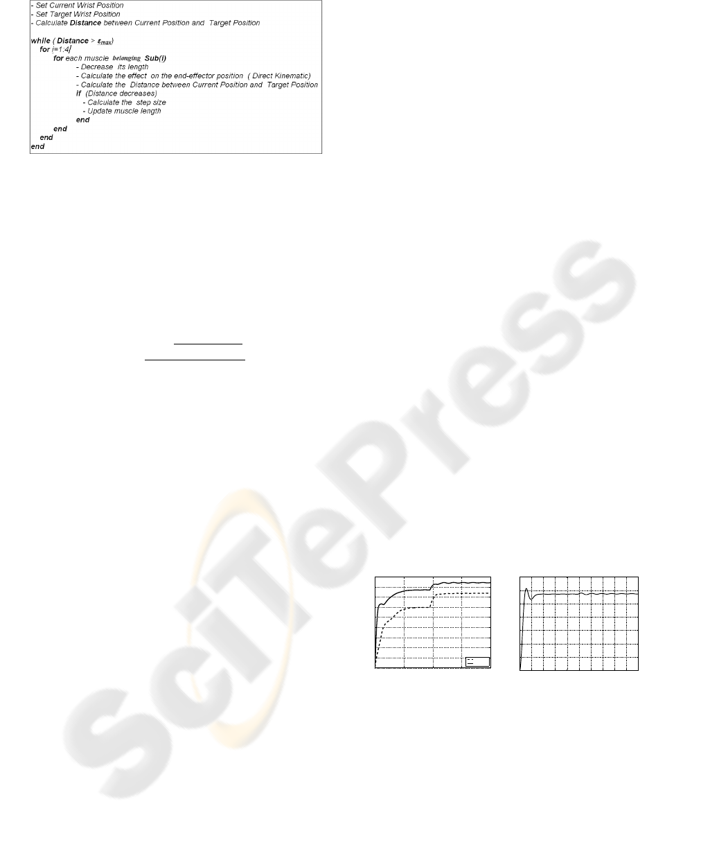
Figure 5: The Algorithm that implement the Arm Inverse
Kinematics. .
logic from the set of all arm actuators.
As it is possible to see the actuator length is de-
creased of a value D specified by equation 5 only if
its decreasing allows to approach the target position,
if not its antagonist actuator is considered at the next
step.
D = −
1− e
−(TargetP−WrisP)
K
1
K
2
(5)
As it is possible to see from equation 5 depending
from the two constant K
1
and K
2
the muscle length
variation decreases according to the decreasing of the
distance between the wrist position (WristP) and the
target position (TargetP).
At each cycle the Direct Kinematic should be cal-
culated and this requires a certain amount of time, in
simulation this does not represent a problem, but may
be critical during the normal arm operation. Never-
theless we can avoid to calculate the direct kinemat-
ics installing on the robot a vision system that can ap-
proximate the distance between the wrist and the tar-
get position. This strategy is very similar to that one
performed by humans when it is required to perform
a motor path in order to reach a target object. At least
during the learning phase, humans being take advan-
tage of the visual feedback to estimate the distance
between the object and the hand.
8 STIFFNESS CONTROL AND
TRAJECTORY FOLLOWING
Here we report the results of some simulations con-
ducted on the robot models. The dynamic model was
developed using the tool SimMechanics in Simulink
environment, we chose an integration step of 1ms in
order to comply with the arm dynamic. At first we
tested the ability of the neural circuit in regulating the
elbow stiffness, in this case a noise force was applied
on the wrist. In the second part of our experiments
we tested the performance of the controller in follow-
ing an assigned trajectory, changing the precision we
show that the algorithm time complexity will decrease
exponentially.
8.1 Joint Stiffness Regulation
The control of the joint’s stiffness is very important
during the execution of a certain task with the robot’s
arm. This is true for industrial robots, but is partic-
ulary important for humanoid robots. Usually indus-
trial manipulators operate in a protected environment
where humans have a restricted access, in order to
guarantee a safe operation for the robot and for the
human. It is difficult to control the joint stiffness for
an industrial manipulator and even if this is possible
the inertia force that acts during the movement can be
lethal for a human being hit by the robot. Humanoid
robots are expected to operate and collaborate with
humans, during a task execution, therefore the robot
must not be dangerous; Humans usually can reduce
or increase the joint stiffness when they are perform-
ing a certain task. For example catching a heavy ob-
ject that is moving fast requires a stiffness increase
of the lower and upper body articulations, while mak-
ing a caress to someone requires a low stiffness for
the arm’s articulations. The articulation’s stiffness, in
turn, is regulated by the muscle cocontraction.
In the reflex modules the stiffness is regulated by the
P
i
signals that excite the Ins interneurons. In order
to demonstrate such a capability in the reflex module
I increased the P
i
signals for the elbow actuators to
the maximum value possible, 1. Picture 6a shows the
forces increasing due to the P command.
0 5 10 15 20
0
10
20
30
40
50
60
70
80
90
Time [s]
Force [N]
Triceps
Biceps
0 2 4 6 8 10 12 14 16 18 20
0
0.2
0.4
0.6
0.8
1
1.2
1.4
Time [s]
Elbow Angular Position [rad]
a. b.
Figure 6: (a) Biceps and Triceps forces during the applica-
tion of a dangerous force to the hand. (b) Elbow angular
position during the increasing of the joint’s stiffness.
The forces in the biceps and triceps actuators in-
crease at the same time, in order to avoid the joint
movement. We can observe also that the triceps in-
creases its force more than the biceps; the important
thing is that the total momentum exercised on the el-
bow joint is equal to zero in order to guarantee its
position (Figure 6b). As it is possible to note, the
elbow position does not change when its stiffness is
increased. We can also observe a collateral effect due
to the stiffness increasing: for a certain period there
are some little oscillations in the elbow joint. Sur-
prisingly this phenomena is present also in humans.
When the muscles are very highly co-contracted, a
tremor will occur in the arm.
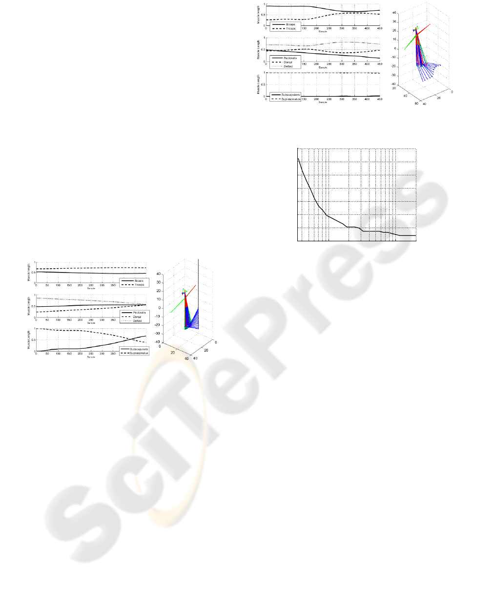
8.2 Trajectory Following
In the first simulation (Figure 7) the arm follows a
straight trajectory from the position (0.46,-14) to the
position (0.46,9), all the quantities are expressed rela-
tively to the robot workspace. In this case we impose
a maximum deviation from the reference trajectory of
6mm, the average error is 5mm. We can increase the
precision, but this will also increase exponentially the
computational time require to calculate the trajectory.
Figure 7: Following a straight trajectory.
In figure 7 are showed also the normalized val-
ues for the actuators lengths, as it is possible to note
the biceps and triceps actuators lengths do not change
considerably. There is instead a big upper arm ro-
tation (relative to an axis which direction is equal to
the first link direction), due to a big variation of the
supraspinatus and subscapularis actuators lengths.
In the second simulation (8) we give as reference a
more complex trajectory (useful for example to avoid
an obstacle in the workspace), also in this case the
trajectory is well followed by the wrist.
Finally figure 9 shows the trend for the compu-
tational time complexity relative to the precision in
reaching the target position. As it is possible to see
the trend is exponential, this means that the chose of
the robot precision is a critical factor for the control
system.
.
Figure 8: Following a complex trajectory.
10
−1
10
0
0
100
200
300
400
500
600
700
Precsion [cm]
Number of Direct Kinematic call
Figure 9: Trend for the time complexity.
9 CONCLUSION AND FUTURE
DEVELOPMENTS
In this paper we describe the architecture and the
main features of an anthropomorphic artificial arm in-
tended for applications in the field of the Humanoid
Robotics. In particular we analyzed its actuation sys-
tem, that emulates the arrangement of the human mus-
culature, and its control system that is organized in a
modular and hierarchical way. The high level con-
troller is charged to generate the arm trajectory and to
perform the inverse kinematic, the low level controller
sets the muscles lengths and the joints stiffness. In or-
der to perform the inverse kinematics we used the gra-
dient descent method, this to calculate the minimum
of the distance function between the current and the
target wrist position. Results show that the arm can
perform different kind of trajectories allowing also
to regulate, during the movement execution, the joint
stiffness. This is very important especially for the ex-
ecution of specific tasks in collaboration with human
beings. Future works will require to test the control
system on the real arm and to compare the experi-
mental results with the simulations conducted on the
arm models.

REFERENCES
Daerden, F. and Lefeber, D. (2001). The concept and design
of pneumatic artificial muscles. International Journal
of Fluid Power, 2:41–50.
Folgheraiter, M. (2003). Study of an anthropomorphic arti-
ficial arm for application in humanoid robotics. Ph.D
Thesis.
Folgheraiter, M. and Gini, G. (2001). Human-like hierar-
chical reflex control for an artificial hand. Proc. IEEE
Humanoids 2001, Waseda University, Tokyo.
Gamal, M. E., Kara, A., Kawamura, K., and Fashoro, M.
(1992). Reflex control for an intelligent robotics sys-
tem. Proceeding of the 1992 IEEE/RSJ Intelligent
Robots and System, 2:1347–1354.
Hannaford, B., andChing Ping Chou, J. M. W., and Marbot,
P.-H. (1995). The anthroform biorobotic arm: A sys-
tem for the study of spinal circuits. Annals of Biomed-
ical Engineering, 23:399–408.
Hannaford, B. and Chou, C.-P. (1997). Study of human
forearm posture maintenance with a physiologically
based robotic arm and spinal level neural controller.
Biological Cybernetics, 76:285–298.
Hannaford, B., Jaax, K., and Klute, G. (2001). Bio-inspired
actuation and sensing. Robotics, 11:267–272.
Jaax, K. N. (2001). A Robotic muscle spindle: neurome-
chanics of individual and ensemble response. Phd the-
sis, University of Washington.
Kawamura, K., II, R. P., Wilkes, D., Alford, W., and Rogers,
T. (2000). Isac: Foundations in human-humanoid in-
teraction. IEEE Intelligent Systems, 15(4):38–45.
Klute, G. K. and Hannaford, B. (2000). Accounting for
elastic energy storage in mckibben artificial muscle
actuators. ASME Journal of Dynamic Systems, Mea-
surement, and Control,, 122(2):386–388,.
Kuntimad, G. and Ranganath, H. S. (1999). Perfect image
segmentation using pulse coupled neural networks.
IEEE Transaction on Neural Network, 10(3):591–598.
Michele Folgheraiter, G. G. (2004). Human-like reflex con-
trol for an artificial hand. BioSystem Journal, 76(1-
3):65–74. 2004.
Omura, Y. (1999). Neuron firing operations by a new
basic logic element. IEEE Electron Device Letters,
20(5):226–228.
Sterratt, D. C. (2001). Locust olfaction synchronous oscil-
lations in excitatory and inhibitory groups of spiking
neurons. Emergent Neural Computational Architec-
tures, 2036:270–284.
Toshiki Niino, Saku Egawa, H. K. and Higuchi, T. (1994).
Electrostatic artificial muscle: Compact, high-power
linear actuators with multipli-layer structures. Micro
Electro Mechanical Systems, 1994, MEMS ’94, Pro-
ceedings, IEEE Workshop on, pages 130–135.
