
DISCRETE DYNAMIC SLIDING SURFACE CONTROL FOR
ROBUST SPEED CONTROL OF INDUCTION MACHINE DRIVE
Abdel Faqir
(1)
, Daniel Pinchon
(2)
, Rafiou Ramanou
(2)
and Sofiane Mahieddine
(2)
(1)
ECTEI – (Paris, France)
(2)
LTI - Institut Universitaire de Technologie de l’Aisne (GEII)
13, Avenue François Mitterrand
02880 Cuffies
France
Keywords: Induction machine, indirect field oriented control, sliding mode control.
Abstract: This paper proposes the discrete dynamic sliding surface control to guarantee the existence of discrete
sliding mode and reduce the chattering phenomena for speed control of induction machine drive.
In discrete systems, the controller does not control the system during the sampling interval. The great
chattering and large control signal are caused by the high switching gain. In this paper, the dynamic sliding
surface is introduced to overcome the drawback. By setting the initial value of the dynamic sliding surface,
the system can lock to the sliding surface quickly without high switching gain. The control signal can be
reduced and the chattering can be eliminated. Furthermore, the induction machine speed control system is
used to show this controller’s robustness to against the parameter variation and external load.
The speed of the induction machine is regulated using the indirect field oriented control (IFOC). Thus, after
the application of the IFOC technique by determining the decoupled model of the machine, a discrete
sliding surface controller has been applied. Simulation study is used to show the performances of the
proposed method and then validated by an experimental prototype.
1 INTRODUCTION
Field oriented control, published for the first time by
Blaschke in his pioneering work in 1972, consists in
adjusting the flux by a component of the current and
the torque by the other component. For this purpose,
it is necessary to choose a d-q reference frame
rotating synchronously with the rotor flux space
vector, in order to achieve decoupling control
between the flux and the produced torque. This
technique allows to obtain a dynamical model
similar to the DC machine.
This technique presents a major drawback.
Indeed the behavior of the machine and its command
is strongly affected by the variation of the rotor
resistance due to the temperature or by the variations
of the rotor inductance due to the saturation.
To eliminate this drawback, we propose in this
paper, an indirect field oriented method using two
sliding mode controllers. Once the decoupled model
of the machine is obtained, a discrete sliding surface
control is chosen with an appropriate switching.
Simulations have been carried out to verify the
effectiveness and the performances of the proposed
method.
2 SYSTEM DESCRIPTION AND
MACHINE MODELLING
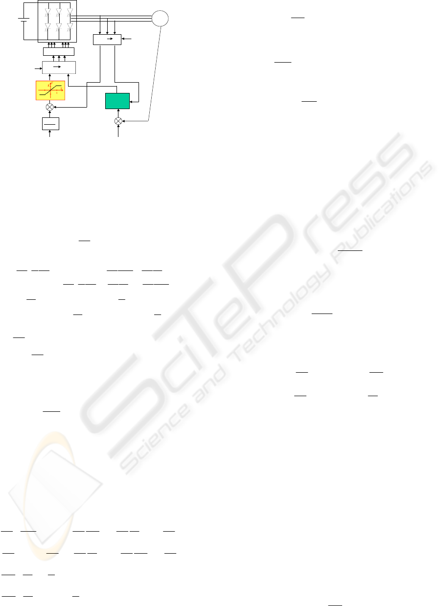
The system is an induction machine fed by a PWM
voltage source inverter. The sliding mode controllers
are applied to the inverter via reference voltages
(Fig. 1).
222
Faqir A., Pinchon D., Ramanou R. and Mahieddine S. (2007).
DISCRETE DYNAMIC SLIDING SURFACE CONTROL FOR ROBUST SPEED CONTROL OF INDUCTION MACHINE DRIVE.
In Proceedings of the Fourth International Conference on Informatics in Control, Automation and Robotics, pages 222-227
DOI: 10.5220/0001621602220227
Copyright
c
SciTePress
SMC
DSSC
r
Ω
i
dsc
PWM Signals
IM
r
Ω
1+sT
r
L
m
()
ref
r
Ω
r
φ
s
θ
A,b,c d,q
i
ds
i
qs
V
qs
V
ds
s
θ
d,q A,b,c
i
a
i
b
i
c
v
a
v
b
v
c
Figure 1: Discrete Sliding Surface Control structure of an
induction machine.
2.1 Induction Machine Model
For the study of the induction machine, we take the
following model:
BUAX
dt
dX
+= (1)
with
(
)
(
)
⎥
⎥
⎥
⎥
⎥
⎥
⎦
⎤
⎢
⎢
⎢
⎢
⎢
⎢
⎣
⎡
−−
−
−−
−
−
+−−
−−−
+−
=
r
T
sl
r
T
m
L
sl
r
T
r
T
m
L
r
T
m
L
r
m
L
r
T
s
T
s
r
m
L
r
T
m
L
s
r
T
s
T
A
1
0
1
0
1111111
1111111
ω
ω
σ
σ
ω
σ
σ
σ
σ
σ
ω
ω
σ
σ
σ
σ
ω
σ
σ
σ
⎥
⎥
⎥
⎥
⎦
⎤
⎢
⎢
⎢
⎢
⎣
⎡
=
00
00
1
0
0
1
s
L
s
L
B
σ
σ
,
⎥
⎥
⎥
⎦
⎤
⎢
⎢
⎢
⎣
⎡
=
qr
dr
qs
i
ds
i
X
φ
φ
and
⎥
⎦
⎤
⎢
⎣
⎡
=
qs
v
ds
v
U
Where
⎟
⎠
⎞
⎜
⎝
⎛
−=
r
L
s
L
m
L
2
1
σ
.,
r
sl
sr
p
r
ωωωω
+=Ω=
The stator voltages
(
)
qs
v
ds
v ,
are considered as
control inputs, while the stator currents
(
)
qs
i
ds
i ,
, the
rotor flux
(
)
qr
dr
φφ
,
and the speed
(
)
r
Ω
are
considered as state variables.
From the equations (1), the following electrical
equations are deduced:
11 1
(2)
111
(3)
1
(4)
1
(5)
di
RLL
ds sm m m
ii v
sqs r qr
ds dr ds
dt L L T L L L L
ssrrsrs
di
RL L
qs
sm m m
ii v
sqs r qrqs
ds dr
dt L L L L T L L
ssr srr s
d
L
dr m
i
qr
ds dr sl
dt T T
rr
d
L
qr
m
i
qs qr
sl dr
dt T T
rr
ωφωφ
σσσσ
ωωφφ
σσ σ σ
φ
φωφ
φ
ωφ φ
−
=++ + +
=− − − + +
=−+
=−−
⎧
⎪
⎪
⎪
⎪
⎨
⎪
⎪
⎪
⎪
⎩
With
r
R
r
L
m
L
s
R
sm
R
2
2
+=
The mechanical model is given by:
r
f
K
L
T
em
T
dt
r
d
J Ω−−=
Ω
(6)
And the electromagnetic torque can be expressed as:
()
ds
i
qrqs
i
dr
r
L
m
pL
em
T
φφ
−=
(7)
2.2 Field Oriented Control
The field orientation is obtained by imposing:
⎩
⎨
⎧
=
=
0
qr
r
dr
φ
φφ
(8)
From the equations (4) and (8), the
ds
i
reference can
be computed in order to impose the flux
r
φ
:
ds
i
r
sT
m
L
r
+
=
1
φ
(9)
Furthermore, the position
s
θ
of the rotating frame
can be estimated using equations (5) and (8):
∫
Ω+=
⎟
⎟
⎠
⎞
⎜
⎜
⎝
⎛
dt
r
p
rr
T
qs
i
m
L
s
φ
θ
(10)
With taking into account the field orientation of the
machine, the stator equations on d-q axis become:
⎪
⎪
⎩
⎪
⎪
⎨
⎧
⎥
⎦
⎤
⎢
⎣
⎡
⎥
⎦
⎤
⎢
⎣
⎡
+++=
−−+=
rr
r
L
m
L
ds
i
ss
L
qs
i
sm
R
dt
qs
di
s
L
qs
V
r
r
L
r
T
m
L
qs
i
ss
L
ds
i
sm
R
dt
ds
di
s
L
ds
V
φωωσσ
φωσσ
(11)
2.3 Decoupling System
Using the system given by equations (11), we can
remark the interaction of both inputs, which makes
the control design more difficult.
The first step of our work is to obtain a
decoupled system in order to control the
electromagnetic torque via stator quadrature current
qs
i
such as a DC machine.
A decoupled model can be obtained by using two
intermediate variables:
d
emf
ds
v
ds
v +=
1
(12)
q
emf
qs
v
qs
v +=
1
(13)
where
rr
R
r
L
m
L
qs
i
s
L
s
d
emf
φσω
2
+=
(14)
DISCRETE DYNAMIC SLIDING SURFACE CONTROL FOR ROBUST SPEED CONTROL OF INDUCTION
MACHINE DRIVE
223
and
qs
i
r
T
r
L
m
L
r
r
L
m
L
s
ds
i
s
L
sq
emf
2
+−−=
φωσω
(15)
⎥
⎦
⎤
⎢
⎣
⎡
⎥
⎦
⎤
⎢
⎣
⎡
−
=
qs
i
ds
i
M
qs
v
ds
v
1
1
1
⎥
⎦
⎤
⎢
⎣
⎡
=
L
L
M
0
0
with
s
r
T
r
L
s
L
m
L
r
T
r
L
s
R
r
T
r
L
L
σ
++
=
2
(16)
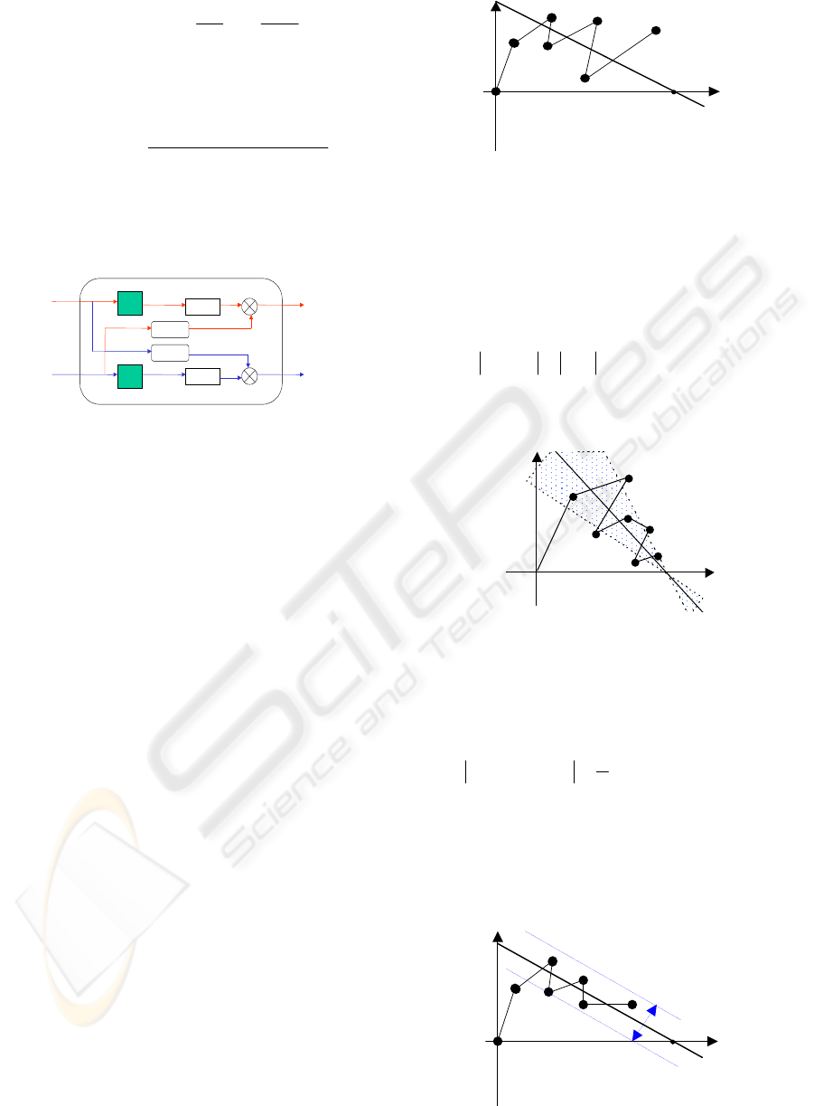
The stator voltages
(
)
qs
v
ds
v
, are reconstituted from
(
)
1
,
1
qs
v
ds
v
(Fig. 2):
1/L
1/L
i
ds
i
qs
v
ds
v
qs
+
-
+
v
qs1
v
ds1
emf
d
emf
q
-
Figure 2: Decoupling control.
3 DISCRETE SLIDING SURFACE
CONTROL
3.1 General Concept
Since Dr. Utkin proposed the variable structure
system (VSS), it had been widely discussed and
applied in many control systems. Due to the change
of the switching gains in control function, the
controlled system can vary its own controller
according to the external condition. Hence, VSS is
robust to against to the system‘s parameter variation
and external disturbance. VSS owns one sliding
surface predetermined according to the desired
dynamic character. Once the sliding mode locking
on the sliding surface, the system response will be
directed by this surface. The existence condition of
classical sliding mode in continuous system is
0SS <
(17)
Change the differential equation to difference
equation. When applying the condition to discrete
systems, the existence condition becomes to
() ( )
(
)
[]
0kS1kSkS <−+
(18)
However, the system is controlled by the controller
only in each sampling time. The controller can not
modify the response during the sampling interval. It
may happen that the condition (18) is not only
satisfied but also the sliding motion is divergent. It is
shown in fig 3.
Phase Plane
S(k)
S(k+1)
S(k+2)
S(k+3)
Ω
ref
Figure 3: Discrete sliding mode.
The condition (18) only makes the sliding motion
toward to the sliding surface. However, it can not
guarantee the sliding mode convergent to this
surface. The condition (18) is only the necessary
condition not the sufficient condition in discrete
systems. To make up the drawback, we introduces
one additional restriction, that is
(
)
(
)
kS1kS <+
(19)
Combining equation (18) and (19) can make sure the
sliding motion convergent. However, the sliding
surface is changed to sliding region shown in fig 4.
S(k)
Phase Plane
S(k+1)
S( k+ 2)
S(k+3)
Figure 4: Discrete sliding mode with sliding region.
The choice of switching gain becomes three states.
This change causes some difficulty in
implementation of hardware. To maintain the binary
choice, one restriction of different viewpoint, that is
()()
2
kS1kS
ξ
<−+
(20)
where
ξ
is a small positive constant. The varying of
each step of sliding motion is restricted. Then,
condition (18) makes the sliding mode toward to the
surface. The condition (20) makes the sliding motion
oscillated on this surface within a small range
ξ
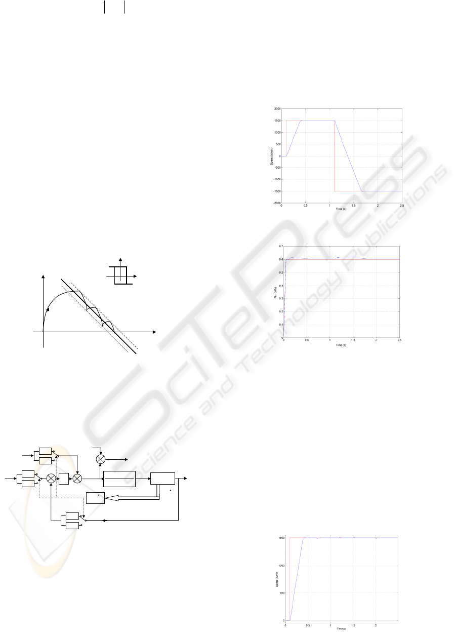
shown in fig 5.
Phase Plane
S(k)
S(k+1)
S(k+2)
S(k+3)
Ω
ref
ξ
Ω
Ω
Figure 5: New discrete sliding mode.
ICINCO 2007 - International Conference on Informatics in Control, Automation and Robotics
224
This new sliding mode is
()
ξ<kS
different to the
classical sliding mode
(
)
0kS =
. Hence, this new
sliding mode is called “non-ideal sliding mode.”
This paper will prove that if the controller makes the
system‘s solution of classical sliding mode
asymptotically stable, then the same controller
makes the solution of non-ideal sliding mode
asymptotically stable, too. Hence, the discussion of
non-ideal sliding mode can be done like classical
sliding mode. Just like the classical sliding mode,
the system’s dynamic character is directed by the
surface only when the sliding motion is within the
range of
ξ
. To reduce the time of out of control, the
high switching gain is usually chosen to speed up the
reaching time. However, in discrete systems the
controller only modifies the control signal at each
sampling time. High switching gains can speed up
the reaching time, but the chattering often be
enlarged. To eliminate the chattering and decrease
the reaching time, this paper introduces the dynamic
sliding surface control (DSSC) rule shown in fig 6.
u = U
min
u=U
max
S(k) = 0
U
S(k)
ref
Ω
Ω
Ω
Figure 6: Discrete sliding mode with dynamic sliding
surface.
5 SIMULATION RESULTS
S(
Ω
,
Ω
)
Ω
V
qs1
p.L
m
.
φ
r
.L
r
R
s
.L
r
2
+ R
s
.L
r
2
T
em
H=1
Ω
ref
+
-
K
i
/s
1/J.s+F
H=-1
G=1
G=-1
+
m
1
-1
u
2
u
1
Ω
,
Ω
V
qs
fem
q
-
+
-
Figure 7: Scheme of speed sliding mode regulation.
The proposed scheme has been simulated using
parameters given in the appendix.
The first simulation realized on the AC machine
consists in step variation of the reference. Indeed,
(Fig. 8) and (Fig. 9) represent the speed and the rotor
flux when reference step is first imposed and then an
inversion is imposed.
In (Fig. 9) it is clearly shown for rotor flux responses
that the decoupling is realized since the direct
component of the rotor flux converges to the
reference
(
)
ref
r
φ
, and its quadrature component to
zero despite the reference variations. Furthermore
we can remark that the proposed control scheme
presents good tracking capacities since there is no
overshoot and no static error (Fig. 8).
Figure 8: Speed response.
Figure 9: Rotor flux components responses.
(Fig. 10) represents the dynamic response of the
speed for different values of the load torque. First
when the speed reaches its reference value (1500
tr/min), a step of load torque is applied at (t=0.7 s).
The electromagnetic torque rises to the new value of
the load torque (Fig.11), and the speed is not
disturbed. Then when the load torque is decreased to
zero (t=1.2 s) or to a negative value (t=1.5 s) the
speed stays on the reference value.
It is clearly shown from the results that the control
scheme presents good regulation capacities. Indeed,
the external disturbances such as load torque
variations are rejected by control system.
Figure 10: Speed response to load torque variations.
DISCRETE DYNAMIC SLIDING SURFACE CONTROL FOR ROBUST SPEED CONTROL OF INDUCTION
MACHINE DRIVE
225
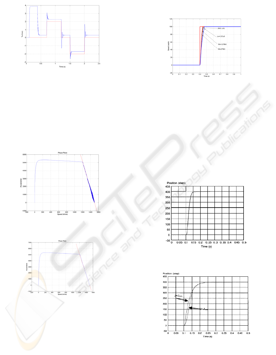
Figure 11: Electromagnetic torque responses to load
torque variations.
(Fig. 12) and (Fig. 13) illustrate the dynamic
response in the phase plane respectively with a
normal sliding surface control and with a dynamic
discrete sliding surface control.
We can note the apparition of the chattering
phenomenon (Fig. 12) with the normal sliding
surface control due to the discontinuous
characteristic of this function.
Figure 12: Response in the phase plane with the normal
sliding surface control.
Figure 13: Response in the phase plane with dynamic
discrete sliding surface control.
(Fig. 14) depicts the drive response for different
values of the rotor constant time.
It is important to note that the changing parameters
are introduced only in the model of the machine.
The controller is not involved by these variations.
It is well-known for classic controller that the
indirect field oriented control is very sensitive to the
rotor constant time variations.
The results shown on (Fig. 14) confirm the
robustness quality inherent to the proposed
controller. Indeed, there is no overshot whatever the
rotor constant time
Figure 14: Robustness test of the sliding mode control.
6 EXPERIMENTAL RESULTS
Figs. 15 and 16 show the experimental evolution of
the position and the experimental phase plane
trajectory when the sliding condition is just
validated: |c_| = |s1p|. It can be seen that the step
reference of 400 steps is reached for t = 0.08 s
without overshoot or steady-state error and that there
are almost three commutations to reach the
reference.
Figure 15: Position and reference (400 steps).
Figure 16: Position and reference for two different
inertias.
ICINCO 2007 - International Conference on Informatics in Control, Automation and Robotics
226
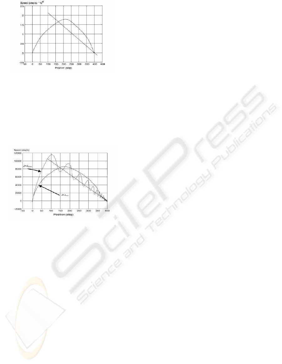
Figure 17: Phase plane trajectory.
Figs. 17 and 18 show the evolution of the position
and the phase plane trajectories for two different
inertias (J = Jmin = 0.0023 kg.m
2
and J = Jmax =
0.013485 kg.m
2
).
By comparing the two responses, it can be noted that
the reference is always reached without any
overshoot or steady-state error whatever the inertia
of the drive.
Figure 18: Phase plane trajectory for two different inertias.
From these results, it can be seen that the robustness
of the proposed approach between external
disturbances and plant parameter variations is
experimentally validated.
7 CONCLUSION
In this paper, we have shown that by using a sliding
mode control applied to an IFOC, a high-precision
positioning of an IM shaft can be achieved whatever
the mechanical configuration of the load is. Indeed,
the position reference is obtainedwithout any
overshoot or static errorwhatever the inertia or the
load torque are. Furthermore, it has been shown that
the chattering problem around the switching surface
can be alleviated using the VSC approach with
LFSG. Therefore, the proposed solution can be
considered very suitable for induction drive used in
robotics or in numerical control of machine tools.
REFERENCES
M.O. Mahmoudi et al, Cascade sliding mode control of a
field oriented induction machine drive, EDP Sciences
(1999).
Guy Grellet, Guy Clerc, Actionneurs elctrique
(EYROLLES, France, 1997).
Vadim I.Utkin, IEEE Transactions on industrial
electronics (Vol 40, No 1, 1993)
H. Bühler, Réglage par mode de glissement (Presses
polytechniques romandes, Switzerland, 1986).
F. Chen and M. W. Dunnigan, “Sliding-mode torque and
flux control of an induction machine,” Proc. IEE
Electric Power Appl., vol. 150, no. 2, pp. 227–236,
Mar. 2003.
P. DeWit, R. Ortega, and I. Mareels, “IFOC of
inductionmotors is robustly globally stable,”
Automatica, vol. 32, no. 10, Oct. 1996.
Abdel Faqir, “Position Control of an Induction Machine
Using Variable Structure Control”, thesis (2003).
S. Ferreira Pinto, Sliding mode control of matrix
converters with lead-lag power factor, EPE (2001).
E. Etien, Real time induction motor drive using sliding
mode linearization, EPE (2001).
Jesus Arellano-Padilla, Robust fuzzy-sliding mode control
for motor drives operating with variable loads and pre-
defined system noise limits, EPE (2001).
LIST OF PRINCIPAL SYMBOLS
p
: Number of pole pairs.
rs
RR , : Stator and rotor resistance.
rs
LL , : Stator and rotor inductance.
:
r
T
Rotor time constant.
m
L : Magnetizing inductance.
qsds
ii , : Stator currents in d-q rotating reference
frame.
qsds
vv , : Stator voltages d-q rotating reference
frame.
qrdr
φ
φ
, : Rotor fluxes d-q rotating reference frame.
r
ω
: Rotor speed.
e
T : Electromagnetic torque.
s
θ
: Angular position.
s : Laplace operator
(
)
dtd /
.
σ
: Coefficient of dispersion.
J : Total rotor inertia constant.
DISCRETE DYNAMIC SLIDING SURFACE CONTROL FOR ROBUST SPEED CONTROL OF INDUCTION
MACHINE DRIVE
227
