ULTRA VIOLET IMAGING TRANSDUCER
CONTROL OF A THERMAL SPRAYING ROBOT
D. Breen, E. Coyle and D. M. Kennedy
Faculty of Engineering, Dublin Institute of Technology, Dublin, Ireland
Keywords: Thermal spraying, robot control, ultraviolet lighting, image processing.
Abstract: The thermal spraying industry has a global market of $1.3 billion. This industry relies heavily on manual
operation of the thermal spraying equipment or in some cases, robotic systems that require costly set up of
material for surface coating and time consuming trajectory planning. The main objective of this research
was to investigate novel ideas for automating the thermal spraying process. This requires transducers that
can provide information about arbitrarily shaped and orientated material for spraying and generating the
trajectory plan for the robot manipulator during the thermal spraying process in real time. The most
significant difficulty for any transducer, particularly low cost vision systems is the thermal spraying process
which in our research is molten material such as aluminium in an Oxy-Acetylene flame with temperatures
exceeding 3100
0
C. This paper outlines the concept and based on the experimental results presented
demonstrates combined optical and image processing techniques for obtaining information about objects
behind a butane flame.
1 THERMAL SPRAYING ROBOT
1.1 Introduction
Thermal spraying robotic research is concerned with
investigating a number of novel ideas, which will
contribute to the autonomous control of an
articulated thermal spraying robot manipulator. This
control of the thermal spraying process, which is
used in the application of wear, corrosion and
thermal barrier surface coatings will improve safety,
efficiency and costs in the surface coating industry.
Thermal spraying has an estimated global
mark
et of $1.3 billion dollars (AZoM). The
operation of thermal spraying equipment requires
the consideration of health and safety issues.
1.2 Health and Safety
In industrial applications, thermal-spraying
equipment is normally enclosed in specialist
enclosures designed to reduce noise, fumes and
observation via safety equipment by operators from
a safe location. R&D may not have these specialist
enclosures. Therefore health and safety risks must be
managed via appropriate health and safety
equipment and procedures. Powder Flame spraying
with an Oxy-Acetylene torch which is the system
used in this research produces intense bright flames
with a peak temperature in excess of 3,100
0
C.
Two-wire electric arc and plasma spraying
syste
ms produce UV-B and UV-C with their
associated health and safety risks to the operator.
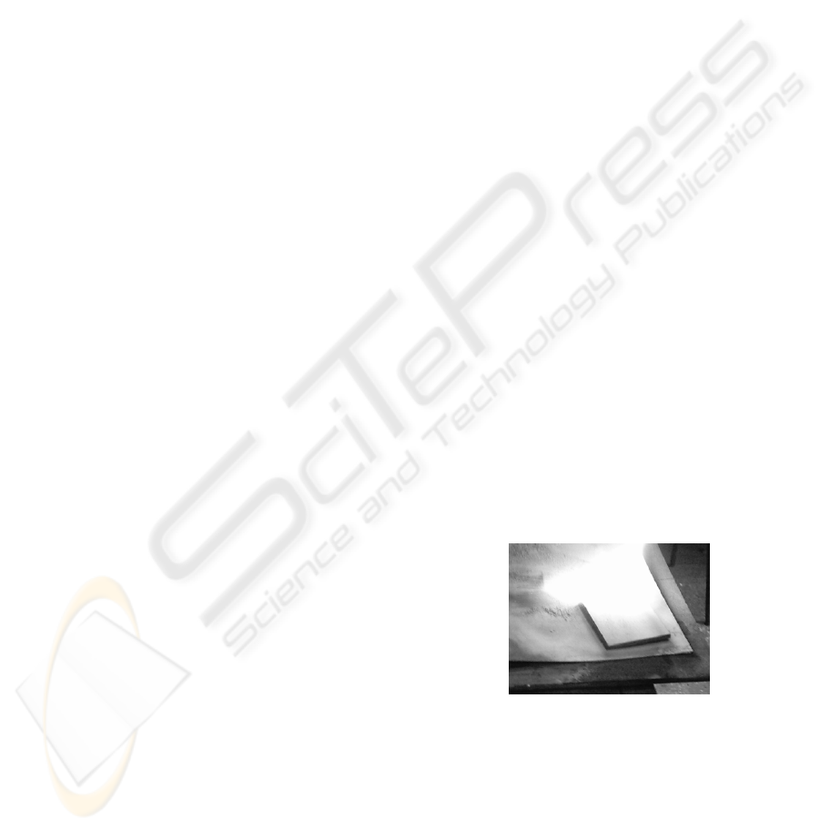
Figure 1 shows a typical flame from the thermal
spraying process.
Figure 1: Thermal Spraying Process Flame.
The research presented in this paper uses UV-A
lighting which is also present in the thermal spraying
process.
1.3 Robot Control
The control of a robot manipulator requires
information about the kinematics and dynamics of
the robotic system being used for the thermal
412
Breen D., Coyle E. and M. Kennedy D. (2007).
ULTRA VIOLET IMAGING TRANSDUCER CONTROL OF A THERMAL SPRAYING ROBOT.
In Proceedings of the Fourth International Conference on Informatics in Control, Automation and Robotics, pages 412-417
DOI: 10.5220/0001622104120417
Copyright
c
SciTePress
spraying system. Information about the position and
orientation of the thermal spraying torch tip at
different locations along the object to be sprayed and
at different times which is known as trajectory
planning is produced. This information is supplied
into the robotic control system, which is used by the
inverse kinematic equations and dynamic equations
of motion to move the robot actuators to the desired
locations. Thermal spraying automation provides
this trajectory planning information via pre-
programming for specific objects, which is time-
consuming and costly.
The autonomous analysis of the position and
orientation of the thermal-spraying torch, which
would allow the spraying of unspecified objects at
unspecified orientations, would significantly reduce
set-up times and costs. However this level of
automation is significantly hampered by the thermal
spraying process. It is quite clear that the intense
flame would hamper many object-measuring
systems which could be used to obtain in real time,
the position and orientation of the thermal spraying
torch information. If however the flame could be
removed from the scene and a low cost camera used
to view the object with associated distance
measuring techniques, this would accommodate the
autonomous control of the thermal spraying process.
This research attempts to provide a possible
solution to this difficult requirement.
2 FLAME REMOVAL
2.1 Ultra Violet Lighting
During the research on measuring the distance to
objects with a low cost infra red laser and
monochrome camera the problem of the thermal
flame became a key issue. It was decided to
investigate the use of a monochromatic light source
and band pass filter to remove the thermal spraying
flame. It was decided to use the UV-A spectrum
(350 nm - 400 nm) as an initial area for research
because it is reasonable to assume there is the full
visible normal lighting (400 nm – 750 nm) and infra
red ( 750 nm – 1 mm) in the thermal spraying scene
and environment.
The light source used was a black light
fluorescent lamp used in dance halls which has an
amount of 387 nm wavelength light which matches
our band pass filter.
2.2 Camera and Filter Spectral
Response to Ultra Violet
A key aspect of the research was to use standard low
cost equipment. The first objective was to ensure
that the low cost monochrome camera has a
response under ultra violet lighting, as the data sheet
did not even provide data below 400 nm (Samsung).
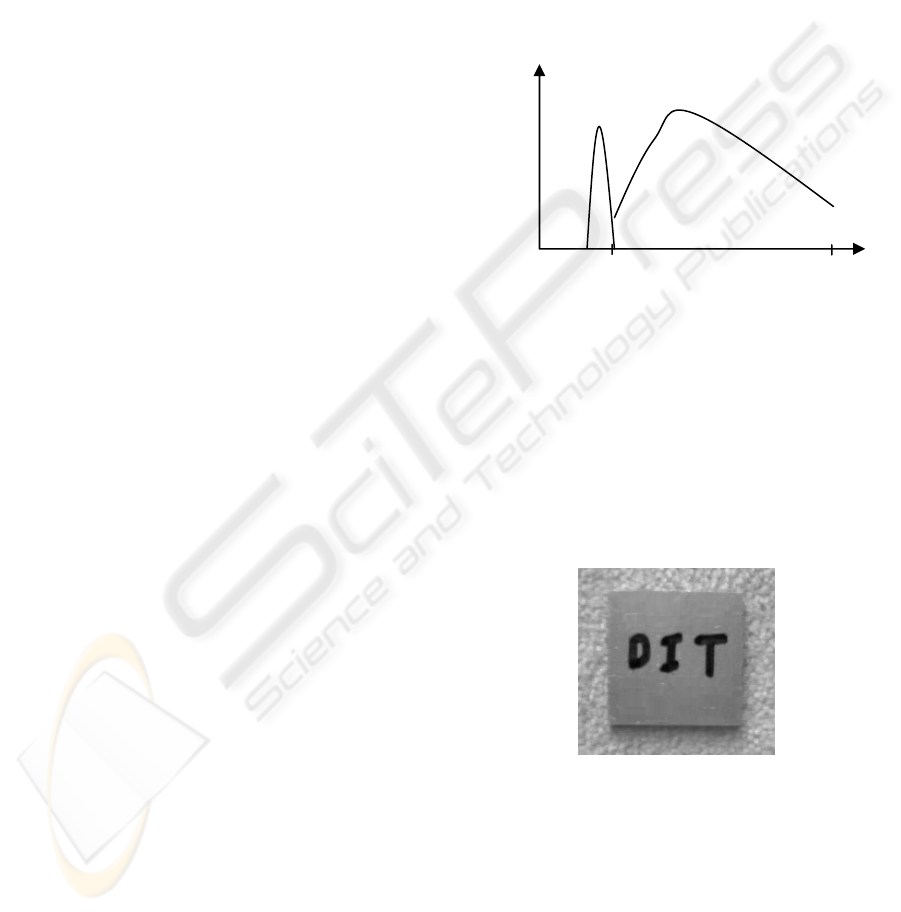
A 387 nm narrow band pass filter was used. Figure 2
shows the camera and filters relative spectral
responses.
Figure 2: Camera and filter spectral response.
2.3 Ultra Violet Camera and Filter
A small piece of aluminium metal 50 mm x 60 mm
with the letters D I T of height 15 mm written on it
was used as a test piece. The test piece under
internal daylight is shown in Figure 3. The test piece
of aluminium with DIT and the background are clear
and distinct.
Figure 3: Test piece of Aluminium.
A 387 nm filter was placed in front of the
camera under internal daylight and the result is
shown in Figure 4. The result shows a complete lack
of response from the camera.
400
700
Wavelength nm
1
0.5
Camera response
387 nm Filter
Spectral
response
ULTRA VIOLET IMAGING TRANSDUCER CONTROL OF A THERMAL SPRAYING ROBOT
413
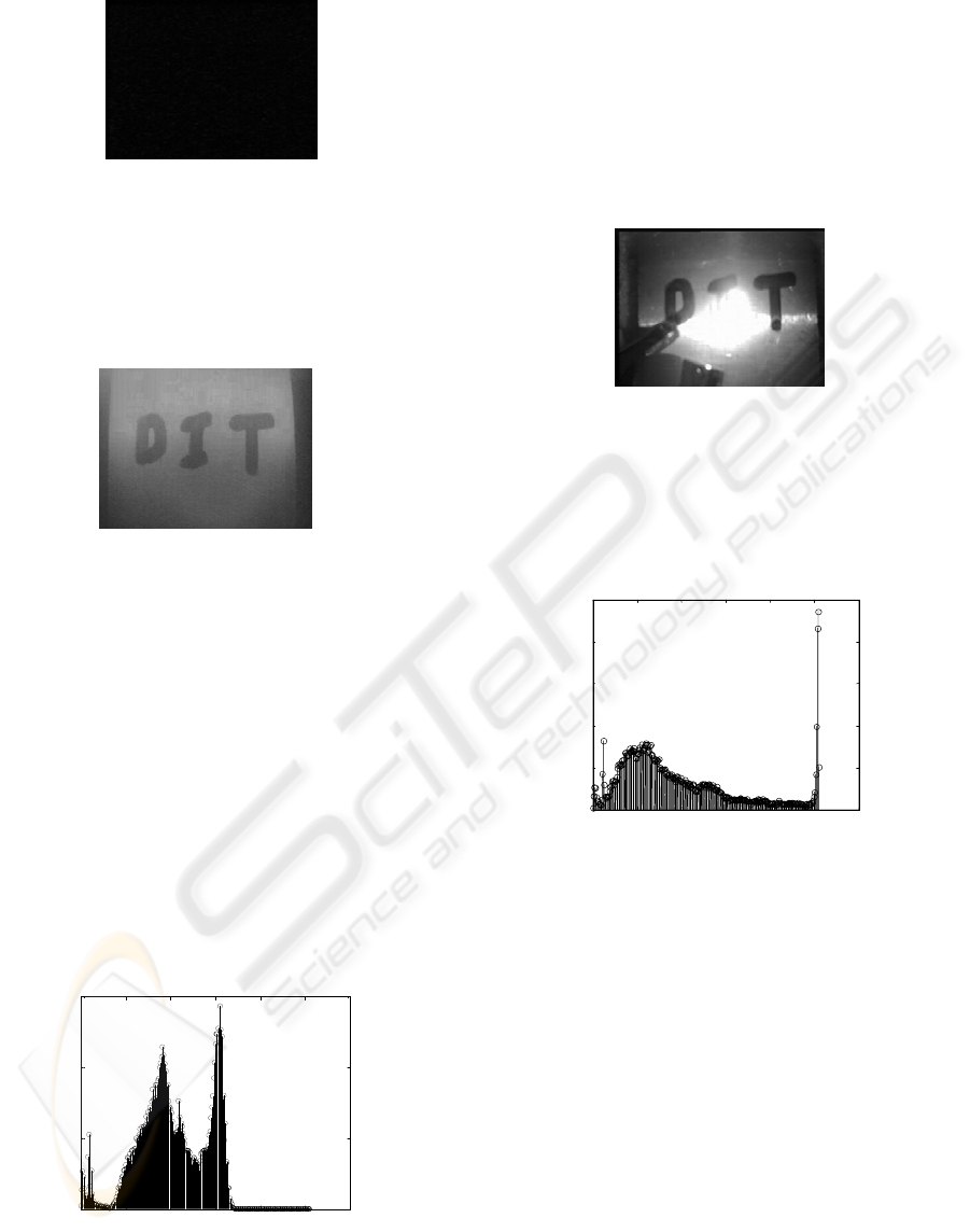
Figure 4: Camera response internal daylight and 387 nm
filter.
A black light fluorescent lamp, which has a
certain amount of 387 nm wavelength light, was
then switched on and the cameras response is shown
in Figure 5.
Figure 5: Camera response to filtered 387 nm lighting.
0 50 100 150 200 250 300
0
500
1000
1500
2000
2500
Flame on indoor daylight histogram
Intensity value 0 - 255
Nu
m
be
r
of
pix
Due to the low intensity of 387 nm lighting, the
camera was moved closer to the test piece. The
background to the test piece is shown as dark stripes
to the left and right of the image. The response of
the camera clearly shows the letters D I T.
els
The monochrome image pixels have dynamic
range values between 0 and 255. The response of the
camera in this experiment provides a low dynamic
range image. Using Matlab
TM
this low dynamic
range is shown quantitatively by its histogram in
Figure 6. There are no intensity values between 185
and 255, however there is good separation between
the letters DIT and the background shown by the dip
in the histogram at an intensity value of 133.
Figure 6: 387 nm image histogram.
The low dynamic range response is due not
only to the response of the camera but from the lack
of 387 nm intensity in the black light and the 387 nm
filters attenuation effect.
2.4 Flame Removal from Image
Using a small butane lighter flame in front of the test
piece under daylight lighting produces the image
shown in Figure 7.
Figure 7: Daylight with flame.
Clearly image information behind the flame is
completely obliterated because of the saturation
effects of the flame on the cameras photo sensors,
which is shown quantitatively in the images
histogram in Figure 8.
Figure 8: Flame on daylight histogram.
The histogram shows 8.2% of the pixels in the
image have what we would consider saturated values
between 250 and 255, which are caused by the
butane flame. It would be extremely difficult to
obtain information from behind the flame such as
the area or centroid in pixels of the letter I in this
image.
0 50 100 150 200 250 300
0
500
1000
1500
387 nm image histogram
Intensity value 0 - 255
Number of pixels
The main developments reported in this paper
will detail a process for obtaining this and other
information about the letter I, a process which could
be developed and applied to the thermal spraying
control process.
Placing the 387 nm filter in front of the camera
and turning on the black light with the butane flame
on produces the image shown in Figure 9.
ICINCO 2007 - International Conference on Informatics in Control, Automation and Robotics
414
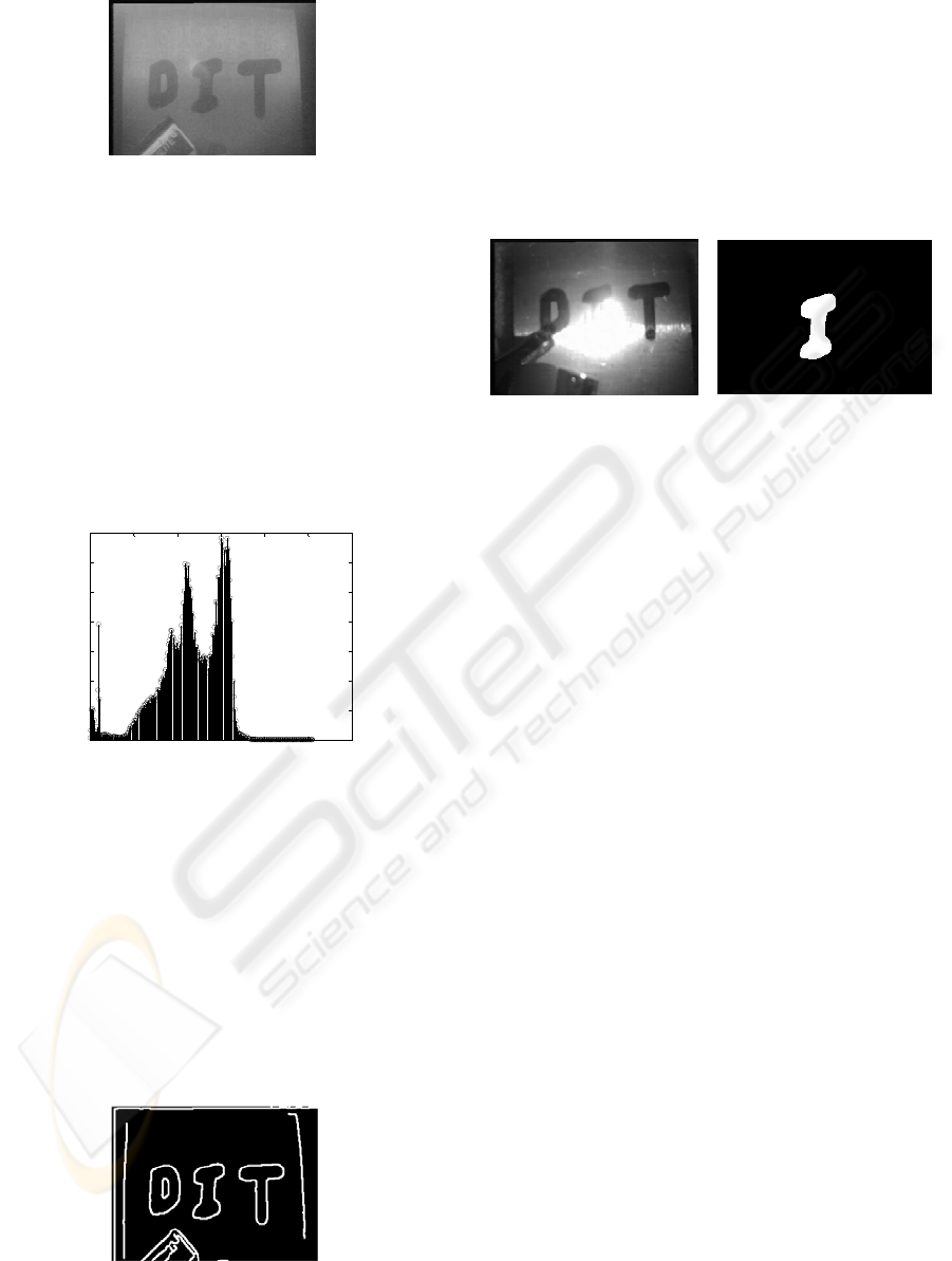
Figure 9: 387 nm lighting flame on.
This technique was extremely encouraging, as
the letters D I T are clearly visible. There is a slight
transmission of flame intensity just above the letter
I. Letters on the butane torch are also visible. Figure
10. is a histogram of the flame on in the 387nm
image.
The histogram for the image shown in Figure
10 suggests this is a low contract image and there is
considerable room for improving image information
(contrast) above pixel value 185. This could be
achieved by increasing the intensity of the 387 nm
lighting source.
Figure 10: Flame on 387 nm image histogram.
3 IMAGE PROCESSING
3.1 Canny Edge Setection
Using the Matlab
TM
image processing toolbox the
image in Figure 9 was processed using the canny
edge detector with a Gaussian filter standard
deviation value of 1.5 and high-low threshold values
of 0.16 and 0.064 respectively which produced an
edges image shown in Figure 11.
Figure 11: Edges image.
The edges image in Figure 11 was image
processed further to remove the perimeter objects
using the Matlab function imclearborder
leaving only the letters D I T. Using the Matlab
TM
functions for labelling, selecting and infilling the
letter I, bwlabel, bwselect and imfill the
letter I was extracted as shown in Figure 12. For
contrast the flame image is shown beside the
extracted letter I
Figure 12: Flame on and extracted letter.
3.2 Feature Extraction
Using the Matlab
TM
image processing toolbox and
0 50 100 150 200 250 300
0
200
400
600
800
1000
1200
1400
Flame on 387 nm filter and blacklight histogram
Intensity value 0 - 255
Number of pixels
the Matlab
TM
function regionprops a number of
characteristics for the letter I were obtained. Some of
these features are:
Area 2561 pixels
Centroid 131, 112 measured
from top left corner
Eccentricity 0.9148
Orientation 83
0
Perimeter 264 pixels
From analysis of the above, it is a
straightforward process to obtain accurate real world
values from image pixel values for actuating a robot
manipulator using perspective transformations,
inverse kinematics and camera calibration
techniques.
4 THERMAL SPRAYING
SPECTRA
4.1 Thermal Spraying Process
To determine the band pass filter and lighting
wavelength for the removal of the thermal spraying
flame and combustion material spectrum in the
thermal spraying process would require extensive
testing and the purchase of a range of filters. The
reason for this is that there are a number of thermal
spraying processes such as powder, arc, plasma and
ULTRA VIOLET IMAGING TRANSDUCER CONTROL OF A THERMAL SPRAYING ROBOT
415
a vast range of surface coating materials all
producing their own combustion spectra
The following is a list of some of the more
common surface coating materials.
Tungsten carbide/cobalt
Chromium carbide/nickel chromium
Aluminium bronze
Copper nickel indium
Hard alloys of iron
To apply this technique of using
monochromatic ultra violet lighting and narrow band
pass filter to remove the combustion process,
theoretical research into the spectrum produced by
the specific process where autonomous control
would be beneficial is required. The reason for this
is that the emission spectra of flames is sensitive to
(Zirack):
temperature
gas/air or gas/oxygen mixture ratio
gas purity
burner type
gas flow (laminar or turbulent)
coating materials
height of observation in the flame
Research can however provide reasonable
indicators of a location for the band pass filter and
where spectral problems may arise. The thermal
spraying process used for this research was powder
thermal spraying using an Oxy-Acetylene torch.
4.2 Oxy-Acetylene Flame
The Oxy-Acetylene flame is a chemical reaction
resulting from the combination of acetylene C
2
H
2
with oxygen 0
2
. Figure 13 shows the two stages of
the chemical reactions (Materials Engineering
Group, MEG)
+
Figure 13: Oxy-Acetylene flame.
A neutral flame with products of combustion
CO
2
and H
2
O is produced with maximum heat
output when equal quantities of oxygen and
acetylene are used (MEG). Controlling this mixture
would form part of the overall thermal spraying
robot control system.
This is an idealised view and many other
ordinary molecules and unstable radicals are
produced in an Oxy-Acetylene flame in air.
4.3 Oxy-Acetylene Emission Spectra
The visible spectrum runs from 400 nm to 750 nm
and the infra red spectrum runs from 750 nm to 1
mm (HyperPhysics). This suggests a portion of the
ultra violet spectrum between 350 – 400 nm
commonly known as the UV-A spectrum for the
research as it excludes the visible and infra red
spectrum.
Research is now concentrated on identifying
weak spectra between 350 nm and 400 nm from the
powder flame spraying Oxy-Acetylene in air flame
with a range of molten surface coating materials,
which is widely used in the powder spraying
industry.
The ordinary molecules which are the stable
products of combustion, H
2
0
2
, C0
2
, C0, 0
2
or N
2
in
hydrogen flames do not provide spectra of any
appreciable strength in the visible or ultra violet
spectrum (Zirack).
The only product of combustion that may have
an appreciable spectrum in the UV band is the
hydroxyl radical OH which give band peaks at 281
nm 306 nm and 343 nm. Oxyacetylene flames not
only produce spectra of hydrogen flames but also
emit radiation of hydrocarbon radicals. Between the
350 nm and 400 nm wavelengths a weak CH band
occurs at 387/9 nm and a strong band at 432 nm are
found in air acetylene flames.
This suggests many wavelengths between 350
and 400 nm may be suitable for removing the Oxy-
Acetylene flame in air but we must add the spectrum
from the surface coating material to ensure there is
no appreciable interference from the molten material
in our chosen UV band. This is an area for continued
research. However a review of published work by
De Saro relating to emission spectra of molten
elements such as aluminium and copper provides
information on spectra of interest as follows:
Oxygen 0
2
Acetylene C
2
H
2
Stage 1
C
2
H
2
0
2
= 2C0 +H
2
Stage 2
C0 + H
2
+ 0
2
= C0
2
+ H
2
0
Aluminium 390 – 400 nm
Iron 260 – 262 nm
Magnesium 380 - 385 nm
Copper 320 – 330 nm
Results so far suggest using a narrow band pass
filter and lighting between 350 and 370 nm
ICINCO 2007 - International Conference on Informatics in Control, Automation and Robotics
416

In addition to the interference from the
emission spectra, an added complication is the
molten material itself. This will act as a dust cloud
and have the effect of reducing contrast in the
image.
The image processing techniques necessary for
this research are those associated with low contrast
images and reconstructing edges and shapes such as
those provided by techniques like the Hough
transform. (Young)
5 CONCLUSION
This paper has detailed a system of combining
optical filtering and image processing which can be
used to obtain information about low contrast
objects behind or within a test butane flame.
The paper also suggests a region within the
UV-A spectrum, which shows promise for
implementing ultra violet image control of a
thermal-spraying robot. Further work on identifying
the spectra of a greater range of surface coating
materials is required.
The ability to see through a flame could have
benefits in other industries such as the fire fighting
service and welding. The system detailed could be
fitted as a single eye head up display or fitted to a
small mobile robot where there are low smoke flame
environments.
REFERENCES
AZoM, Thermal Spraying – An Overview,
http://www.azom.com/detailes.asp?AtricleID=511
(last accessed January 2007).
DeSaro R, Weisberg A, Craparo J. 2005, In Situ, Real
Time Measurement of Melt Constituents in the
Aluminium, Glass and Steel Industries, Energy
Research Co., Staten Island New York.
England, G.,. “Wear Resistance”
http://www.gordonengland.co.uk/wear.htm (last
accessed January 2007)
HyperPhysics,
http://hyperphysics.phyastr.gsu.edu/hbse/ems3.html
(last accessed January 2007)
Materials Engineering Group, Oxy-Gas Welding,
http://www.meg.co.uk/meg/app04.htm (last accessed
January 2007)
Matlab
TM
. http://www.mathworks.com (last accessed
january 2007)
Samsung 1/3 CCD image sensor for CCIR cameras,
http://www.datasheetcatalog.com/datasheets_pdf/K/C/
7/3/KC73129MP.shtml
(last accessed January 2007).
thefabricator.com, Theraml spray safety and OSHA
compliance, (last accessed January 2007)
http://www.thefabricator.com/Safety/Safety_Article.cfm?I
D=45
Young, David, 1995, Hough transforms,University of
Sussex, Brighton, U.K.
http://homepages.inf.ed.ac.uk/rbf/CVonline/LOCAL_
COPIES/YOUNG/vision4.html
(last accessed January
2007)
Zirak Giorgio, 2000, Flame Emission Spectroscopy:
Fundamentals and Applications, NILES University of
Cairo,Egypt
ULTRA VIOLET IMAGING TRANSDUCER CONTROL OF A THERMAL SPRAYING ROBOT
417
