
DESIGN OF AN AUTOMATED FIXED BED REACTOR USED
FOR A CATALYTIC WET OXIDATION PROCESS
A. El Khoury, B. Bejjany
Laboratoire de Chimie Industrielle – Génie des Procédés (EA21), Cnam, 2 rue Conté, Paris III, France
M. Debacq, A. Delacroix
Laboratoire de Chimie Industrielle – Génie des Procédés (EA21), Cnam, 2 rue Conté, Paris III, France
Keywords: Wet Air Oxidation, WAO, Data acquisition, Intelligent sensor module, Regulation, Supervision,
Monitoring.
Abstract: Treatment of polluted industrial wastes is one of the challenging research topics that occupy an important
position in various chemical processes. Wet Air Oxidation (WAO) is one of the emerging processes suited
for the treatment of special aqueous wastes. The system consists of an oxidation in the liquid phase of the
organic matter by molecular oxygen at high temperature (200-325°C) and high pressure (up to 175 bar). It is
an enclosed process with a limited interaction with the environment as opposed to incineration. In this
paper, we will discuss the setup and the design of an automated fixed bed reactor used for wet oxidation of
various types of wastes. The system is controlled by a set of intelligent sensor modules used for data
acquisition. Regulation loops integrated within the sensor modules had been developed in order to control
the gas flow, the reactor temperature and the liquid sampling part. The process supervision and monitoring
had been achieved through the deployment of a SCADA software application. The graphical interface
developed for this purpose monitors the major parts of the process.
1 INTRODUCTION
The identification of highly refractory and non-
biodegradable organic pollutants in wastewater,
especially coming from the chemical and
petrochemical industry, has challenged the
conventional wastewater treatment such as
incineration or biological abatement. There is a clear
need to test and set-up an emerging alternative
technology that can deal with highly concentrated
and/or toxic non-biodegradable organic water
pollutants. However, it seems impossible in the close
future to dispose of one universal method able to
destroy all of the detected pollutants at an acceptable
cost (Masende, 2003). Therefore, Wet Air Oxidation
(WAO) is an efficient process by which organic
pollutants can be transformed by oxidation under
high pressures (50-250 bar) and high temperatures
(200-325°C), into carbon dioxide and water (Mishra,
1995). The process can be performed under milder
conditions (temperatures and pressures) by using a
homogenous or heterogeneous catalyst. Catalytic
Wet Air Oxidation (CWAO) is thus an attractive
process for wastewater treatments of toxic pollutants
such as phenol, pesticides, methyl tert-butyl ether
(MTBE) and their intermediate oxidation
compounds (Pintar, 1992).
Several studies with noble metal catalysts,
mainly Ru and Pt supported on carbon, Al
2
O
3
, TiO
2
and CeO
2
have revealed their stability and capacity
to destroy organic pollutants (Imamura, 1988). In
contrast to platinum, ruthenium was found to be an
active metal during the oxidation of acetic acid,
which is very refractory. Comparison of Ru/CeO
2
and Ru/TiO
2
showed that titanium oxide was more
stable in acetic and oxidizing medium, but the
loading of Ce on the catalyst significantly changes
the surface properties resulting in a better dispersion
of the noble metals. Thus, Ruthenium and Cerium
metals supported on alumina are considered to be
stable, accurate and cost effective catalysts
(Oliviero, 2000). There are only some tens of
industrial plants in the world and very few
documents are available for the scientific design of
365
El Khoury A., Bejjany B., Debacq M. and Delacroix A. (2007).
DESIGN OF AN AUTOMATED FIXED BED REACTOR USED FOR A CATALYTIC WET OXIDATION PROCESS.
In Proceedings of the Fourth International Conference on Informatics in Control, Automation and Robotics, pages 365-368
DOI: 10.5220/0001622303650368
Copyright
c
SciTePress

such processes due to their complexity and the
delicacy needed for their proper operation
(Debellefontaine, 1999). Therefore, in this work we
will show the essential techniques and equipments
allowing us to control and monitor a pilot scale
reactor designed for the wet oxidation of organic
pollutants.
After presenting the system architecture and the
communication interface, we will attempt to
emphasize on the use of intelligent sensor modules
in order to adequately control the reactor
temperature and pressure as well as the gas flow and
the liquid outlet.
2 SYSTEM ARCHITECTURE
AND COMMUNICATION
The installation (Figure 1) consist of an L-316
tubular fixed-bed reactor (7.6 cm internal diameter
and 70 cm in length), which is placed in the center
of an oven implementing an electrical resistor
controlled by a PID controller. The solution is
introduced to the reactor by a high-pressure pump at
a flow rate ranging from 1 to 10 cm
3
.min
-1
. The
catalyst is placed between two layers of glass beds in
the reactor. The oxygen is directly fed from a high-
pressure bottle whereas a gas flow indicator and
controller (FIC – Brooks) controls its flow rate. The
effluent of the reactor passes through two
condensers and a gas-liquid separator. The gas phase
is released in the hood after passing through a gas
flow indicator (FI – Brooks) and the liquid phase is
stored in a tank whereas a level indicator (LI –
Bamo) controls a regulation valve (LV - Samson)
prior to liquid evacuation. A backup pressure
regulator (PIC) placed at the gas outlet maintains a
stable pressure inside the system.
Sensors and actuators are plugged into a set of
four intelligent sensor modules (ISM112 – Gantner)
interconnected through an RS485 field bus. An
RS232/RS485 converter enables the supervision
station to communicate with the sensor modules
using the Modbus RTU protocol. The intelligent
sensor module supports measuring methods with 2-,
3-, and 4-wire technique and measuring methods
with 4- and 6-wire bridge connection. Consequently,
the most varying measurement tasks can easily be
solved by means of the different analog inputs and in
combination with the force output, which provides
the local power supply for the transducers. The
module can simultaneously take up and process
sensor signals from several heterogeneous sensors.
As many sensors can be connected as there are
analog and digital signal inputs and outputs
available. With the ISM112 these are 6 sensors at
the most, 4 analog and 2 digital sensors. The RS485
interface permits the simultaneous connection and
operation of a maximum of 32 bus users per
segment. Among analog and digital signal
processing; the intelligent sensor module can handle
a controller variable by which a sensor variable can
be monitored for a definable set value. Deviations of
the sensor variable’s value will be corrected
depending on the set function of the controller (PID-
controller) and will then be assigned to the controller
variable. This corrected value can be assigned to an
analog output and then be used to influence the input
signal by a corresponding connection. Accordingly,
we were able to control and monitor most of the
system parameters in order to boost and optimize the
reaction conditions. A set of five thermocouples
indicates the temperatures at different levels of the
process, especially at the center of the reactor where
the temperature had been adequately controlled and
monitored. Pressure indicators monitor the system
global pressure required for the reactor proper
operation. Possible fluid leakage can be detected
through pressure drops inside the system. Gas flow
is controlled by an algorithm set by the manufacturer
whereas the intelligent sensor modules directly
control the reactor temperature and the regulation
valve through a set of regulation parameters defined
by the Ziegler-Nichols method.
3 TUNING A PID CONTROLLER
The first step in the design strategy is to install and
tune a PID controller (Tan, 2006). The ideal
continuous PID controller returns the controller
output u, as given by equation (1), where K
p
is the
proportional gain, T
i
is the integral time, T
d
the
derivative time, and e the error between the
reference (ref.) and the process output (y).
⎟
⎟
⎠
⎞
⎜
⎜
⎝
⎛
++=
∫
dt
de
Tdte
T
eKu
d
t
i
p
0
.
1
(1)
We are concerned with small sampling periods
T
s
, the equation may be approximated by a discrete
approximation. Replacing the derivative term by a
backward difference and the integral by a sum using
rectangular integration, an approximation may be
given by the equation (2).
ICINCO 2007 - International Conference on Informatics in Control, Automation and Robotics
366
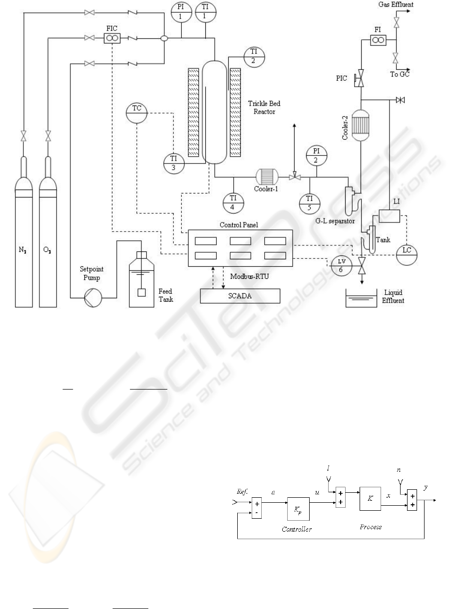
Figure 1: Wet Air Oxidation process diagram. Abbreviations: FI: Flow indicator; FIC: Flow indicator and controller; GC:
Gas Chromatography; LC: Level controller; LI: Level indicator; LV: Regulation valve; PI: Pressure indicator; PIC: Backup
pressure regulator; SCADA: System control and data acquisition; TI: Temperature indicator.
⎟
⎟
⎠
⎞
⎜
⎜
⎝
⎛
−
++=
−
=
∑
s
nn
d
n
j
sj
i
npn
T
ee
TTe
T
eKu
1
1
1
(2)
Index n refers to time instant. By tuning we shall
mean the activity of adjusting the parameters K
p
, T
i
and T
d
. Several tuning aspects may be illustrated by
static considerations. For purely proportional control
(T
d
= 0 and 1/T
i
= 0), the control law (2) reduces to
the following equation:
u
n
= K
p.
e
n
(3)
Considering the feedback loop in Figure 2, where
the controller has the proportional gain K
p
and the
process has the gain K in steady state, the output x
can be related to the reference (ref.), the load l, and
the measurement noise n by the following equation:
()
l
KK
K
nref
KK
KK
x
pp
p
+
+−
+
=
11
(4)
If n and l are zero, then K
p
should be high in
order to insure that the process output x is close to
the ref. Furthermore, if l is nonzero, a high value
will make the system less sensitive to changes in the
load l. But if n is nonzero, K
p
should be moderate
otherwise the system will be too sensitive to noise.
Obviously, the setting of K
p
is a balance between:
stability, noise sensitivity, and load regulation.
Figure 2: Closed loop system identification.
A PID controller may be tuned using the Ziegler-
Nichols frequency response method, according to the
following procedure:
DESIGN OF AN AUTOMATED FIXED BED REACTOR USED FOR A CATALYTIC WET OXIDATION PROCESS
367
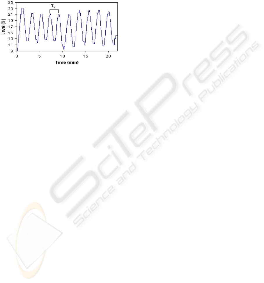
(a) Increase the proportional gain until the
system oscillates (Figure 3); that gain is the ultimate
gain K
u
.
(b) Read the time between peaks T
u
at this
setting.
(c) Approximate values for the controller
parameters are given in a table.
Figure 3: Ziegler-Nichols frequency response method.
The sample period may be related to the
derivative gain T
d
. In connection with the Ziegler-
Nichols rules, this implies that T
s
should
approximately be equal to 1 – 5 percent of the
ultimate period T
u
. Taking full advantage of this
method; we were able to adequately control the
reactor temperature and the liquid evacuation unit.
When the system reaches the steady state, the
controller allows us to maintain a constant liquid
level in the tank. Consequently, liquid flow can be
continuously evacuated at the system’s outlet.
4 HUMAN MACHINE
INTERFACE (HMI)
An operator’s graphical interface was developed
using the FIX MMI Intellution SCADA software
which combines high performance monitoring and
control with wide range of data acquisition on the
Windows NT/2000/9x operating systems. The FIX
application contains three sets of multithreaded
processes: the user process (HMI), the FIX engine
and the industrial automation device servers. These
processes interact through a client-server
relationship. The user process displays the user
interface and executes blocks of code that are
defined for control algorithms, supervisory control,
analysis and visual presentation. The event-driven
engine maintains a real time database, communicates
with device servers and performs a multitude of
tasks including engineering unit scaling, alarm
processing and historical data collection and
trending. Device servers are the applications that
communicate with Input/Output devices. The FIX
application establishes a communication with the
ISM112 intelligent sensor modules through the
deployment of a Modbus RTU server fully
compliant with the latest Modbus RTU protocol
definitions. Therefore, the ISM112 data registers can
be accessed and modified to the desired values
allowing thus the operator to have full control of the
process variables.
5 CONCLUSION
The aim of this work is to setup an oxidation process
that meets the conditions needed for the aqueous
destruction by oxygen or air of organic pollutants.
The aforementioned techniques and equipments
which in priority are based on regulation and
automation procedures, allowed us to design an
automated fixed bed reactor that fulfills the required
temperatures and pressures conditions (up to 300°C
and 25 bar) usually used for CWAO processes. The
developed monitoring interface allows the operator
to easily manage and control the process parameters.
Chemical runs allowing us to validate the system
efficacy during the oxidation of various types of
aqueous wastes, are in process of completion.
REFERENCES
Debellefontaine, H., Foussard, J.N.,Wet air oxidation for
the treatment of industrial wastes, Waste Manage., 20
(2000) 15.
Imamura, S., Fukuda, I., Ishida, S., Wet oxidation
catalyzed by ruthenium supported on cerium(IV)
oxide, Ind. Eng. Chem. Res., 27 (1988) 718.
Masende, Z.P.G., Kuster, B.F.M., Ptasinski, K.J., Janssen,
F.J.J.G., Katima, J.H.Y., and Scouten, J.C., Platinium
catalysed wet oxidation of phenol in a stirred slurry
reactor: A practical operation window, Appl. Catal. B,
41 (2003) 247.
Mishra, V.S., Mahajani,V.V., Joshi, B., Wet Air
Oxidation, Ind. Eng. Chem. Res., 34 (1995) 2.
Oliviero, L., Barbier Jr, J., Duprez, D., Guerrero-Ruiz, A.,
Bachiller-Baeza, B., Rodriguez-Ramoz, I., Catalytic
wet air oxidation of phenol and acrylic acid over Ru/C
and Ru–CeO
2
/C catalysts, Appl. Catal. B, 25 (2000)
267.
Pintar, A., Levec, J., Catalytic oxidation of organics in
aqueous solutions : I. Kinetics of phenol oxidation, J.
Catal., 135 (1992) 345.
Tan, W., Liu, J., Chen, T., and Marquez, H.J.,
Comparaison of some well-known PID formulas,
Comput. Chem. Eng., 30 (2006) 1416.
ICINCO 2007 - International Conference on Informatics in Control, Automation and Robotics
368
