
ENTANGLEMENT DETECTION OF A SWARM OF TETHERED
ROBOTS IN SEARCH AND RESCUE APPLICATIONS
T. R. Vishnu Arun Kumar and R. C. Richardson
School of Computer Science, University of Manchester, Manchester, United Kingdom
Keywords: USAR, swarm of robots, tether, entanglement detection.
Abstract: In urban search and rescue (USAR) applications, robots play a pivotal role. As USAR is time sensitive,
swarm of robots is preferred over single robot for victim search. Tethered robots are widely used in USAR
applications because tether provides robust data communication and power supply. The problem with using
tethers in a collapsed, unstructured environment is tether entanglement. Entanglement detection becomes
vital in this scenario. This paper presents a novel, low-cost approach to detect entanglement in the tether
connecting two mobile robots. The proposed approach requires neither localization nor an environment
map. Experimental results show that the proposed approach is effective in identifying tether entanglement.
1 INTRODUCTION
USAR is a time-critical process, which involves
complex and hazardous environment. Secondary
collapse, confined space, presence of fire and
poisonous gas in the environment pose serious
threats to the human and canine rescuers. Thus,
robots become inevitable in the field of search and
rescue. Mobile Robots can be used for a variety of
tasks such as localization, communication, victim
search, biomedical monitor delivery, environment
monitoring and reconnaissance. It is desirable to
deploy a swarm of robots as the survival rate of the
victims falls drastically after 72 hours.
Untethered autonomous robots depend on
wireless communication for information exchange.
When such robots are employed simultaneously in
the same area, issues such as interferences with other
systems, data security and international band
differences will arise as stated in (Fukushima et al.).
Tethered robots are used in a variety of applications
in ground, under-water and space environments
(Fukushima et al.). During recent times, tethered
robots are being employed in search and rescue
because tethers inherently provide robust data
communication and uninterrupted power delivery
(Fukushima et al.), (Hert et al., 1999). Tethers can
be used for navigating the robots through steep
slopes (Fukushima et al.) and also for pulling the
robot out when it gets stuck into debris (Perrin et
al.).
When a swarm of tethered robots is employed in
USAR environment, the tether might get entangled
with the obstacles or fellow robots. Entanglement
detection becomes an important problem that needs
to be addressed. Despite this, the merits of using
tethers make them a valid option even in search and
rescue scenario. Traditionally there are different
techniques to tackle entanglement detection. Most of
them need the robot to localize using an
environment map, which is then used to detect the
existence of tether entanglement. Navigation
planning could be done in such a way that there is no
tether entanglement (Hert et al., 1999). A method to
plan the shortest path for a tethered robot to a
destination point has been discussed in (Xavier,
1999).
In this paper, a novel, low-cost technique to
detect tether entanglement has been proposed. This
technique does not need the swarm of robots to be
localized. It does not require any environment map.
Section 2 discusses related work on localization and
map building in USAR. In Section 3, the tether
entanglement detection hardware is explained.
Section 4 throws light on experimental results and
Section 5 deals with the characterization of tether
entanglement using the experimental results. In
Section 6, a static model of tether is derived and the
experimental results are analyzed using the model.
Section 7 and 8 discuss current work and conclusion
respectively.
143
R. Vishnu Arun Kumar T. and C. Richardson R. (2007).
ENTANGLEMENT DETECTION OF A SWARM OF TETHERED ROBOTS IN SEARCH AND RESCUE APPLICATIONS.
In Proceedings of the Fourth International Conference on Informatics in Control, Automation and Robotics, pages 143-148
DOI: 10.5220/0001626001430148
Copyright
c
SciTePress
2 RELATED WORK
In USAR, communication and power supply play
crucial role. In case of autonomous robots using
wireless communication, the information exchange
is always noisy because of the thick concrete and
steel structures present in the search and rescue
environment (Perrin et al.). Also untethered robots
carry on board power supply for their operation.
This limits the life time of the entire system. So
tether based multi-robot systems are preferred over
untethered robots in search and rescue scenario. In a
tether based multi-robot system, a robot can detect
tether entanglement based on its pose in the
environment map and the pose of the fellow robots
in the same map. This technique is often referred to
as Simultaneous Localization and Map building
(SLAM) (Wijesoma et al., 2004).
One of the approaches for SLAM is to use
Inertial Measurement Unit (IMU) for localization
and Global Positioning System (GPS) for map
building. An Inertial Navigation system has errors
rising from factors like bias, scale factor
uncertainties, misalignment errors and noise
(Sukkarieh et al., Volume 19). Also in an uneven
terrain, gyrometer readings tend to be very noisy.
Fault detection and fault isolation form an integral
part of an IMU as stated in (Sukkarieh et al.,
Volume 19). In search and rescue scenario, GPS
becomes futile as discussed in (Gustafon et al.,
2005), (Cheng et al., 2004), and (Ramirez-Serrano et
al., SSRR).
Vision based approaches, which rely on
landmarks are used to localize the robot (Saeedi et
al., 2003), (Ramirez-Serrano et al., SSRR). As
search and rescue environment is complex and
unstructured, landmark based approaches are not
efficient (Cheng et al., 2004). The same reason can
be applied to (Saeedi et al., 2003) in which a vision
based approach for 3D localization and tracking has
been proposed. In this approach, distinctive scene
features extracted from the environment are used for
localization, but uncertainty in perception rising due
to different regions appearing similar is an issue to
be addressed.
The concept of Intelligent Dynamic Landmarks
is discussed in (Ramirez-Serrano et al., SSRR),
wherein some members of the robot group act as
portable landmarks for other robots to localize. In
(Gustafon et al., 2005), a swarm of robots have been
employed to achieve localization and target
identification. Line of sight approach is adopted to
localize heterogeneous teams of robots in
(Grabowski et al., 2004).
In order to detect tether entanglement, most of
the approaches need the robots to be localized and/or
an environment map. In this paper, a novel tether
entanglement detection technique has been proposed
that eliminates the need for localization and
environment map.
3 ENTANGLEMENT
DETECTION HARDWARE
The essence of this approach is that by recoiling
tethers and monitoring the force across the tether
during this process, entanglements, snags and
chafing effects on the tether can be detected. The
proposed system consists of two components (i) the
tether winding unit that pulls up tether slack (ii) a
sensor to detect horizontal forces across the tether.
The principle described here is to be applied to
swarms of interlinked tethered robots.
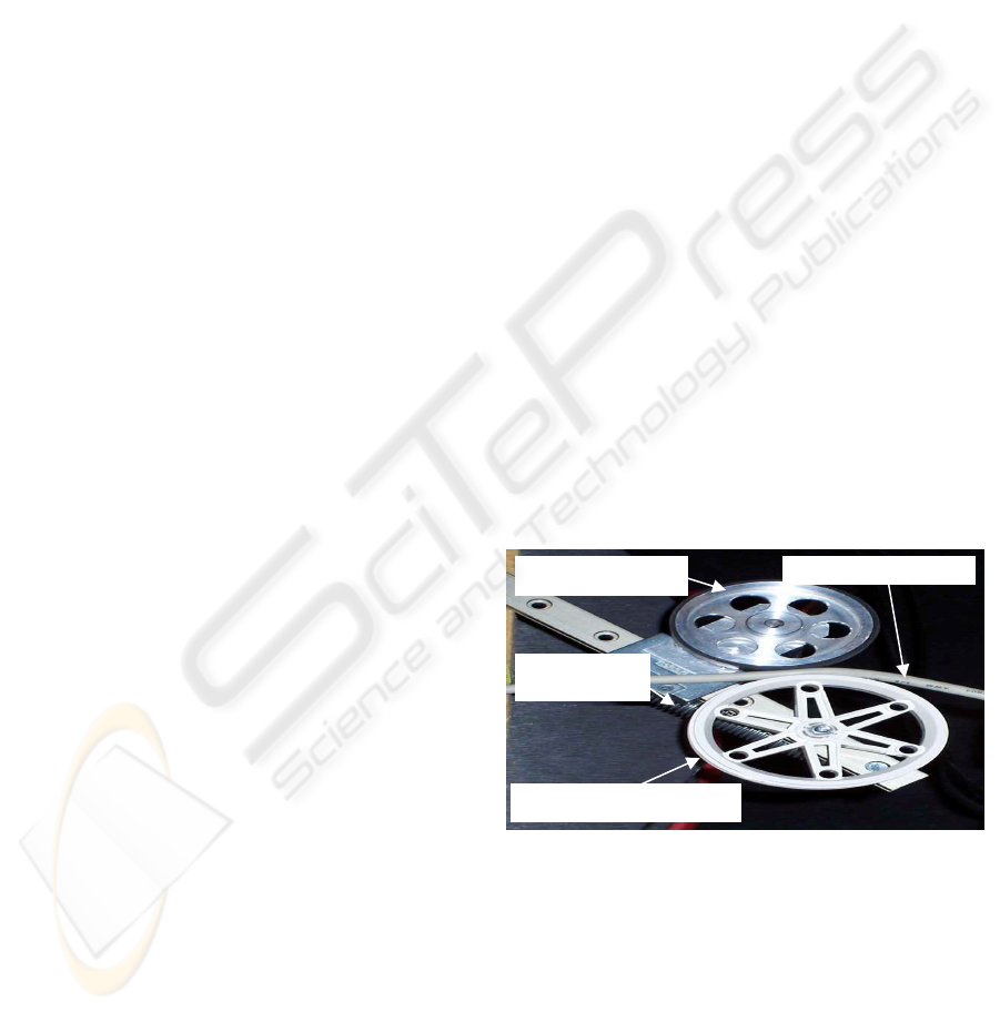
3.1 Tether Winding Unit (TWU)
Tether Winding Unit comprises of a pair of wheels
tightly coupled with a spring. One of the wheels is
driven by a 6 volt-5 Watt DC Motor. The tether
passes between a pair of wheels as shown in the
Figure-1. This unit is mounted on one of the robots
(Robot-A). There is an automatic wire coiling
system on the robot, which would hold one side of
the cable.
Figure 1: Tether Winding Unit (TWU).
3.2 Force Measurement Unit (FMU)
This unit comprises of a force sensor to measure the
force exerted on the tether. This unit is mounted on
the other robot (Robot-B). Tether entanglement
detection is carried out in the following steps:
Step-1: The tether connecting two robots is pulled
taut using the TWU.
Step-2: During that process, the horizontal force
exerted on the tether is measured using the FMU.
Drive wheel
Passive support wheel
Tension
spring
Multi-core tether
ICINCO 2007 - International Conference on Informatics in Control, Automation and Robotics
144
Step-3: Based on the pattern in which the force
exerted on the tether increases, it can be identified
whether the tether is snagged by an obstacle or not.
4 EXPERIMENTAL RESULTS
Tether Entanglement can be detected experimentally
through Snag Test, which makes use of TWU
attached to one robot and FMU attached to the other
robot. An open loop test is performed under four
different scenarios with or without obstacles. The
input voltage and the output force are recorded
during each test. Each of the four scenarios depicts
different levels of friction and different tether
dynamics involved when the tether is being pulled.
The scenarios are as follows:
Case-A is the scenario in which the tether is
freely hanging and there is no entanglement. Case-B
models the scenario in which the tether is stuck in
rubble and is subjected to friction at discrete points
along its length, as a result of which there is an
uneven movement when it is being pulled. In Case-
C, as the tether is wound around a pillar-like object,
the friction would be so high that the TWU would
not be able to hold the tether taut. Case-D depicts a
scenario in which the tether is bent by pillar-like
object and there is slow and steady movement of the
tether when it is being pulled. This is because the
friction is uniform through out the length of contact
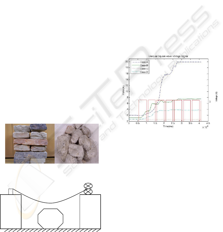
with the obstacle. Figure 2 shows a snapshot of
rubble and pillar-like objects respectively.
Figure 2: Snapshot of rubble and pillar-like objects.
Figure 3: Schematic of Experimental Setup.
The snag test is conducted using unequal square
wave pulse, which excites the system so that the
dynamic effects of the tether being pulled are tested
on different lengths of the tether at different stages
of the experiment. Also the pulsing signal would
excite the stick-slip friction. A schematic of the
experimental setup is shown in Figure-3.
The force sensor readings are plotted against
time for all the four scenarios along with the unequal
square wave input signal as in Figure-4. Initially as
the input voltage is zero, the force exerted on the
tether remains a constant. After 6000ms, the voltage
raises to +2 V. This is reflected in the graph as steep
raise in the force value. It is also observed that there
is a lag between the time of application of the
voltage pulse and the time at which the force value
starts to raise. This is because the force exerted on
one end of the tether by TWU has to reach the other
end of the tether containing the FSU.
Figure 4: Input-Output Graph.
5 CHARACTERISATION OF
TETHER ENTANGLEMENT
In Figure-4, the force value for Case-A raises steeply
whenever the voltage pulse is applied because the
tether is hanging freely. For Case-B, there is uneven
raise in force value, as the friction from the rubble
acts at discrete point throughout the length of
contact of the tether. Case-C has no effect in force
value, as the tether is completely snagged and the
friction is so high that it is not possible for the TWU
to pull the tether. For Case-D, as there is uniform
friction throughout the length of the tether, there is a
smooth transition in the force value.
The force curves are analyzed using three
different methods namely Range of force analysis,
Area under the curve analysis and Static Model
Force Sensor
T
WU
Robot - A
Robot - B
Object
(Obstacle)
Tether
ENTANGLEMENT DETECTION OF A SWARM OF TETHERED ROBOTS IN SEARCH AND RESCUE
APPLICATIONS
145
Analysis. From these analyses, an attempt has been
made to identify the type of snag from the force
sensor readings.
5.1 Range of Force Analysis
In this method, the force curve is preprocessed so
that any offset in force is eliminated. From the force
curves, it is very evident that when the tether is not
snagged by an obstacle (Case-A), the TWU holds
the tether taut and the maximum force is around 18
N. For all the scenarios where the tether is
entangled, the maximum force is around 6 N as
shown in Table-1. Thus Force Range can be used as
a parameter to model the type of snag.
5.2 Area Under Curve Analysis
If there are false spikes in the force curve due to
factors like slippage, drift, small object falling on the
tether, analysis using range of force would be
misleading. Area under curve analysis would reduce
such effects. After eliminating the offset from the
curves, the area is calculated as summation of the
product of the time interval (20ms) and
corresponding force value. The mean area of the
force curve for the three samples is calculated for all
the four different scenarios and listed in Table-1.
It could be seen that Case-A has maximum area
of around 400 square units. For Case-B and Case-D
the area is around 200 and 100 square units
respectively. Case-C has least area of less than
unity. Thus for a given input signal, based on the
area under the force curve, the type of snag can be
determined. For this analysis, time duration of the
test plays a significant role, as the area of the curve
is directly proportional to time.
Table 1: Average values of Force Range and Area under
Curve.
Case Force Range
(N)
Area under Curve
(square units)
A
18.195 400.0576
B
6.627 173.9507
C
0.124 0.1794
D
3.289 89.2996
6 TETHER MODELLING
From the experimental results it was observed that
the system is non-linear. This is evident from the
force curves in Figure-4. A non-linear model of the
system would give better insight into the behavior of
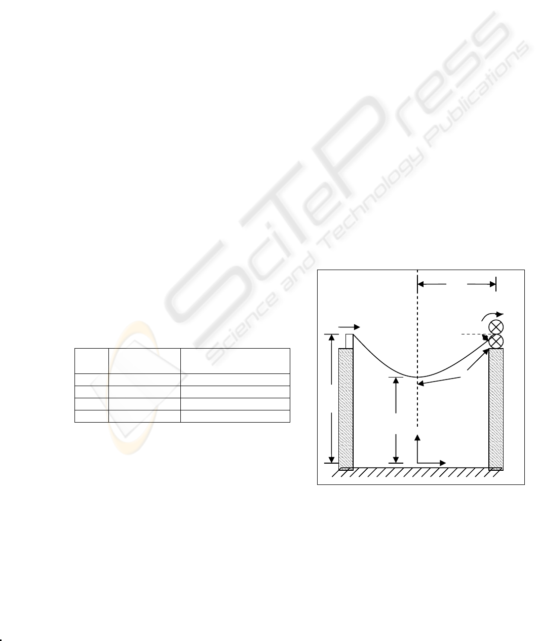
the system. A static model of the Tether
Entanglement Detection System (TEDS) is shown in
Figure-5. It comprises of two robots (Robot-A and
Robot-B) connected using a tether. Robot-A has the
tether linked with FMU. Robot-B has the tether
passing through TWU. The following are the
parameters, which influence the model.
F
pull
- Horizontal pulling force (N)
θ
sag
- Sag angle of the tether (radian)
α
wheel
- Angular Velocity of drive wheel (radian /s)
L
c
- Half of the catenary length of the tether (m)
L
h
- Half of the horizontal length of the tether (m)
a - Distance between the vertex and the axis of
the catenary curve (m)
Z
w
- Distance of the top of the catenary curve
from its axis (m)
6.1 Static Model of Freely Hanging
Tether - Derivation
A static model of the tether based robot system has
been derived. It is assumed that the dynamic effects
of the tether are negligible because the angular
velocity of the wheel α
wheel
is low. It is also assumed
that the mass is evenly distributed throughout the
length of the tether and the curve created by the
freely hanging tether is a catenary curve. A catenary
curve is the shape created by a chain-like object
fixed on both ends and hanging freely under the
force of gravity. The model can be used to determine
the horizontal pulling force (F
pull
) acting on the
tether and the sag angle (θ
sag
) of the tether (Flugge,
1962).
Figure 5: Tether Entanglement Detections System (TEDS)
Model.
F
pull
z
x
α
wheel
θ
sag
L
h
Z
w
a
L
c
Robot - B
Robot - A
ICINCO 2007 - International Conference on Informatics in Control, Automation and Robotics
146
6.1.1 Horizontal Pulling Force Derivation
The horizontal pulling force (F
pull
) is given by the
following formula:
aqF
pull
×=
(1)
where
q – weight per unit length of the tether (N/m)
In order to determine ‘a’, the following formulae are
used.
⎟
⎟
⎠
⎞
⎜
⎜
⎝
⎛
××
⎟
⎠
⎞
⎜
⎝
⎛
−= t
R
LL
wheelinic
α
2
(2)
⎟
⎠
⎞
⎜
⎝
⎛
×=
a
L
aL
h
c
sinh
(3)
where
L
ini
– Half the initial length of the tether (m)
R – Radius of the wheel (m)
Formula (2) is used to deduce the value of L
c
. This
value is used in formula (3) to find out the value of
‘a’ by creating the following non-linear equation:
⎟
⎟
⎠
⎞
⎜
⎜
⎝
⎛
⎟
⎠
⎞
⎜
⎝
⎛
×−=
a
L
aLaf
h
c
sinh)( = 0
(4)
Newton-Raphson iterative method is used to solve
the above equation. For that the derivative of f(a) is
needed.
⎟
⎟
⎠
⎞
⎜
⎜
⎝
⎛
⎟
⎠
⎞
⎜
⎝
⎛
×
⎟
⎠
⎞
⎜
⎝
⎛
+
⎟
⎠
⎞
⎜
⎝
⎛
−=
a
L
a
L
a
L
af
hhh
coshsinh)(
'
(5)
Assume the first guess
h
La =
0
,
then
⎟
⎟
⎠
⎞
⎜
⎜
⎝
⎛
−=
)(
)(
0
'
0
01
af
af
aa
,
⎟
⎟
⎠
⎞
⎜
⎜
⎝
⎛
−=
)(
)(
1
'
1
12
af
af
aa
…
This is repeated until
threshold
a
aa
k
kk
<
⎟
⎟
⎠
⎞
⎜
⎜
⎝
⎛
−
+
+
1
1
(6)
Threshold can be lower than 0.00001. Lower the
threshold higher is the accuracy of the value of ‘a’.
The value of a
k+1
is used as the value of ‘a’ in
formula (1).
6.1.2 Sag Angle Derivation
The formula for Sag angle is as follows:
⎟
⎟
⎠
⎞
⎜
⎜
⎝
⎛
=
w
sag
Z
a
acos
θ
(7)
where
⎟
⎠
⎞
⎜
⎝
⎛
×=
a
L
aZ
h
w
cosh
(8)
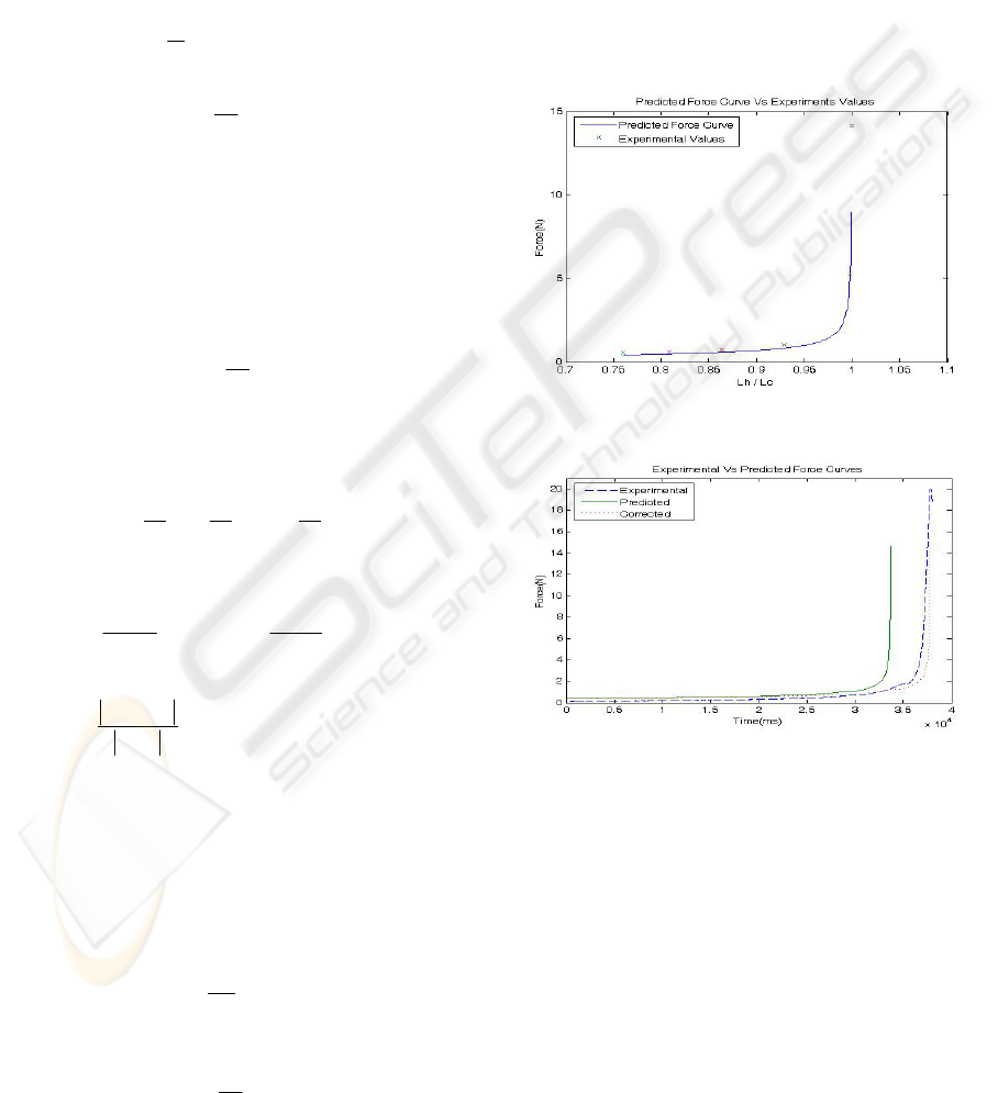
6.2 Analysis
The static model is verified experimentally by
measuring the force sensor readings for different
catenary length of the tether (L
c
) keeping the
distance between the robots (L
h
) as constant. Then a
graph is plotted with x-axis containing the ratio
between L
h
and L
c
and y-axis containing the
corresponding force readings. In the same graph the
force curve predicted using the static model for the
same value of L
h
is drawn as shown in the Figure-6.
It is observed that the actual force readings are very
close to the predicted values. This validates the static
model.
Figure 6: Predicted Force Curve Vs Experimental values.
Figure 7: Actual Vs Predicted Vs Corrected Force Curve.
Figure-7 shows the actual force readings and
those predicted using the static model for Case-A.
The predicted force curve closely follows the pattern
of the actual force curve except that it lags in time.
This is because the angular velocity of the drive
wheel will reduce when it is running under load
(tether passing through the wheels) compared to no
load condition. This is verified by simulating the
predicted force curve with 90% of the measured
angular velocity. The corrected curve matched very
closely to the experimental force curve as shown in
Figure-7. Another reason for the time lag could be
attributed to slippage of the tether. An optical
ENTANGLEMENT DETECTION OF A SWARM OF TETHERED ROBOTS IN SEARCH AND RESCUE
APPLICATIONS
147

encoder could be attached to the wheel to measure
the tether length, as it eliminates the time lag error.
From the above three analyses, it is evident that
the static model analysis is more promising than the
other two methods in terms of providing an accurate
model of freely hanging tether. Such a model can be
used to predict the force curve for freely hanging
scenario and the predicted curve can be compared
with the experimental curve. Based on the error
between the two curves, it could be identified
whether the tether is freely hanging or snagged with
obstacles. The static model can also be used to
identify different types of snags if dynamic effects
are introduced into it. One such approach could be
friction modeling.
7 CURRENT WORK
Currently friction modeling is being investigated to
understand the dynamic effects of the system. Also a
robust and low-cost 3D localization strategy for a
swarm of tethered robots is being developed. This
technique does not require an environment map for
localization. It includes a tether length measurement
unit (TLMU) and a tether orientation measurement
unit (TOMU) to localize the robot in 3D space.
TLMU comprises of an optical encoder attached to
the passive wheel of the TWU to measure the length
of the tether. TOMU consists of a joystick attached
to the end of the TWU to measure pitch and roll of
the tether.
8 CONCLUSION
In this paper a novel, low-cost and robust system,
which does not require localization or environment
map to detect tether entanglement has been
proposed. A static model has been derived for the
proposed system. Experiments have been conducted
to verify the validity of the approach. The results are
analyzed using three different methods. From the
analyses it is clear that the static model analysis is a
promising way of detecting entanglement because it
clearly identifies the scenario in which the tether is
freely hanging.
REFERENCES
Erik H. Gustafon, Christopher T. Lollini, Bradley, E.
Bishop, Carl E. Wick, “Swarm Technology for Search
and Rescue through Multi-Sensor Multi-Viewpoint
Target Identification”, Proceedings of the Thirty-
Seventh South-eastern Symposium on System Theory
(SSST 2005), Page(s):352 – 356
Edwardo F. Fukushima, Noriyuki Kitamara, Shigeo
Hirose, “A New Flexible Component for Field
Robotic System”, Proceedings of the IEEE
International Conference on Robotics and Automation,
San Francisco, CA, Page(s): 2583 – 2588
Doughlas P. Perrin, Albert Kwon, Robert D. Howe, “A
Novel Actuated Tether Design for Rescue Robots
using Hydraulic Transients”, Proceedings of the IEEE
International Conference on Robotics & Automation,
Page(s): 3482-3487
Patrick G.Xavier,“Shortest path planning for a tethered
robot or an anchored Cable”, Proceedings of the IEEE
International Conference on Robotics and Automation
(ICRA 1999), Volume 2, Page(s): 1011- 1017
Susan Hert, Vladimir Lumelsky, “Motion Planning in R
3
for Multiple Tethered Robots”, IEEE Transactions on
Robotics and Automation, Volume 15, Issue 4, August
1999, Page(s): 623 – 639
Chee Kong Cheng; Leng, G., “Cooperative search
algorithm for distributed autonomous robots”,
Proceedings of IEEE/RSJ International Conference on
Intelligent Robots and Systems, (IROS 2004), Volume
1, Page(s):394 - 399
P. Saeedi, D. G. Lowe, P.D.Lawrence, “3D Localization
and tracking in unknown environments”, Proceedings
of the IEEE International Conference on Robotics and
Automation (ICRA 2003), Volume 1, Page(s):1297 –1303
Salah Sukkarieh, Peter Gibbens, Ben Grocholsky, Keith
Willis, Hugh F. Durrant-Whyte, “A Low-Cost
Redundant Inertial Measurement Unit for Unmanned
Air Vehicles”, International Journal of Robotics
Research, Volume 19, No. 11, Page(s): 1089-1103
Alejandro Ramirez-Serrano, Giovanni C. Pettinaro,
“Navigation of Unmanned Vehicles Using a Swarm of
Intelligent Dynamic Landmarks”, Proceedings of
IEEE International Workshop on Safety, Security and
Rescue Robotics (SSRR), Page(s): 60 – 65
Robert Grabowski, Pradeep Khosla, Howie Choset,
“Development and Deployment of a Line of Sight
Virtual Sensor for Heterogeneous Teams”,
Proceedings of IEEE International Conference on
Robotics and Automation (ICRA 2004), Volume
1, Page(s):3024 – 3029
W.S. Wijesoma, L. D. L. Perera, M. D. Adams,
“Navigation in Complex Unstructured Environments”,
Proceedings of 8
th
International Conference on
Control, Automation, Robotics and Vision (ICRA
2004), Volume 1, Page(s): 167 – 172
W. Flugge, “Handbook of Engineering Mechanics”, First
Edition 1962, McGraw-Hill Book Company, Page(s):
4.7, 21.15
ICINCO 2007 - International Conference on Informatics in Control, Automation and Robotics
148
